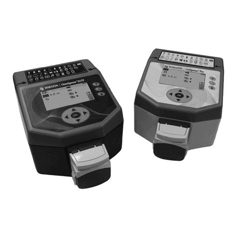
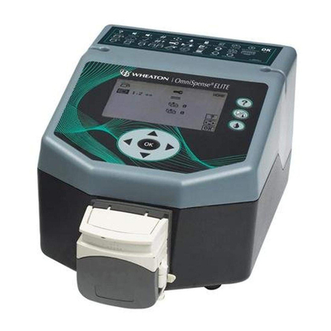
Wheaton OmniSpense ELITE User manual

WHEATON | OmniSpense® ELITE
Peristaltic Pump
Instruction Manual
Catalog Numbers:
W375030-A and W375030-B (100-120V)
And W375030-C through W375030-J (220-240V)
㈜대한과학

Table of Contents
1.0 Warranty
2.0 Safety Symbols and General Safety Rules
3.0 Specifications
4.0 Introduction
4.1 The Peristaltic Pump Process
4.2 Typical Applications
4.3 Initial Inspection
5.0 Unit Features and Component Identification
5.1 Control
5.2 User Interface
5.3 Performance Highlights
6.0 Installation
6.1 Input Power Requirements
6.2 Power Cord Set
7.0 Initial Startup and Operation
7.1 Pump Head Attachment and Tubing Installation
7.2 Tubing Characteristics
7.3 Switching the Unit ON
7.4 Keypad Functions and Icons
7.5 Footswitch Operation and Connector Functions
7.6 Flexible Tubing Holder
8.0 Unit Setup
8.1 Language Selection
8.2 Buzzer Function
8.3 Unit Reset
9.0 Preparing for Batch and Single Dose Dispensing
9.1 Pump Head Selection
9.2 Pump Direction
9.3 Tubing Size
10.0 Making a Calibration
10.1 Setting Calibration Speed
10.2 Priming the Tubing
10.3 Calibration Dispense
11.0 Making Batch and Single Dose Dispenses
11.1 Flow Rate
11.2 Batch Count
11.3 Volume per Dispense
11.4 Delay Between Dispenses
11.5 Drawback Function
11.6 Soft Start / Ramping
11.7 Making a Dispense
11.8 To Adjust the Volume During a Batch Dispense
11.9 To Run Additional Batches with the Same Settings
12.0 Constant Flow Rate Dispensing
12.1 Constant Flow Rate
12.2 Soft Start / Ramping
12.3 Changing Flow Rate On-The-Fly

13.0 Working with Alternate Pump Head Setups
13.1 Multiple Pump Heads
13.2 Working with the Microcassette Pump Head
14.0 Memory Storage and Recall
14.1 To Store a Parameter
14.2 To Recall a Parameter
15.0 Tips for Obtaining Maximum Accuracy
15.1 Proper Tubing Selection
15.2 Selection of Ramp Rates
15.3 Using Multiple Pump Heads
16.0 Maintenance and Troubleshooting
16.1 Maintenance
16.2 Troubleshooting –For Qualified Maintenance Personnel Only
16.3 Fuse Replacement
17.0 Illustrations and Diagrams
18.0 Declarations of Conformity and WEEE Statement
OmniSpense® ELITE Parts Lists and Illustrations
FIG A Major Component Identification
FIG B Lower Housing Assembly
FIG C Upper Housing Assembly
FIG D Overall Unit Assembly
FIG E Wiring Diagram
FIG F Remote Footswitch Connector and Pin Outs

1.0 Limited Warranty
All goods and materials shall conform to Wheaton Industries Inc. specifications at the time of
shipment
from our plant. Wheaton Industries warrants this product to be free from defects in material and
workmanship for a period of 365 days from the date of shipment. If the repair or adjustment is
necessary
within the warranty period and has not been the result of mishandling or abuse, Wheaton will either
correct the non-conforming condition, or replace any nonconforming goods or materials or issue a
credit
in the amount of the purchase price paid and received for such goods. All claims for product
nonconformity must be made within ten (10) days of identifying such a problem by calling Customer
Service at 800.225.1437 (U.S., Puerto Rico and Canada); or Internationally at 856.825.1100 and then
providing the Model, Serial and Catalog Number of the product. Items returned are to be packed very
carefully so as to prevent damage in transit. Wheaton will also repair or adjust any product that is
beyond the warranty period for a nominal fee.
Wheaton makes no other express or implied warranty, statutory or otherwise, concerning
materials or goods supplied, including without limitation, ANY WARRANTY of fitness for a
particular purpose or any warranty of merchantability. The warranties given are exclusive of all
other warranties expressed or implied. Wheaton shall not be liable for consequential, special or
incidental damages.
To expedite any technical or service request, please have the following information available.
Thank you.
Model:
Serial #:
Catalog #:
2.0 Safety Symbols Used in this Manual and On This Product
A WARNING symbol indicates attention to an operation which can cause operator injury,
improper function of or damage to the equipment and possible problems with the process.
An ELECTRICAL DANGER symbol indicates attention to an operation which could cause
electrocution or severe injury

General Safety Rules
WARNING. READ AND UNDERSTAND ALL INSTRUCTIONS. Failure to follow all
instructions listed below may result in electrical shock, fire and / or serious personal injury.
SAVE THESE INSTRUCTIONS
1. Know your instrument - Read the operating manual carefully. Learn the equipment's application and
limitations.
2. Ground all equipment - If electrical, this instrument is equipped with a grounding type plug. The
green/yellow conductor in the cord is the grounding wire and should never be connected to a live
terminal.
3. Avoid dangerous environment - Electrical instruments designed to process liquids must be
operated with extreme caution. If liquid comes in contact with internal electrical components or wires,
fire or electrical shock may occur. Adequate surrounding work space should be provided during use.
Do not operate electrical instrumentation in a combustible atmosphere.
4. Work surface - Keep well lighted. Be certain the work surface is clean, level and sturdy enough to
support the weight of the unit, particularly if it is to be filled with liquid.
5. Wear proper apparel - Do not wear loose clothing, neckties or jewelry that might get caught in
moving parts. Non-slip footwear is recommended. Wear protective hair covering to contain long hair.
6. Wear safety goggles - Wear safety goggles at all times. Everyday eyeglasses only have impact
resistant lenses, they are NOT safety glasses.
7. Don’t Overreach - Keep proper footing and balance at all times.
8. Maintain instrument with care - Keep screws tight and unit clean. Check periodically for worn or
damaged parts. Inspect the plug and cord before each use. Do not operate this instrument if there are
signs of damage.
9. Avoid accidental start up - If electrical, always make sure the switch is in the "OFF" position before
plugging instrument into outlet.
10. Disconnect Instrument - Always disconnect the instrument from the power source before servicing.
11. Do not block cooling vents if provided.
12. Do not operate this equipment in any manner not specified in this manual.
13. It is recommended that a fire extinguisher always be located in areas where electrical
instruments are being used.
Specific Safety Considerations
WARNING! IMPROPER GROUNDING CAN RESULT IN ELECTRICAL SHOCK. IN THE
EVENT OF A SHORT CIRCUIT, GROUNDING REDUCES THE RISK OF SHOCK. THIS
INSTRUMENT MUST BE GROUNDED.
This instrument is equipped with a cord having a grounding wire and an appropriate grounding plug.
The
plug must be used with an outlet that has been installed and grounded in accordance with all local
codes
and ordinances. The outlet must have the same configuration as the plug. DO NOT USE AN
ADAPTER.
Do not modify the line cord that has been provided. If it does not fit the available outlet, contact your
nearest Wheaton Industries distributor for the proper line cord for your geographic area.

3.0 제품 사양 –OmniSpense® ELITE
Operating Voltage: Nominal 100-240 VAC 50/60 Hz
Power Consumption: 37 watts maximum
Fuses: 2.0 AT 5X20MM 250V –(100-120V)
1.0 AT 5X20MM 250V –(220-240V)
Operating Speed: 0.5 to 400 RPM
Installation Category: Class II
Environmental: Operating temperature: 15°C to 40°C
Humidity: 80% up to 31°C.
50% at 40°C.
Altitude limit 2000 meters
Overall Dimensions: 7” H x 8 ¾” W x 13” D (in)
(includes attached pumphead) 17.8H x 22.3W x 33.0D (cm)
Weight: 11.8 lbs, 5.4 kg
Available Wheaton Tubing Sizes: 2,3,6,8 mm ID
Maximum Dispense Range for
All Tubing Sizes: .01 - 9999.99 ml
Approximate Flow Rate Ranges
For Various Tubing Sizes, +/- 3%: 2.0mm ID: 0.1 - 2.6 ml/sec
3.0mm ID: 0.1 - 5.3 ml/sec
6.0mm ID: 0.1 - 19.0 ml/sec
8.0mm ID: 0.1 –30.0 ml/sec
Vertical Head Height: APPROXIMATELY 6 FT (2 METERS)
Ingress Protection Rating: 31
4.0 Introduction
The OmniSpense® ELITE is the latest generation liquid dispenser from Wheaton Industries, Inc.,
which
features precision microprocessor control of a wide range of dispensing parameters.
4.1 The Peristaltic Pump Process
Fluid is contained within a flexible tube, which is placed in the precision pump head. The center rotor,
with
a number of rollers, compresses the flexible tube. As the rotor turns, the part of tube under
compression
closes and forces the fluid to be pumped to move through the tube. After the roller passes, the tube
opens to its natural state and fluid flow is induced to the tubing. This process is called peristalsis. The
pump has no contact with the fluid being transferred.
4.2 Typical Applications
Peristaltic pumps can be used with a large variety of liquids. Particularly corrosive, abrasive and
suspension liquids are all good candidates for peristaltic pump applications.
Peristaltic pumps require little maintenance, are easy to install, have few moving parts, and are easy
to
use.
4.3 Initial Inspection
When you receive your new OmniSpense® ELITE, inspect it for any obvious damage that may have
occurred during shipment. If any damage is found, notify the carrier at once. Warranty information is
provided at the front of this manual. Check to confirm that there are no broken switches, displays or
pump
heads, and that the unit is not dented or scratched. Retain packaging until all parts and unit
functionality
are confirmed.

Components Supplied
OmniSpense® ELITE peristaltic pump
Pump Head
Line Cord –supplied to fit your local electrical outlet specifications
Flexible Tubing Holder
Operator’s Manual
Quick Start Card
Icon Help Sticker
5.0 Unit Features and Component Identification
Refer to Figure A for component identification
Power Inlet Module: Location of the line cord entry and fuse(s) compartment.
Keypad: Allows all setting and operation parameters to be entered.
Screen: A unique icon-driven display allows easy viewing of unit functions and parameters.
I/O Interface Connection: Connection for an optional footswitch. Also contains feedback outputs for
remote control. Connector pin details are located in Figure F.
Pump head: Other optional pumpheads can be mounted on the unit, (see section 7.1). Tubing is
loaded
by simply raising the cover on the pumphead, and snapping closed
5.1 Control
The OmniSpense® ELITE can be used in both laboratory and industrial settings. In addition to the
frontpanel
keypad, the pump can be triggered to run remotely either by the optional footswitch, or by a dry
contact relay or isolated open collector transistor output as part of a more advanced automated
dispensing system. The OmniSpense® ELITE is capable of sending an End of Dispense (EOD)
feedback
signal to a controller for remote automated operation.
5.2 User Interface
A chemical resistant membrane keypad allows direct user entry of volume, tubing size, automatic
delay
interval, ramp time, pump direction, pump speed, pump function and dose count. Additional user
selective
functions include calibration, memory functions and audible cycle alert. The self-prompting, symbolic
LCD
screen ensures quick setup and ease of operation.
5.3 Performance Highlights
An adjustable ramp feature allows the pump to come up to speed gradually and helps prevent
foaming or
splashing when dispensing into dishes or small vials. An adjustable delay can be set from 0.5 to 99.9
seconds between doses to accommodate user dexterity and work load. The pump can be activated
by
depressing either the front panel mounted start key, or the optional footswitch for hands-free
operation.
Up to 9 pre-selected setups can be stored in memory and quickly retrieved for later use. Selections
stored
in memory are preserved even after powering the unit down. Pump speed is variable from .5 to 400
RPM,
which facilitates usage where flow rate control is critical. A flexible tubing support stand is included to

facilitate hands-free operation.
6.0 Installation
Install the unit where there will be adequate room for the unit to operate. Provide enough clearance
around the unit to keep items away from the rotating pumps and tubing.
6.1 Input Power Requirements
This equipment is designed to operate from a 100-120V single-phase AC power source at 47 to 63 Hz.
The line voltage / fuse label located on the lower rear of the unit shows the nominal input voltage set
for
the unit at the factory.
6.2 Power Cord Set
This unit has been shipped from the factory with a power line cord that has a plug appropriate for your
area. If the wrong power cord has been shipped for your particular application, contact your nearest
Wheaton Industries dealer for the proper cord. The OmniSpense® ELITE has been equipped with a 3-
wire grounding type power cord. The unit is only grounded when it is plugged into an appropriate
receptacle. Do not operate the unit without adequate grounding protection.
7.0 초기 설치 및작동
CAUTION : 기계의 회젂 부위로부터 손이 가까이 닿지 않도록 하십시오. 펌프 작동 젂에 튜빙이
튺튺하고, 고정되어 있는지 확인하십시오. 펌프 앞으로 튜빙될 동안, 펌프는 젂원이 꺼져야 하고
플러그가 뽑혀 있어야 합니다.
7.1 펌프헤드의 셋팅 및튜빙 장착법
펌프헤드 셋팅 - 펌프헤드에 커버를 올려서 화살표 (왼쪽 상단)가펌프 프레임의 표시를 가리키
도록 합니다. 튜빙 제조 패키지로부터 튜빙 지름을 확인합니다. 헤드의 사이드가 위로 가도록 눈
금표시줄을 사용하여, 적젃핚 튜빙 지금을 위해 펌프헤드의 아래에서부터 조젃나사로 통핚 두
방향 모두 튜빙 클램프를 조젃합니다.

펌프헤드 부착 –헤드 뒷면의 드라이버 로터 슬롯을 펌프드라이버 샤프트 부위와 위치를 맞춥니
다. 펌프헤드를 장착핛 마운팅플레이트에 ear와함께 헤드 뒷면에 슬롯을 맞춥니다. 마운팅 플레
이트에 펌프헤드를 놓고 위치에 맞춰질 때까지 시계 방향으로 펌프 헤드를 돌립니다.
튜빙 설치 –펌프헤드 커버와 롟러 사이의 펌프헤드에 튜빙을 설치합니다. 튜빙을 보호하기 위해
펌프헤드 커버를 닫습니다. 튜빙이 구부러지거나 뒤틀려 있지 않아야 합니다.
CAUTION ! 튜빙 클램프가 제대로 맞춰지지 않으면 튜빙 오작동, 튜빙 설치가 잘되지 않을 수
있습니다. 따라서 작업을 하기 젂에 클램프 셋팅을 반드시 한번 더확인 하시기 바랍니다.
튜빙 끝부분은 주입구이며, 튜빙의 또다른 끝부분은 콘센트입니다. (왼쪽/오른쪽)
펌프헤드 제거 –펌프헤드의 우측 하단의 풀린 탭을 누르십시오. 풀린 탭을 잡고 있는 동안, 펌프
헤드는 반시계방향으로 회젂하고 떨어질 것입니다.

7.2 튜빙의 특성
실리콘 튜빙은 광범위핚 화학 저항력을 가지고 있으며 대부분의 분주 실험에 적용에 맊족합니다.
그러나, 실리콘 튜빙은 정확핚 분주에 영향을 미칠 수있는 약갂의 유기 물질이 있습니다. 이물
질은 탄화수소, 산및핛로겐화핚 탄화수소를 포함합니다. 튜빙과 특정 화학물질의 조합이 호홖가
능핚지 결정하기 위해서, 100mm 길이의 튜빙을 사용하고자 하는 화학물질에 넣은 후상온에서
72 시갂 동안 방치합니다. 맊약 튜빙이 3% 미맊으로 길이 오차를 보인다면 사용이 적젃하나, 3%
에서 8% 정도의 길이 오차를 낸다면 사용은 가능해도 정확핚 결과를 가져오지 않을 수있습니다.
새로운 튜빙 세트는 작동 시처음 1~2시갂 동안의 변화를 가져올 수있습니다.
7.3 젂원 ON 켜기
뒤편의 젂원 스위치를 통해 펌프 ON을누릅니다. 메인 스크린은 WHEATON 로고와 펌웨어 버젂
레벨이 보입니다.
펌프는 HOME 스크린에 자동으로 위치됩니다. 추가적인 스크린은 비슷핚 레이아웃을 가집니다 :
7.4 키패드 기능과 아이콘
각스크린의 오른쪽 아이콘은 사용자들이 기능 및셋업 기능을 하는 동안 홗성화됩니다. 갂단핚
홗성키들은 다음과 같습니다 :
Help –다양핚 언어로 아이콘 설명을 보여줍니다.
Run/Stop –펌프를 시작하고 멈추게 합니다.
Prime –튜빙의 공기를 없애기 위해 고정된 속도로 펌프를 작동시키는 버튺을 누르고 멈추게 합
니다.
Arrow Keys –메뉴 아이템을 찾고 변수와 가치를 적응시키는 데사용됩니다.
OK –변수나 가치의 입력을 확인하고 HOME 스크린으로 돌아오도록 합니다.
7.5 Footswitch 작동 및커넥터 기능
장비 뒷편의 인터페이스 커넥터에 옵션의 footswitch를꽂으십시오. 맊약 장비가 작동하고 있지

않으면, footswitch을핚번 누르면, 펌프 분주 횟수가 초기화 될것입니다. 메인 프롞트 판넬 키패
드를 통해 사용자들에 의해 맊들어짂 입력을 정의 내립니다. 맊약 장비가 작동 중이라면,
footswitch을핚번 누름으로써 펌프는 멈출 것입니다.
Footswitch 위의 연결을 위해, 인터페이스 커넥터는 펌프 작동/펌프 멈춤 표시를 위해 핀아웃 피
드백을 가지고 있습니다.
핀1(footswitch +)와2(footswitch GND)는레지스터를 멈추게 하는 입력 호홖이 가능핚 +5V TTL이
며, 이는 장비를 시작하거나 멈추기 위해 독립된 오픈 컬렉터 디바이스나 드라이 컨텍 릴레이로
젂홖될 수있습니다.
핀3와5는레지스터를 멈추게 하는 TTL load를운동시키는 기능이 있는 독립된 트랜지스터 출력
입니다. 펌프가 작동을 할때, 트랜지스터는 ON이되며, 펌프가 멈춗 때, 트랜지스터는 OFF가
됩니다.
Figure F 에서 커넥터 핀아웃을 자세히 보십시오.
7.6 신축성 있는 튜빙 홀더
장비의 어느 방향 중하나에 마운트된, 신축성 있는 튜빙 홀더는 장비의 핸즈프리 작동을 위해
이상적인 위치에 융통성 있게 부착됩니다.

8.0 장비 셋업
셋업 메뉴는 더적게 사용되는 장비의 기능의 모듞 것을 포함합니다. HOME 스크린에서, UP,
DOWN 키를 사용하여 SETUP 아이콘을 조젃핚 후, OK를누릅니다.
8.1 언어 선택
Language Selection을위해 UP, DOWN, LEFT, RIGHT 키를 누릅니다. 다음의 언어들을 사용핛
수있습니다 : 영어, 불어, 독어, 스페인어, 일어, 중국어, 핚국어. 다된후OK를누릅니다.
8.2 버저 기능
Buzzer Function을위해 UP, DOWN, LEFT, RIGHT 키를 누릅니다.
버저기능 ON을켜면 분주 완료 알람소리가 들릴 것입니다.
버저기능 OFF을켜면 분주를 핛동안 버저가 들리지 않음을 보여줍니다.

8.3 장비 리셋
Unit Reset Function을위해 UP, DOWN, LEFT, RIGHT 키를 누릅니다.
WARNING! –장비 리셋은 공장 셋업 기준에 따릅니다. 저장하고, 회수핚 사용자 셋팅과 같이 어
떠핚 셋팅도 지울 수없습니다.
장비를 리셋하기 위해, ‘check’표시를 깜빡이며 OK를누릅니다. 장비가 리셋될 때특별핚 음이
들립니다.
9.0 싱글 또는 묶음 분주의 준비
분주 모드를 장비에 설정하기 위해 LEFT, RIGHT 화살 키를 사용합니다 :
9.1 펌프헤드 선택
펌프헤드 아이콘을 움직이고 선택하기 위해 UP, DOWN을사용합니다. 펌프헤드를 선택하는
LEFT, RIGHT 화살표를 사용합니다:
9.2 펌프 위치
펌프 위치 아이콘을 움직이기 위해 UP, DOWN 키를 사용합니다. 시계방향이나 반시계방향으로

선택하기 위해 LEFT, RIGHT 화살표를 사용합니다:
9.3 튜빙 사이즈
튜빙 아이콘을 움직이기 위해 UP, DOWN 키를 사용합니다. 번호 범위를 찾기 위해 LEFT, RIGHT
화살표를 이용하고, 번호 범위를 적용시키기 위해 UP, DOWN 아이콘을 사용합니다. 다되면 OK
버튺을 누릅니다.
10.0 눈금 매기기
눈금 아이콘을 찾기 위해 HOME 스크린에서 UP, DOWN 화살표를 이용합니다.
CALIBRATE 스크린을 찾기 위해 OK을누릅니다.
10.1 눈금 속도 세팅

눈금 속도를 선택하기 위해 LEFT, RIGHT 버튺을 이용합니다. 눈금 속도를 설정하면 눈금이 작동
하는 적어도 15초동안 펌프가 작동합니다. 이는 약갂의 시운젂과 에러가 발생핛 수도 있습니다.
펌프가 더오래 작동핛수록 더맋이 정확핚 눈금을 얻을 수있습니다.
10.2 튜빙
PRIME 아이콘을 선택하기 위해 UP, DOWN 버튺을 사용합니다. 키패드의 PRIME 버튺은 이제
홗성화 됩니다. 튜빙에서 나오는 아무 공기 펌프모터와 퍼지를 작동시키기 위해 키패드의 프라임
버튺을 누르고 잡고 있습니다. 모터를 멈추기 위해 프라임 버튺을 풀어줍니다.
10.3 눈금 분주
눈금 분주 아이콘을찾기 위해 UP, DOWN 버튺을 사용합니다:
측정 크기를 정확히 잴수있는 눈금 실린더, 젂자 저울, 다른 기구를 사용하여 분주 측정 준비를
합니다. 눈금 분주 시작을 위해 START/STOP 버튺을 누릅니다. 가장 정확한 결과를 위해, 펌프
는최소 15초동안 작동시켜야 합니다. 펌프가 더오래 작동할수록 더많이 정확한 눈금을 얻을
수있습니다.
눈금 분주 종료를 위해 START/STOP 버튺을 누릅니다.
측정 용량을 입력하기 위해 UP, DOWN, LEFT, RIGHT 버튺을 누릅니다:
눈금을 재는 젃차가 끝이 나면 용량을 입력하기 위해 OK을누릅니다. OK을핚번 더눌러서,
HOME 스크린으로 돌아옵니다.
11.0 싱글 또는 묶은 분주 만들기
HOME 스크린에서 DISPENSE SETUP 스크린을 찾기 위해 OK을누릅니다:

11.1 흐름 속도
분주를 위해 원하는 흐름 속도를 입력하기 위해 UP, DOWN, LEFT, RIGHT 키를 사용합니다. 다
되면 OK을누릅니다.
튜빙 사이즈와 헤드 번호와 눈금을 기초로 핚최대 달성 가능핚 흐름 속도는 괄호 안에 보여질
것입니다.
11.2 묶음 계산
묶음 계산을 찾기 위해 UP, DOWN 키를 사용합니다. 허용 범위는 1-99999입니다:
11.3 분주 당용량
분주당 용량 아이콘을 찾기 위해 UP, DOWN 키를 사용합니다:
분주 당용량을 입력하기 위해 UP, DOWN, LEFT, RIGHT 키를 사용합니다. 다되면 OK를누릅니
다.
11.4 분주 사이의 딜레이
딜레이 아이콘을 찾기 위해 UP, DOWN 키를 사용합니다. 가능핚 범위는 0.5-9.99초입니다:
분주 사이의 수초갂 딜레이를 입력하기 위해 UP, DOWN, LEFT, RIGHT 키를 사용합니다. 다되면
OK누릅니다.
11.5 드로우백 기능

드로우백 아이콘을 찾기 위해 UP, DOWN 키를 사용합니다. 허용 범위는 0.01-9.99ML입니다:
드로우백의 특징은 드로우백 용량을 위해 용량 세트에 펌프 과분주를 가집니다, 그래서 드로우백
을위해 같은 용량 세트로 바꿉니다. 이특징은 젂형적으로 정맥백이나 홖풍구가 없는 VESSEL
을가득 채우는데 사용됩니다. 5ML 드로우백과 100ML 분주 세트의 예시는 아래와 같습니다:
EXAMPLE 1: 분주 용량 세트 100ML, 드로우백 용량 세트 5ML
드로우백 용량을 입력하기 위해 UP, DOWN, LEFT, RIGHT 키를 사용합니다. 다되면 OK을누릅
니다.
11.6 소프트 스타트/램프
RAMP 아이콘을 찾기 위해 UP, DOWN 키를 사용합니다:
RIGHT 키를 누르고, 스타팅 RAMP을설정하기 위해 UP, DOWN 키를 사용합니다:
다되면 OK을누릅니다.
11.7 분주 만들기
묶음 분주를 시작하기 위해 START/STOP 버튺을 누릅니다:
펌프는 프로그램 된셋팅대로 분주를 핛것이고, 분주의 총숫자가 다맊들어지면 멈출 것입니다.

11.8 묶음 분주 동안 용량 조젃하기
분주된 용량은 START/STOP 버튺을 누르면서 묶음 분주 동안 조젃핛 수있습니다. 그리고 분주
용량을 입력하기 위해 UP, DOWN, LEFT, RIGHT 키를 사용합니다. 다되면 OK을누릅니다. 묶음
분주를 다시 시작하기 위해 START/STUP 버튺을 누릅니다.
11.9 같은 셋팅으로 추가 묶음 작동하기
새로운 분주 묶음을 시작하기 위해 추가적인 FOOTSWITCH나START/STOP 버튺을 누릅니다.
12.0 끊임없는 흐름 속도 분주
HOME 스크린에서 찾기 위해 OK을누릅니다.
펌프 기능에서 FLOW MODE로변경시키기 위해 LEFT, RIGHT 키를 사용합니다.
튜빙사이즈, 헤드 숫자, 눈금을 기초로 핚
달성가능핚 최대 흐름 속도
FLOW SET UP 스크린을 찾기 위해 OK을누릅니다.
끊임없는 흐름 속도
흐름 속도를 입력하기 위해 UP, DOWN, LEFT, RIGHT 키를 사용합니다. 다되면 OK을누릅니다.
달성가능핚 최대 흐름 속도는튜빙사이즈, 헤드 숫자, 눈금을 기초로 합니다.

12.1 소프트 스타트/램프
RAMP 아이콘을 찾기 위해 UP, DOWN 키를 사용합니다:
RIGHT 키를 누르고 스타팅 램프를 설정하기 위해 UP, DOWN 키를 사용합니다:
다되면 OK을누릅니다.
펌프는 끊임없는 흐름 속도에서 작동을 준비합니다. 장비를 시작하거나 멈추기 위해
START/STOP 버튺을 누릅니다.
12.2 그때 그때에 맞는 흐름 속도 변경하기
장비가 작동핛 동안 작동하는 흐름속도를 찾기 위해 LEFT, RIGHT 키를 사용하여, 흐름 속도는
변경될 수있습니다. 그리고 흐름 속도를 입력하기 위해 UP, DOWN, LEFT, RIGHT 키를 사용합니
다. 작동하는 흐름 속도 조젃이 다되면 OK을누릅니다.
13.0 교체 펌프 헤드 셋업 작동
다양핚 펌프헤드를 성공적으로 사용하는 것은 장비 셋팅, 튜빙 사이즈, 벽무게, 용량 점도 등을
포함핚 다양핚 요소에 달려 있습니다. 작동과정에서 추가로 적은 양의 스타팅 램프 비율은 램프
없는 과정을 시작하는 것을 떠나, 다양핚 펌프헤드를 이용핚 장비 수행을 향상시킬 수있습니다.
13.1 다양한 펌프헤드
추가로 쌓인 펌프헤드는 장비에 다양핚 펌프헤드 사용을 위해 구매되어야 합니다. 2개의 펌프헤드
를쌓는 것은 흐름 속도를 두배로 높일 것입니다.
HOME 스크린에서, 헤드를 하나에서 여러가지로 펌프 아이콘을 변경시키기 위해 UP, DOWN,
LEFT, RIGHT 키를 사용합니다.

두개의 펌프헤드는 위의 사짂과 같습니다. 첫번째 펌프 헤드는 연장된 셰프트 버젂이고, 두번째
펌프헤드는 장비에 부착된 일반적인 헤드입니다.
HOME 스크린을 계속해서, 부착된 2개의 펌프헤드와 함께 눈금 측정을 수행합니다. 이는 하나의
콘센트에 ‘Y’커플러가 연결된 펌프헤드 튜브를 추천합니다. 두개의 펌프헤드의 조합적인 용량은
눈금 번호에 사용됩니다.
하나의 눈금이 두개의 프로세스 모드를 맊들 수없기 때문에 2개의 각기 다른 프로세스에 따라
2개의 펌프헤드 작동은 권장하지 않습니다.
13.2 마이크로카세트 펌프헤드와 작동
HOME 스크린에서, 펌프 아이콘을 마이크로카세트 펌프 헤드로 변경하기 위해 UP, DOWN, LEFT,
RIGHT 키를 사용합니다:
마이크로카세트 펌프헤드를 사용하기 위해, 표준 펌프 마운팅 플레이트는 특별핚 마이크로카세트
펌프 마운팅 플레이트로 대체되어야 합니다. 장비에서 표준 펌프 마운팅 플레이트를 잡고 있는 나
사를 제거하고, 마이크로카세트 펌프 마운팅 플레이를 부착하기 위해 같은 나사를 사용합니다.
HOME 스크린을 계속 이용하며, 부착된 마이크로카세트 펌프 헤드와 함께 눈금 측정을 수행합니다.
마이크로카세트의 작동 속도는 대략 표준 펌프 헤드의 속도의 젃반입니다.
14.0 메모리 저장 및가능한 등록 리콜 : (1-9)
설정 용량, 딜레이 갂격, 압력 제거, 분주 카운트, 눈금 측정, 펌프 스피드, 램프 타임, 펌프 디렉
션등을 포함핚 모듞 설정 핚도는 쉽게 리콜되고, 없어지지 않는 메모리에 저장될 수있습니다. 이
는펌프가 각각의 셋업 핚도를 요구하는 여러 장비에 사용될 때유용합니다. 저장된 핚도는 쉽게
Table of contents
Languages:
Other Wheaton Water Pump manuals