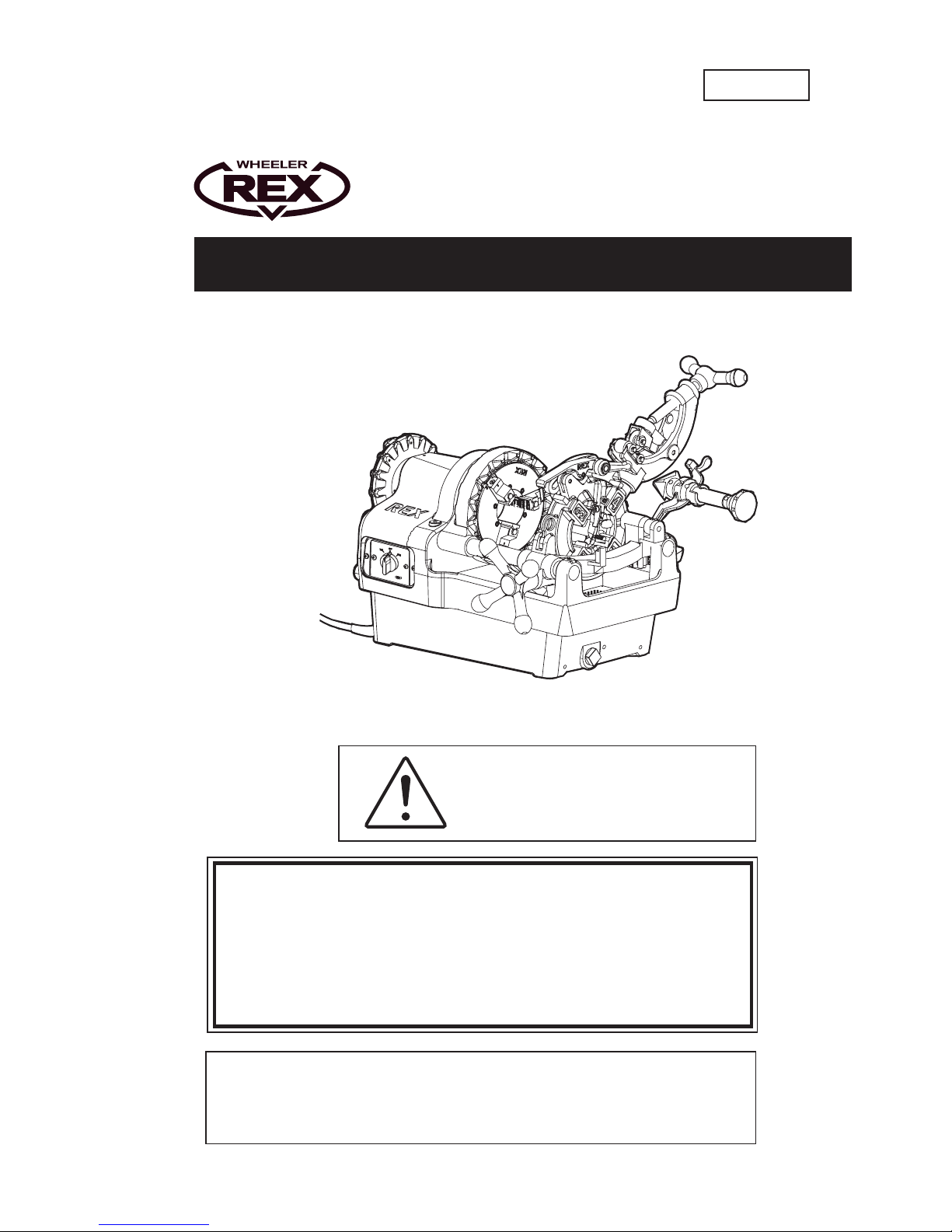
Thank you for purchasing a WHEELER REX pipe threading machine.
Precision-engineered for cutting, reaming, threading and, with our optional Portable Groovers, grooving
steel and stainless steel (option) pipes, our product will give you years of reliable service if you simply
follow the instructions in this manual carefully.
Before using the machine, therefore, make sure you read the manual from start to finish, paying particular
attention to the Safety Considerations on pages 1 & 2 and Precautions on pages 3 & 4. To avoid accident
and injury, never use the machine for any purposes other than those described in this manual.
Should you need further advice, contact your distributor or WHEELER REX.
Definitions of and
In this operation manual, warnings are divided into and .
: indicates actions which could possibily result in death or severe injury to the user
if the machine is used incorrectly.
: indicates actions which could possibly result in injury to the user, or physical
damage, if the machine is used incorrectly.
Even items described as could have serious results under certain conditions.
Be sure to observe these warnings carefully as they greatly affect safety.
- If this operation manual is lost or damaged, promptly order a replacement from your distributor or our sales
department.
- Parts and specifications are subject to change without prior notice, due to improvements in quality,
performance or safety standards. In such cases, the contents, photographs, illustrations, etc. in this
manual may be different to the product you have purchased.
!WARNING !CAUTION
!WARNING !CAUTION
!CAUTION
!WARNING
!CAUTION
CONTENTS
Safety Considerations
.............................................................................
.
1
Precautions
.........................................................................................
3
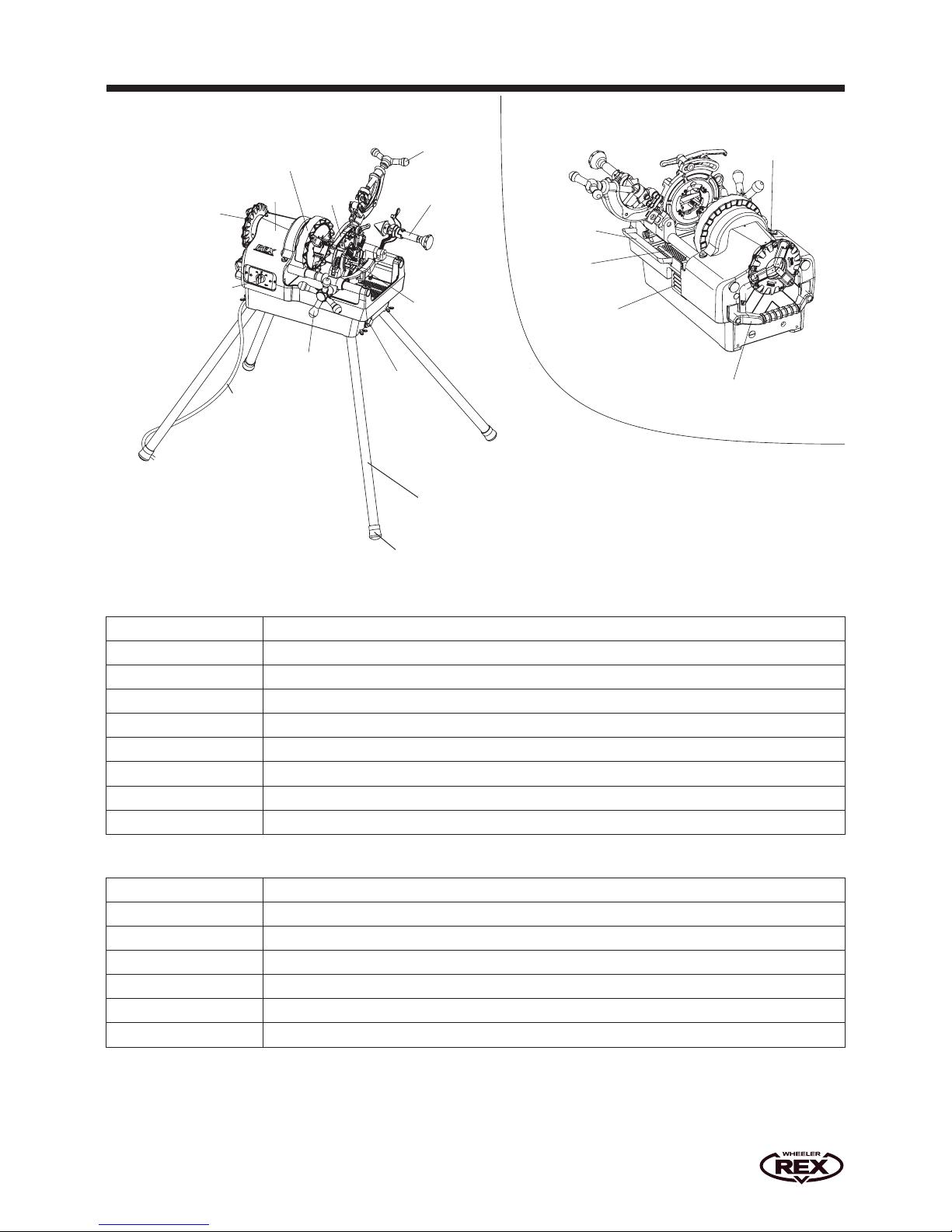
Main Parts, Specifications, Standard Accessories, Usage
....................................
.
5
Getting
Ready
1. Transportation
..............................................................................
6
2. Machine set up
.............................................................................
6
3. Thread cutting oil
..........................................................................
6
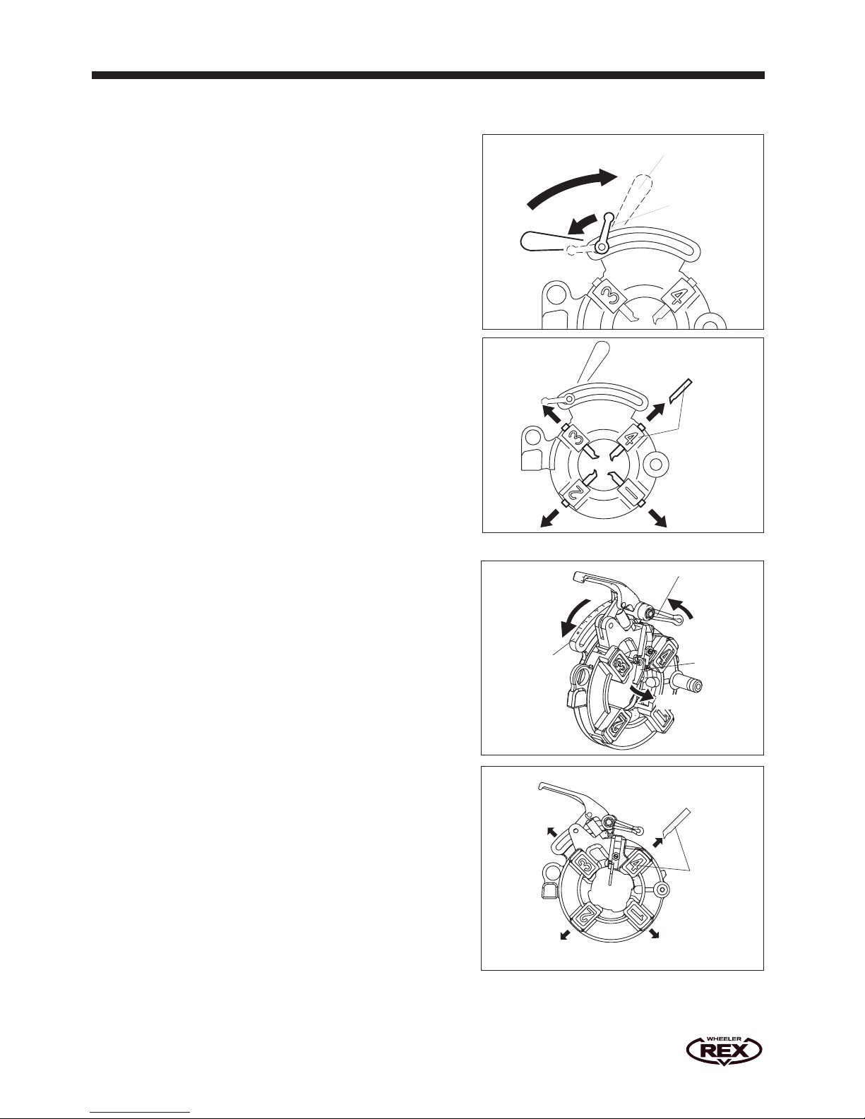
4. Attaching the die head
....................................................................
6
5. Operating the die Head
....................................................................
7
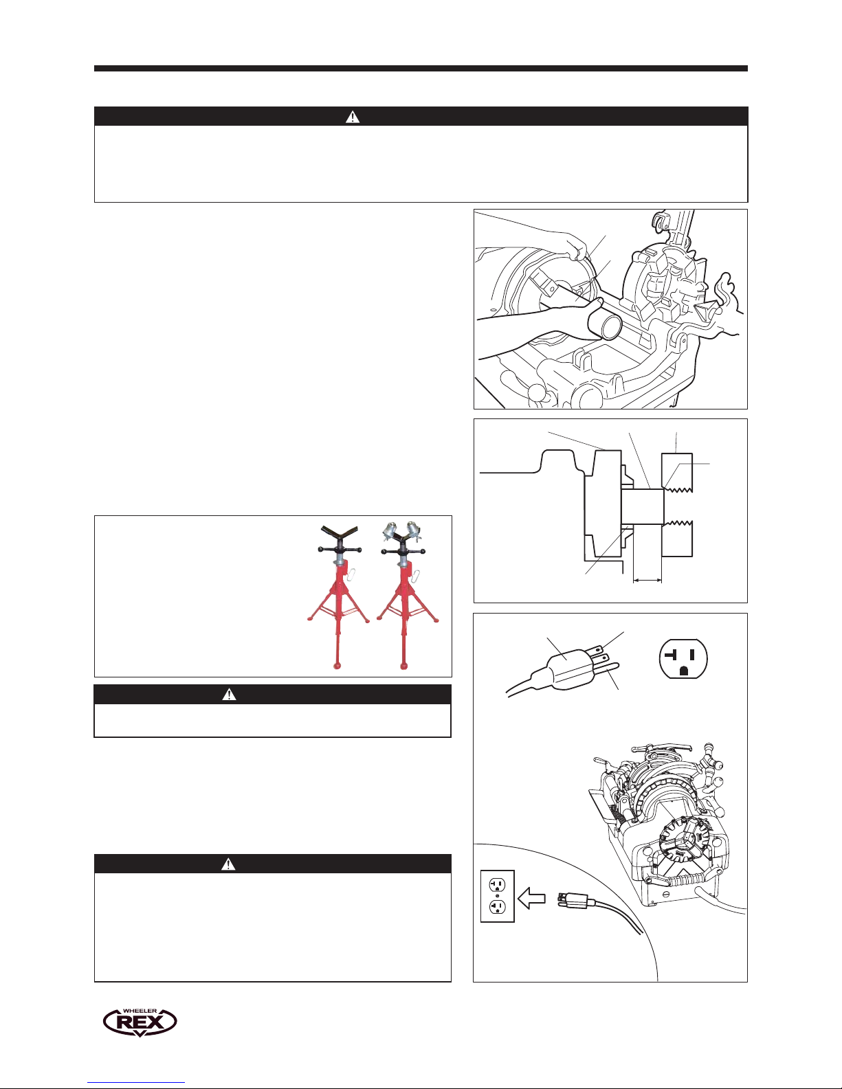
6. Setting up the pipe/Removing the pipe
..................................................
8
7. Power supply
..............................................................................
8
8. Check before starting
.....................................................................
.9
9. Cutting pipe
...............................................................................
.9
10. Reaming/Points to watch when threading
.............................................
.
10
Operation Guide
11. Making threads (Optional Manual-open Die Head)
....................................
11
12. Adjusting the oil flow
.....................................................................
.
11
13. Making threads (NV-auto Die Head)
...................................................
.
12
14. Measuring threads with a gauge/Precautions when threading
.....................
13
Optional Accessories
.............................................................................
14
Maintenance and Care
1. Grease, Oil
................................................................................
.
15
2. Replacing the carbon brushes
..........................................................
.
15
3. Cleaning the oil tank
.....................................................................
16
4. Replacing/Installing the chuck jaw set
...............................................
.
16
5. Wiring diagram
............................................................................
16
Service and Repairs
............................................................................
16
Troubleshooting
...................................................................................
17