Wheelock AHWP Series User manual

Description:
Wheelock’s Weatherproof Strobe, Audible Strobe, Multitone
Strobe and Audible appliances all have an extended
temperature range of -35°C to 66°C (-31°F to 150°F) and will
satisfy virtually all outdoor and severe environment
applications. AllstrobesareIndoor/OutdoorULListedandrated
for75candela @-35°C(-31°F).
SeriesRSSWPStrobes,SeriesASWPAudibleStrobes Series
AHWP Audibles and Series MTWP Strobe may be
synchronized when used in conjunction with the Wheelock
SM and DSM Sync Module(s).
Weatherproof Strobes - Series RSSWP
ULCListedunderStandardCAN/ULC-S526-02for
Indoor/Outdooruse. Thestrobes useaXenon flashtubewith
solidstatecircuitryenclosedinaruggedLexan® lens to provide
maximum visibility and reliability for effective visual signaling.
TheSeries RSSWPhas a 75 cd intensityon axisat -35°Cand
Low Current Draw (180 cd @ 25°C). For outdoor application
theRSSWP must bewall mountedtoa Weatherproofbackbox
(WPSBB).
WeatherproofAudibleStrobesand Audibles- Series ASWP
and AHWP
ULC Listed under Standard CAN/ULC-S526-02 for Visual
Signaling Appliances and Standard CAN/ULC-S525-99 for
AudibleSignalingAppliances. Indoor/Outdoor useand offera
field selectable choice of continuous horn or temporal pattern
(Code 3) when constant voltage from the Fire Alarm Control
Panel(FACP)isapplied. Additionally,theaudible hasthree (3)
selectable dBA settings of 99, 95, and 90 dBA in both tones
and, when used with Wheelock sync modules, SM or DM the
audible may be silenced while maintaining strobe activation
on the Series ASWP. For outdoor applications the ASWP
mustbe WallMounted tothe WeatherproofBackbox (WPBB).
Weatherproof Multitone Strobe and Multitone Horn -
Series MTWP and MT-12/24
Is ULC Listed for indoor and outdoor applications under
Standard CAN/ULC-S526-02 for Visual Signaling and under
StandardCAN/ULC-S5255-99forAudibleSignalDevicesforFire
AlarmSystems. TheMultitone StrobeAppliances useaXenon
flashtubewithsolidstate circuitry enclosedinaruggedLexan®
lens to provide maximum visibility and reliability for effective
visible signaling. The Multitone electronic appliance offers a
choice of eight (8) internationally recognized alerting sounds:
Horn,Bell, MarchTimeHorn, Code 3Tone,Code 3 Horn,Slow
Whoop, Siren or Hi/Lo Tone. Additionally, the audible has two
installer selectable sound output levels; Standard and High
coveringarange(dependingon selected signal)or85-100dBA
anechoic. The series MTWP is a true 4-wire appliance. The
strobeportioncanbysynchronizedandnon synchronized. The
Multitone (audible) portion can be synchronized, but it can be
connected to a coded fire alarm system. The series MTWP
and the MT-12/24 mount to a series IOB out door backbox.
SERIES RSSWP, ASWP, AHWP, and MTWP
WEATHERPROOF STROBE
WEATHERPROOF AUDIBLE STROBE
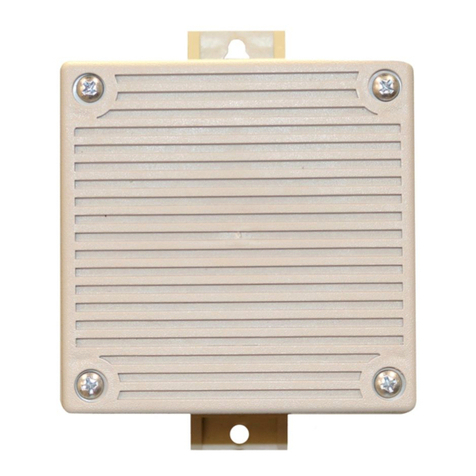
WEATHERPROOF AUDIBLE HORN
FEATURES
•Approvals include: ULC, UL 1638, UL 464
•Meets OSHA 29 Part 1910.165.
•ULC Listed with an extended temperature range
of -35°C to 66°C (-31°F to 150°F).
•24 VDC with wide UCL Listed Voltage
Range using filtered (DC) or unfiltered VRMS
voltage.
•Synchronize with Wheelock Series SM or DSM,
Sync Module(s).
SERIES RSSWP
Mounted to WPSBB
SERIES ASWP
Mounted to WPBB
FIRE ALARM SYSTEMS
SERIES AHWP
SERIES MTWP
Mounted to IOB
Copyright2005Wheelock,Inc. All rights reserved. 36
INC.
Helping People Take Action
SM

NOTE: All CAUTIONS and WARNINGS are identified by the symbol All WARNINGS are printed in bold capital letters.
WARNING: PLEASE READ THESE SPECIFICATIONS AND ASSOCIATED INSTALLATION INSTRUCTIONS CAREFULLY
BEFORE USING, SPECIFYING OR APPLYING THIS PRODUCT. FAILURE TO COMPLY WITH ANY OF THESE
INSTUCTIONS, CAUTIONS, OR WARNINGS COULD RESULT IN IMPROPER APPLICATION, INSTALLATION, AND/OR
OPERATION OF THESE PRODUCTS IN AN EMERGENCY SITUATION, WHICH COULD RESULT IN PROPERTY DAMAGE,
AND SERIOUS INJURY OR DEATH TO YOU AND/OR OTHERS.
*tnerruCCLU:3elbaT PWHAseireSrof)SPMA( egatloVPW42-HA
PW42-HAwoL/deM/iH
CDV0.02 410./020./530.
CDV0.42 710./52
0./050.
CDV0.13 120./030./560.
dnaPWSSRseireSrof*tnerruCegarevA:1elbaT PWTMniebortS
ledoM )dc57( detalugeR egnaRegatloV
*tnerruC.gvA
0.02 CD
V0.42 CDV 0.13 CDV
RF-W5742-PWSSRCDV0.13-0.02831.490.760.
PWHA&PWSAseireSrofsgnitaRABd:4elbaT
noitpircseDemuloV ABdtnarebreveR .tf01@464LUreP ABdciohcenA .tf01@
CDV42C
DV42
suounitnoC nroH
hgiH1999
deM8859
woL2809
3edoC nroH
hgiH5899
deM2859
woL5709
* Average current per actual Wheelock production testing.
For rated average, peak and in rush current across the UL listed voltage range
for both filtered DC and unfiltered VRMS, see Installation Instructions.
#Audible and Visual combined.
General Notes:
•Wheelock CAN/ULC-S526-M87 Strobes are designed to produce 30-62 flashes per minute over the Voltage Range.
•Series RSSWP, AHWP, MTWP and MT12/24 are listed for indoor and outdoor use with a temperature range of -35°C to 66°C (-31°F to
150°F) and maximum humidity of 93% RH ±2%. SeriesAHWP temperature range -35°C to 66°C (-31°F to 150°F) and maximum humidity of
98%RH±2%.
•All Canadian Installations should be in accordance with the Canadian Standard for the Installation of Fire Alarm Systems -
CAN/ULC-S524-01 and Canadian Electrical Code, Part 1.
)SPMA(*tnerruCegarevA:2elbaT ebortSelbiduARF-W5742-PWSAseireSroF
egatloV ABdhgiH gnitteS ABd)99(
ABdmuideM g
nitteS ABd)59(
ABdwoL gnitteS ABd)09(
CDV0.02861.551.051.
CDV0.42231.901.201.
CDV0.13321.090.080.
PWTMseireSCDV,42rof)SPMA(sgnitaRtnerruCCLU:5elbaT
CDV0.02CDV0.42CDV0.13
detaRCLU egarevA tnerruC 831.0490.0760
.0
enoTdradnatShgiHdradnatShgiHdradnatShgiH
nroH120.0630.0320.0040.0920.0050.0
lleB110.0310.0210.0410.0510.0810.0
emiThcraM1
20.0630.0320.0040.0920.0050.0
nroH3edoC120.0630.0320.0040.0920.0050.0
enoT3edoC510.0520.0710.0820.0120.0530.0
poohWwolS320
.0340.0620.0840.0330.0060.0
neriS120.0230.0320.0630.0920.0540.0
oL/iH310.0810.0410.0020.0810.0520.0
37

sgnitaRCLU:8elbaT
ledoM
lanimoN egatloV -RV/CDV( )SM
detalugeR tupnI )CDV42(
detalugeR tupnI )CDV21(
ebortS aledna
CCLUreP
W5742-PWSA420.13-0.02-57
R-PW42-HA420.13-0.02--
W5742-PWSSR420.13-0.02-57
W5742-PWTM420.13-0.02-57
42/21-TM420.13-0.
026.51-0.9-
seireSrof)SPMA(sgnitaR*tnerruCCLU:6elbaT PWTMfoelbiduadna42/21-TM
enoTCDV0.21CDV0.42
dradnatShgiHdradnatShgiH
nroH020.0001.0320.0040.0
lleB010.0130.0210.0410.0
emiThcraM020.0001.0320.0040.0
nroH3edoC020.0001.0320.0040.0
enoT3edoC510
.0060.0710.0820.0
poohWwolS520.0001.0620.0840.0
neriS020.0280.0320.0630.0
oL/iH210.0440.0410.0020.0
ABdCDV42CLU:7elbaT rePsgnitaRciohcenA teeF01ta99-525SCLU/NAC
enoT V42
IHDTS
nroH 9939
lleB 2978
emiThcraM 9939
nroH3e
doC 9939
enoT3edoC 5909
poohWwolS 9949
neriS 8939
OL/IH 3988
38

SERIES MTWP AUDIBLE APPLIANCE AND STROBE OPERATE
IN UNISON. RED AND BLACK SHUNT-WIRES ARE SUPPLIED.
TO NEXT
APPLIANCE
OR EOLR
FROM
PRECEDING
APPLIANCE
OR FACP
+-
STROBE AUDIBLE
+-
RED
BLACK
+
--
+
Wiring Diagrams
SERIES MTWP AUDIBLE APPLIANCE AND STROBE OPERATE
INDEPENDENTLY
TO NEXT
AUDIBLE OR
EOLR
FROM
PRECEDING
AUDIBLE OR
FACP
TO NEXT
STROBE OR
EOLR
FROM
PRECEDING
STROBE OR
FACP
AUDIBLESTROBE
+-- +
+
-
--
-
++
+
+
-
+-
+
-
FROM
PRECEDING
APPLIANCE OR
FACP
TO NEXT
APPLIANCE
OR EOLR
SERIES RSSWP, ASWP, AHWP, MTWP AND MT-12/24
APPLIANCES
APPLIANCE
39

TO THE NEXT
APPLIANCE
OR EOLR
DSM
+ OUT 2
+OUT 1
+ IN 1
+ IN 2
MINUS 1
MINUS 2
+
-
-
+
SYNC
AUDIBLE
STROBE
NAC
CIRCUIT
OUT
STROBE
NAC
CIRCUIT
RETURN
FACP
RSSWP RSS
RSS RSS
ASWP
ASWP
SERIES RSSWP/ASWP APPLIANCES SYNCHRONIZED W/
DSM MODULE SINGLE CLASS “A” NAC CIRCUIT
SERIES RSSWP/ASWP APPLIANCES SYNCHRONIZED
W/MULTIPLE DSM MODULES CLASS “B” NAC CIRCUITS
F
A
C
PDSM #3
Strobe NAC Cir.
DSM #2
DSM #1
Strobe NAC Cir.
Strobe NAC Cir.
Sync
Sync
Sync
+
-
+
+
-
-
DSM Interconnecting wiring shown. Maximum of
twenty (20)
RSSWP RSS
RSSWP
RSSWP RSSWP
ASWP
Wiring Diagrams
FACP
+
-
SYNC
NAC #1
NAC #2
Sync
Module
or
Power
Supply
Strobe
Circuit
Audible
Circuit
MTWP
SERIES MTWP APPLIANCES SYNCHRONIZED
STROBE OPERATION WITH CODED FACP
40

ledoM redrO edoC -noN cnyS
,MS/wcnyS MSD dcebortS C°53-@ )F°13-( ABd tupnI egatloV
roodtuO gnitnuoM *snoitpO
ebortS RF
-W5742-PWSSR3109seYseYdc57- CDV42T
WF-W5742-PWSSR4303seYseYdc57- CDV42T
WN-W5742-PWSSR8779seYseYdc57- CDV42T
ebortSelbiduA RF-W57
42-PWSA2109seYseYdc5799/59/09CDV42I
ebortSenotitluM RF-W5742-PWTM0248seYylnOebortS,seYdc5749-57CDV42M
WF-W5742-PWTM2113s
eYylnOebortS,seYdc5749-57CDV42M
WN-W5742-PWTM4479seYylnOebortS,seYdc5749-57CDV42M
selbiduA/snroH R-PW42-HA6147seYseYA/N99
/59/09CDV42K
R-42/21-TM3205seYoNA/NM
sexoBkcaBU
SE
W
ITH
R-BBSPW1579PWSSR
R-BBPW4109PWSA
R-BOI6405 &PWTM R-42/21-TM
R-BBW9592PWHA
SPECIFICATIONS AND ORDERING INFORMATION
*Refer to data sheet S7000 for mounting options
WARNING: CONTACT WHEELOCK FOR THE CURRENT “INSTALLATION INSTRUCTIONS” AND
“GENERAL INFORMATION” SHEET (P82380) ON THESE PRODUCTS. THE INSTALLATION INSTRUCTIONS
ARE AS FOLLOWS: P84135 FOR SERIES RSSWP, P83957 FOR SERIES ASWP, P83641 FOR SERIES
AH-WP, P84150 FOR SEREIS MTWP AND P824671 FOR SERIES MT-12/24-R. THESE DOCUMENTS
UNDERGO PERIODIC CHANGES. IT IS IMPORTANT THAT YOU HAVE CURRENT INFORMATION ON THESE
PRODUCTS. THESE MATERIALS CONTAIN IMPORTANT INFORMATION THAT SHOULD BE READ PRIOR TO
SPECIFYING OR INSTALLING THESE PRODUCTS, INCLUDING:
•TOTAL CURRENT REQUIRED BY ALL APPLIANCES CONNECTED TO SYSTEM SECONDARY POWER
SOURCES.
•FUSE RATINGS ON NOTIFICATION APPLIANCE CIRCUITS TO HANDLE PEAK CURRENTS FROM ALL
APPLIANCES ON THOSE CIRCUITS.
•ADDING, REPLACING OR CHANGING APPLIANCES WILL EFFECT CURRENT DRAW. RECALCULATE
CURRENT DRAW TO INSURE THAT THE TOTAL AVERAGE CURRENT AND TOTAL PEAK REQUIRED BY
ALL APPLIANCES DO NOT EXCEED THE RATED CAPACITY OF THE POWER SOURCE OR FUSES.
•COMPOSITE FLASH RATE FROM MULTIPLE STROBES WITHIN A PERSON’S FIELD OF VIEW.
•THE VOLTAGE APPLIED TO THESE PRODUCTS MUST BE WITHIN THEIR “REGULATED VOLTAGE
RANGE”.
•USE STROBES ONLY ON CIRCUITS WITH CONTINUOUSLY APPLIED OPERATING VOLTAGE. DO NOT
USE STROBES ON CODED OR INTERRUPTED CIRCUITS IN WHICH THE APPLIED VOLTAGE IS CYCLED
ON AND OFF AS THE STROBE MAY NOT FLASH.
•FAILURE TO COMPLY WITH THE INSTALLATION INSTRUCTIONS OR GENERAL INFORMATION SHEETS
COULD RESULT IN IMPROPER INSTALLATION, APPLICATION, AND/OR OPERATION OF THESE
PRODUCTS IN AN EMERGENCY SITUATION, WHICH COULD RESULT IN PROPERTY DAMAGE AND
SERIOUS INJURY OR DEATH TO YOU AND/OR OTHERS.
•CONDUCTOR SIZE (AWG), LENGTH AND AMPACITY SHOULD BE TAKEN INTO CONSIDERATION PRIOR
TO DESIGN AND INSTALLATION OF THESE PRODUCTS, PARTICULARLY IN RETROFIT
INSTALLATIONS.
41

NotificationAppliance Circuit
Layout and Design
Project
No.
By Date
42

The Weatherproof Strobe appliances shall be Wheelock Series RSSWP-2475W strobes or approved equals. The
SeriesRSSWPshallmeet andbe listed forULC andS526-02 Standard1638(StandardforVisualSignalingAppliances)
forIndoor/Outdoor use. The strobeappliances shallproducea flashrate of30-62flashes perminute over theRegulated
VoltageRangeof 20.0 to31.0VDCandshall incorporate aXenonflashtubeinclosed in aruggedLexan®lens. Thestrobe
shallberated at75cdand shall operateoveran extendedtemperaturerange of -35°Cto66°C (-31°Fto150°F). All inputs
shall be polarized for compatibility with standard reverse polarity supervision of circuit wiring by a Fire Alarm Control
Panel. When synchronization is required, the appliances shall be compatible with the Wheelock Series SM and DSM
SyncModule(s). The strobes shall not drift out of synchronization at any time during operation. If the sync modulefails
to operate, (i.e., contacts remain closed), the strobe shall revert to a non-synchronized flash rate.
The Weatherproof Audible Strobe and Audible appliances shall be Wheelock Series ASWP-2475W Audible Strobes
and Wheelock Series AHWP Audible Horns or approved equals. The Series ASWP and Series AHWP shall meet and
be listed for ULC and S526-02 Standard 1638 (Standard for Visual SignalingAppliances) for Indoor/Outdoor use. The
strobeappliancesshall produce aflashrate of 30-62flashesperminute overtheRegulatedVoltageRangeof20.0 to 31.0
VDCand shallincorporate a Xenon flashtube enclosedin arugged Lexan®lens. The strobe shall be rated at 75cdand
shall operate over an extended temperature range of -35°C to 66°C (-31°F to 150°F). All inputs shall be polarized for
compatibilitywith standardreverse polaritysupervision ofcircuit wiringby aFireAlarmControl Panel (FACP).
Theweatherproofaudiblestrobeappliances shall bedesignedfortwo-wireoperationand shall provideeitheracontinuous
or temporal (Code 3) tone when constant voltage from a Notification Appliance Circuit (NAC) of the Fire Alarm Control
Panel (FACP) is applied. They shall be designed so that the audible signal may be silenced while maintaining strobe
activation. When synchronization is required, the appliances shall be compatible with the WheelockSeries SM and
DSM Sync Module(s). The strobes shall not drift out of synchronization at any time during operation. If the sync fails
to operate, (i.e., contacts remain closed), the strobe shall revert to a non-synchronized flash rate.
The Weatherproof Multitone Strobe and Multitone Audible appliances shall be a Wheelock Series MTWP and
MT-12/24 or equivalent. The Series MTWP shall meet and be listed for ULC and S526-02 Standard 1638 (Standard for
Visual SignalingAppliances)forindoor/outdooruse. The strobeportion of theappliance shallproduce aflash rate of30-
62flashes perminute overthe listedvoltage rangeof 20-31 VDC and shall incorporate aXenon flashtube enclosedin a
ruggedLexan® lens. Thestrobe shallbe ratedat 75cd. Theseries MTWPshall operateover anextended temperature
range of -35°C to 66°C (-31°F to 150°F). All inputs shall be polarized for compatibility with industry standard reverse
polarityof circuitwiringby aFireAlarm ControlPanel. The audibleportion of theSeries MTWPaswellas theSeries MT-
12/24 shall provide eight field selectable alarm signals. The signals shall consists of: Horn, Bell, March Time, Code 3
Horn, Code 3 Tone, Slow Whoop, Siren and Hi/Lo. Tone selection shall be by a durable dip switch assembly. Clips or
Jumpersarenot acceptable. Theapplianceshallprovidetwo output soundlevels: StandardandHighdBA. Therange of
dBAshallbe 75to 94dBA. The SeriesMTWPshallhave anoperating voltageof24 VDC(nominal) while theSeries MT-
12/24 shall operate at either 12 or 24 VDC (nominal) using filtered power or unfiltered power (full wave rectified). Both
modelsshallhaveprovisionsforIn/Outfieldwiringusingterminalsthataccept#12to#18AWGwiring. Whensynchronization
is required, the Series MTWP shall be compatible with the Series SM and DSM Sync Modules. Note: The Strobe
portion of the Series MTWP may be synchronized. The audible portion of the appliance cannot. The audible
portion of the appliance can be connected to a coded fire alarm system. The Series MTWP and the Series
MT-12/24 shall be mounted only to the IOB-R Backbox.
ARCHITECTS AND ENGINEERS SPECIFICATIONS
NATIONAL SALES OFFICE
800-631-2148
Canada 800-397-5777
E-Mail: [email protected]
http://www.wheelockinc.com
273 BRANCHPORT AVENUE •LONG BRANCH, NJ 07740 •TEL: 732-222-6880 •FAX: 732-222-2588
WE ENCOURAGE AND SUPPORT NICET CERTIFICATION
ASSEMBLED IN THE USA
3 YEAR WARRANTY Distributed By:
Due to continuous development of our products, specifications and offerings are subject to change without notice in accordance
with Wheelock Inc. standard terms and conditions.
S9004C Rev 02/05
43
This manual suits for next models
3
Table of contents
Other Wheelock Security System manuals

Wheelock
Wheelock SERIES SM User manual

Wheelock
Wheelock RX-1419 User manual

Wheelock
Wheelock TB-593 User manual

Wheelock
Wheelock RS-2415 User manual

Wheelock
Wheelock MZC-144 User manual

Wheelock
Wheelock NS-1215W User manual

Wheelock
Wheelock TBM User manual

Wheelock
Wheelock SAFEPATH SCSP-15SP User manual

Wheelock
Wheelock UTA-1 User manual

Wheelock
Wheelock SAFEPATH SAPE-1AB Specification sheet