manuals.online logo
Brands
  1. Home
  2. •
  3. Brands
  4. •
  5. Whelen Engineering Company
  6. •
  7. Controllers
  8. •
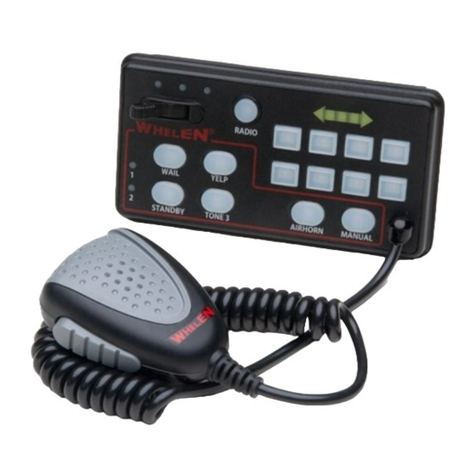
  9. Whelen Engineering Company Wireless Traffic Advisor Operating and maintenance instructions

Whelen Engineering Company Wireless Traffic Advisor Operating and maintenance instructions

Page 1
Installation Guide:
Wireless Traffic Advisor™ Controller
©2006 Whelen Engineering Company Inc.
Form No.14059C (102607)
®
ENGINEERING COMPANY INC.
Automotive: Traffic Advisor
For warranty information regarding this product, visit www.whelen.com/warranty
51 Winthrop Road
Chester, Connecticut 06412-0684
Phone: (860) 526-9504
Fax: (860) 526-4078
Internet: www.whelen.com
Sales e-mail: autosale@whelen.com
Canadian Sales e-mail: autocan@whelen.com
Customer Service e-mail: custserv@whelen.com
Safety First
This document provides all the necessary information to allow your Whelen product to be properly and safely installed.
Before beginning the installation and/or operation of your new product, the installation technician and operator must
read this manual completely. Important information is contained herein that could prevent serious injury or damage.
• Proper installation of this product requires the installer to have a good understanding of automotive electronics,
systems and procedures.
• If mounting this product requires drilling holes, the installer MUST be sure that no vehicle components or other
vital parts could be damaged by the drilling process. Check both sides of the mounting surface before drilling
begins. Also de-burr any holes and remove any metal shards or remnants. Install grommets into all wire
passage holes.
• If this manual states that this product may be mounted with suction cups, magnets, tape or Velcro®, clean the
mounting surface with a 50/50 mix of isopropyl alcohol and water and dry thoroughly.
• Do not install this product or route any wires in the deployment area of your air bag. Equipment mounted or
located in the air bag deployment area will damage or reduce the effectiveness of the air bag, or become a
projectile that could cause serious personal injury or death. Refer to your vehicle owner’s manual for the air bag
deployment area. The User/Installer assumes full responsibility to determine proper mounting location, based
on providing ultimate safety to all passengers inside the vehicle.
• For this product to operate at optimum efficiency, a good electrical connection to chassis ground must be
made. The recommended procedure requires the product ground wire to be connected directly to the NEGATIVE
(-) battery post.
• If this product uses a remote device to activate or control this product, make sure that this control is located in
an area that allows both the vehicle and the control to be operated safely in any driving condition.
• Do not attempt to activate or control this device in a hazardous driving situation.
• This product contains either strobe light(s), halogen light(s), high-intensity LEDs or a combination of these
lights. Do not stare directly into these lights. Momentary blindness and/or eye damage could result.
• Use only soap and water to clean the outer lens. Use of other chemicals could result in premature lens cracking
(crazing) and discoloration. Lens in this condition have significantly reduced effectiveness and should be
replaced immediately. Inspect and operate this product regularly to confirm its proper operation and mounting
condition. Do not use a pressure washer to clean this product.
• It is recommended that these instructions be stored in a safe place and referred to when performing
maintenance and/or reinstallation of this product.
• FAILURE TO FOLLOW THESE SAFETY PRECAUTIONS AND INSTRUCTIONS COULD RESULT IN DAMAGE TO
THE PRODUCT OR VEHICLE AND/OR SERIOUS INJURY TO YOU AND YOUR PASSENGERS!
Page 2
= Receiver Location (typical)
= Receiver Location
Note! This controller will only work with Traffic Advisor™
models that have been equipped at the factory with
wireless receivers.
Battery Installation
1. Remove the 4 Phillips head screws that secure the back
cover onto the controller. Remove and retain the screws
and cover from the controller.
2. Locate and install the two (2) AAA size batteries included
with the controller. Be sure to install the batteries so that
their orientation and polarity match the battery outline on
the circuit board.
3. Return the rear cover to its original position and secure it
onto the controller using the screws removed in step 1.
-
+-
+
Binding Procedure
The Traffic Advisor and its controller are pre-bound at the
factory to work right out of the box. However, if either of these
are replaced, the binding procedure must be performed
before the Traffic Advisor and its controller can be put into
service.
The binding procedure will configure the controller so that it
will only operate the Traffic Advisor to which it is bound. Keep
in mind that a controller can not be bound to more than one
Traffic Advisor at a time.
1. Turn the power to the Traffic Advisor on. There should be
no pattern displayed during this procedure.
2. Locate the receiver module mounted on the Traffic
Advisor array. On arrow-style arrays this module is
typically located in the upper-left section of the array as
shown.
1. On bar-style arrays, the receiver module is mounted on
the endcap as shown.
2. Place and hold the controller against the receiver
module. Make sure that the LED indicators on the
controller can clearly be seen. The controller MUST
remain in contact with the receiver module during
the entire binding procedure (70 seconds max.)
3. Input the following sequence on the controller.
IMPORTANT! Do not allow more than one (1) second
between key presses!
Binding Sequence
S/L > S/L > S/L > Left Arrow > S/L > Right Arrow > S/L
If this sequence has been successfully entered, the center
LED indicator will flash to indicate that the binding process
has begun. This process will last a maximum of seventy (70)
seconds.
If the binding procedure is successful, the center three (3)
LED indicators will simultaneously flash for three (3) seconds.
Test the controller to confirm proper operation.
If the binding procedure is unsuccessful, the center LED will
stop flashing. In this event, wait for the controller backlight to
go out and repeat the binding procedure from the beginning.
If the binding procedure is unsuccessful after 2 more
attempts, contact Whelen Customer Service.
Page 3
S/L
OFF
LED
Indicators
Left
Arrow
Right
Arrow
Split
Arrow
Scan-Lock™
Flash
Of
f
Button
Operation
As shown here, the controller is comprised of six (6) buttons
and 5 LED indicators
Arrow Buttons - There are three Arrow buttons; Left, Right
and Split. Pressing these buttons will initiate their designated
sequence. There are five (5) different sequence styles in
which these sequences are displayed. The selected
sequence style is applied to all three arrow buttons.
The sequence style selected will be used for all three buttons.
The 5 styles are as follows:
Solid Arrow (default)
Solid Half Arrow
Sequence to TripleFlash™
Sequence to Solid
Sequence On / Sequence Off
For information on changing styles, please refer to the “Scan-
Lock” section of this manual.
Flash Button - The Flash button will activate one of three (3)
available displays. They are as follows:
Flash Tips (default)
Flash Bar
Flash Tips and Bar
For information on changing displays, please refer to the
“Scan-Lock” section of this manual.
Scan-Lock - The Scan-Lock button is used to change the
styles used for the Arrow buttons and the display used by the
Flash button. This button operates as follows:
1. Press and hold the desired Arrow (Left, Right, Split) or
Flash button.
2. While holding the Arrow or Flash buttons, press and hold
the Scan-Lock (S/L) button for less than one (1) second
and release. This will advance the current style or
display to the next style or display.
3. Release the Scan-Lock button and allow the selection to
run for a minimum of 5 seconds to designate it the
default style/display.
IMPORTANT! In areas where the type of pattern
displayed is mandated by State, County or Municipal
authorities, this function may be disabled. In these
regions, the Scan-Lock button will still be used for the
binding procedure.
Off - The Off button is used to turn off the Traffic Advisor™.
LED Indicators - There are five (5) LED Indicators located
on the face of the controller. These LEDs provide a brief
visual representation of the Sequence or Display selected.
These indicators also provide important information during
the Binding process. Refer to the “Binding Procedure”
section for more information.
Backlight - The controller features backlighting to aid
nighttime operation. Backlighting is activated whenever any
button is pressed and will remain on for approximately 3
seconds after the last button press.
Low Battery Indicator - When it is time to replace the
controller batteries, the OFF button will periodically flash red.
If this behavior is noticed, replace the batteries immediately.
Controller Mounting Clip - A mounting clip is included with
this controller. This provides a place for the operator to keep
the controller when it is not in use. When determining a
mounting location for this clip, it is important to select a
location that does not place either the clip or the clip/
controller where it could interfere with any existing
equipment.
IMPORTANT AIR BAG WARNING! Do not install this
product in the air bag deployment zone of your vehicle.
Equipment mounted or located in air bag deployment
zones will damage or reduce the effectiveness of the air
bag, or become a projectile that could cause serious
personal injury or death. Refer to your vehicle owners
manual to learn the air bag deployment zones for the
vehicle. The User/Installer assumes full responsibility to
determine proper mounting location, based on providing
ultimate safety to all passengers inside the vehicle.

Other Whelen Engineering Company Controllers manuals

Whelen Engineering Company MPC01 User manual

Whelen Engineering Company

Whelen Engineering Company MPC01 User manual

Whelen Engineering Company MPC02 User manual

Whelen Engineering Company

Whelen Engineering Company MPC02 User manual

Whelen Engineering Company MPC01 User manual

Whelen Engineering Company

Whelen Engineering Company MPC01 User manual

Whelen Engineering Company MGC02 Manual

Whelen Engineering Company

Whelen Engineering Company MGC02 Manual

Whelen Engineering Company MPC-NFPA User manual

Whelen Engineering Company

Whelen Engineering Company MPC-NFPA User manual

Whelen Engineering Company MPC03 Troubleshooting guide

Whelen Engineering Company

Whelen Engineering Company MPC03 Troubleshooting guide

Whelen Engineering Company MPC02 User manual

Whelen Engineering Company

Whelen Engineering Company MPC02 User manual

Whelen Engineering Company MPC01 User manual

Whelen Engineering Company

Whelen Engineering Company MPC01 User manual

Whelen Engineering Company 295SHA1 User manual

Whelen Engineering Company

Whelen Engineering Company 295SHA1 User manual

Whelen Engineering Company 295SSA1 User manual

Whelen Engineering Company

Whelen Engineering Company 295SSA1 User manual

Popular Controllers manuals by other brands

Minarik MM23001C quick start guide

Minarik

Minarik MM23001C quick start guide

Bosch Worcester Digital Twin Channel Programmer Installation & operating instructions

Bosch

Bosch Worcester Digital Twin Channel Programmer Installation & operating instructions

Siemens KNX RL 524D23 quick start guide

Siemens

Siemens KNX RL 524D23 quick start guide

Emerson White-Rodgers 21M51U-843 installation instructions

Emerson

Emerson White-Rodgers 21M51U-843 installation instructions

Simex MultiCon CMC-N16 user manual

Simex

Simex MultiCon CMC-N16 user manual

National Instruments ExpressCard-8360 installation guide

National Instruments

National Instruments ExpressCard-8360 installation guide

PhaseOne iX MK 5 Installation and operation guide

PhaseOne

PhaseOne iX MK 5 Installation and operation guide

Agilent Technologies Turbo-V 550 instruction manual

Agilent Technologies

Agilent Technologies Turbo-V 550 instruction manual

Kicker PXi50.2 owner's manual

Kicker

Kicker PXi50.2 owner's manual

INCOE VGC instruction manual

INCOE

INCOE VGC instruction manual

Zennio ZN1VI-TPZAS product manual

Zennio

Zennio ZN1VI-TPZAS product manual

Johnson Controls VMA1200 Series Mounting and wiring instruction

Johnson Controls

Johnson Controls VMA1200 Series Mounting and wiring instruction

Woodward AtlasPC Hardware manual

Woodward

Woodward AtlasPC Hardware manual

Woertz DALI 2 Operation manual

Woertz

Woertz DALI 2 Operation manual

Texas Instruments DRV8833 manual

Texas Instruments

Texas Instruments DRV8833 manual

DPS Telecom NetGuardian 832A G5 user manual

DPS Telecom

DPS Telecom NetGuardian 832A G5 user manual

TOPP ACK4S Series Installation and use instructions

TOPP

TOPP ACK4S Series Installation and use instructions

SOMFY Animeo KNX RS485 operating manual

SOMFY

SOMFY Animeo KNX RS485 operating manual

manuals.online logo
manuals.online logoBrands
  • About & Mission
  • Contact us
  • Privacy Policy
  • Terms and Conditions

Copyright 2025 Manuals.Online. All Rights Reserved.