manuals.online logo
Brands
  1. Home
  2. •
  3. Brands
  4. •
  5. Whelen Engineering Company
  6. •
  7. Speakers
  8. •
  9. Whelen Engineering Company COYOTE CL15SDC User manual

Whelen Engineering Company COYOTE CL15SDC User manual

Description
The COYOTESeries of alerting devices are ideally
suited for industrial applications where high quality,
high output audible warning is required.
The COYOTEAudible Signal Device, Model
CL15SDC, features 19 different selections, including
two optional field programmed Digital Voice
messages. In addition, the COYOTEAudible
Signal Device can interface with an existing Paging
system, to further enhance in plant warning
capabilities.
The unit is easy to install and easy to configure. Four
different tones may be selected through simple switch
settings. Activation is as simple as supplying a
contact closure to a pair of input terminals. The
output level is adjusted by setting a potentiometer
from a very low test level to a full 15 watts out.
Installation
An Audible Signal Device does not require any
special tools or training to install and operate,
however, it must be installed and tested in accordance
with all local electrical codes and regulations.
Select a location that is free of obstructions in order to
achieve full audible output. This also allows for any
necessary positioning of the speaker.
The Audible Signal Device is typically wall mounted.
The speaker may be rotated to the left or right to direct
the sound output. An optional wall bracket is available
which allows the unit to pivot down for additional
sound control.
ENGINEERING COMPANY, INC COYOTE SERIES
AUDIBLE SIGNAL DEVICE
CL15SDC, 24 VOLTS DC, 15W SPEAKER
Doc No. 04-0113255-00
Route 145, Winthrop Road
Chester, CT 06412-0684
TELEPHONE: (860) 526-9504
TOLL FREE: 1-800-637-4736
1997 Whelen Engineering Company, Inc. Doc No. 04-0113255-00
Dec 10, 1997.
SPECIFICATIONS
Voltage: 24 VDC (nominal)
Standby Current: .04 Amps, typical
Active Current: .56 Amps, typical
Weight: 9.5 lbs. (4.32 kg)
11-1/4"
16"
10"
10"
7"
DIMENSIONS
1. Remove four cover screws and remove the cover.
2. Mount the unit to the mounting surface using four
appropriate screws (not supplied). Set the speaker
angle, left or right, by loosening the internal Locknut,
rotating the speaker and locking the Locknut.
3. Route the 24 volt DC wiring through righthand
3/4” NPT hole, in the bottom of the unit. Route the
control and paging wires through the lefthand 3/4”
NPT hole. (Cable clamps are not supplied).
4. Use wire nuts to connect the DC service. The RED
wire is Positive 24 Volts, the BLACK wire is Ground.
Note: The BLACK wire is ground in a DC unit.
5. Connect a Normally Open contact closure between
the desired tone and one of the RTN terminals. If all
four tones are in use, more than one wire may be
installed in each RTN terminal. Connecting the
same closure to more than one COYOTE

may
introduce an undesirable ground loop condition.
Separate switch closures or poles are recommended.
6. Select the tone by setting the rotary switch that
corresponds to the Input Terminals. For example, the
leftmost Tone Selection Switch (marked Input 1 on
the drawing below) corresponds to the leftmost Input
Terminal (marked 1 below.). The tones are described
in the Table. Note that the tone selection number may
vary from switch to switch.
7. Set the Input 1 Timing Jumper. If the jumper is
installed, Tone 1 will time out after 3 minutes, with
jumper 1 removed, Tone 1 will follow the contact
closure at Input Terminal 1. Tones 2, 3 and 4 always
follow their respective closures.
8. Most tones (see Table) include a 10 second Ramp
Up period, to full output power. The Ramp Up
Jumper enables or disables this feature for all tones.
CAUTION:
HEARING PROTECTION IS RECOMMENDED
DURING STEPS 9, 10 AND 11.
9. Set the Output Volume to a low setting. Apply
power. Set the Output Volume by adjusting the
potentiometer. There may be a loud “pop” on power
up.
10. Connect the Paging Input if used. Set the Paging
Volume by adjusting the potentiometer. This setting
should be made after the Output Volume is set.
11. Install the cover and test the set up.
MOUNTING HOLES, 4 CORNERS
.56" SHOULDER DIA. OPENING
.29" THREAD DIA. OPENING
LOCKNUT FOR
SETTING DIRECTION
(4) COVER SCREWS
(2) 3/4" NPT HOLES
INPUT
RAMP-UP JUMPER
ENABLE
OUTPUT VOLUME CONTROL
PAGING VOLUME ADJUST
PAGING INPUT
INPUT TERMINALS
12
RTN RTN 43
DISABLE
INPUT 1 TIMING JUMPER
INSTALL FOR 3 MINUTE TIME OUT
REMOVE TO FOLLOW CLOSURE
TONE SELECTION SWITCHES
1INPUT
23
INPUT 4
INPUT
SPEAKER AUDIO
+-
IN LINE FUSE TO
POWER SOURCE
OPTIONAL
12
DIGITAL VOICE MODULES
INCREASE
INCREASE
TONE SELECTION TABLE
TONE DESCRIPTIONS
WAIL 560-1050 Hz, up and down sweep, 11 sweeps per minute
YELP 560-1050 Hz, up and down sweep, 200 sweeps per minute
HI-LO 560 Hz and 760 Hz, alternating, 1 second per cycle
BELL 800 Hz, percussive strike, damping to zero level, no Ramp Up
YEOW 1295-560Hz, descending sweep, 36 sweeps per minute
HORN 470 Hz, steady tone
BEEP 470 Hz, slow intermittent, 75 cycles per minute
STUTTER 470 Hz, fast intermittent, 300 cycles per minute
BING-BONG 880 Hz and 690 Hz, percussive, damping to zero level, 30 cycles per minute, no Ramp Up
NFPA WHOOP 425-775 Hz, slow low to high sweep, 15 sweeps per minute
WESTMINSTER Musical tone, no Ramp Up
AIR HORN 400 Hz and 800 Hz, steady tone
THREE TONE 636 Hz, 800 Hz, 636 Hz, 475 Hz, 20 cycles per minute
HI-LO, TYPE 2 360 Hz and 520 Hz, alternating, 60 cycles per minute
WARBLE 560-1050 Hz, rapid up and down sweep, 6 sweeps per second
PULSED AIR HORN 400 Hz and 800 Hz, 24 cycles per minute
DIGITAL VOICE 1 Field recorded message, 20 seconds maximum, Note 1
DIGITAL VOICE 2 Field recorded message, 20 seconds maximum, Note 1
CANCEL Terminates active tone, Note 2
Note 1 - A short Bell tone preceeds all Digital Voice messages. There is no Ramp Up feature for Digital Voice
messages. Messages automatically repeat, without the Bell tone. Digital Voice modules are individual
options.
Note 2 - Activating any new tone will cancel a presently active tone.
INPUT #1
TONE SELECTED BY
SWITCH SETTING SW1 SWITCH SETTING SW2
TONE SELECTED BY
INPUT #2
SWITCH SETTING SW3
TONE SELECTED BY
INPUT #3
SWITCH SETTING SW4
TONE SELECTED BY
INPUT #4
SW1-0 = WAIL
SW1-1 = YELP
SW1-2 = HI-LO
SW1-3 = BELL
SW1-4 = YEOW
SW1-5 = HORN
SW1-6 = BEEP
SW1-7 = STUTTER
SW1-8 = BING-BONG
SW1-9 = NFPA WHOOP
SW1-A = WESTMINSTER
SW1-B = AIR HORN
SW1-C = THREE TONE
SW1-D = HI-LO TYPE-2
SW1-E = WARBLE
SW1-F = DIGITAL VOICE #1 SW2-F = DIGITAL VOICE #2
SW2-E = WARBLE
SW2-D = HI-LO TYPE-2
SW2-C = THREE TONE
SW2-B = AIR HORN
SW2-A = WESTMINSTER
SW2-9 = NFPA WHOOP
SW2-8 = BING-BONG
SW2-7 = STUTTER
SW2-6 = BEEP
SW2-5 = HORN
SW2-4 = YEOW
SW2-3 = BELL
SW2-2 = HI-LO
SW2-1 = YELP
SW2-0 = WAIL
SW3-F = CANCEL
SW3-E = DIGITAL VOICE #2
SW3-D = DIGITAL VOICE #1
SW3-C = WARBLE
SW3-B = HI-LO TYPE-2
SW3-A = THREE TONE
SW3-9 = AIR HORN
SW3-8 = WESTMINSTER
SW3-7 = NFPA WHOOP
SW3-6 = BING-BONG
SW3-5 = STUTTER
SW3-4 = BEEP
SW3-3 = HORN
SW3-2 = YEOW
SW3-1 = BELL
SW3-0 = HI-LO
SW4-F = PULSED AIR HORN
SW4-E = CANCEL
SW4-D = DIGITAL VOICE #2
SW4-C = DIGITAL VOICE #1
SW4-B = WARBLE
SW4-A = HI-LO TYPE-2
SW4-9 = THREE TONE
SW4-8 = AIR HORN
SW4-7 = WESTMINSTER
SW4-6 = NFPA WHOOP
SW4-5 = BING-BONG
SW4-4 = STUTTER
SW4-3 = BEEP
SW4-2 = HORN
SW4-1 = YEOW
SW4-0 = BELL

Other Whelen Engineering Company Speakers manuals
Whelen Engineering Company SA-123DB User manual

Whelen Engineering Company

Whelen Engineering Company SA-123DB User manual

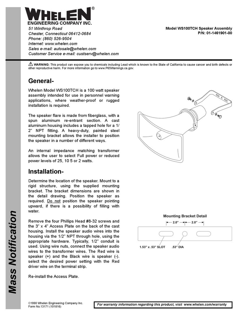
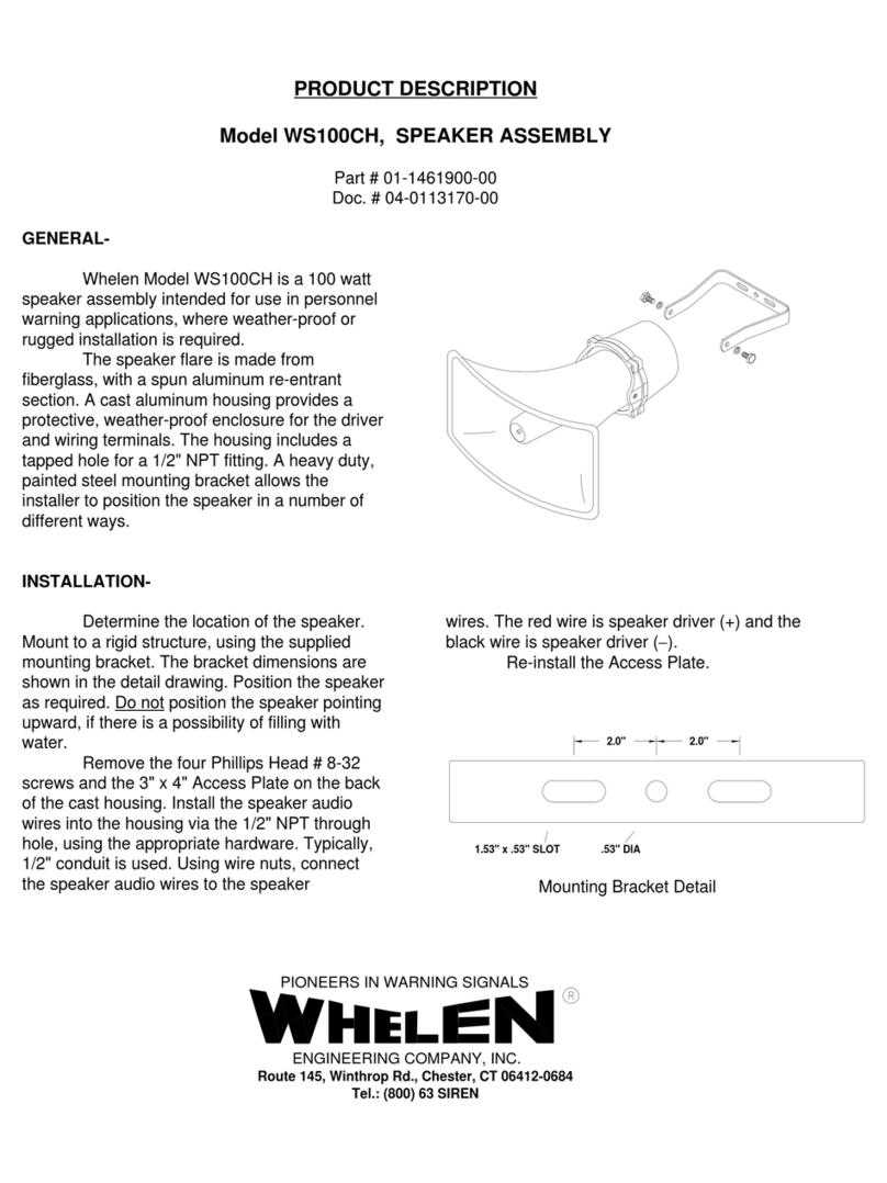
Whelen Engineering Company WS100CH Technical specifications

Whelen Engineering Company

Whelen Engineering Company WS100CH Technical specifications

Whelen Engineering Company WSXPL6T Series User manual

Whelen Engineering Company

Whelen Engineering Company WSXPL6T Series User manual

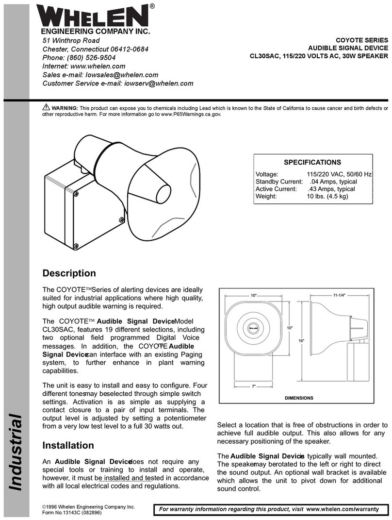
Whelen Engineering Company COYOTE Series User manual
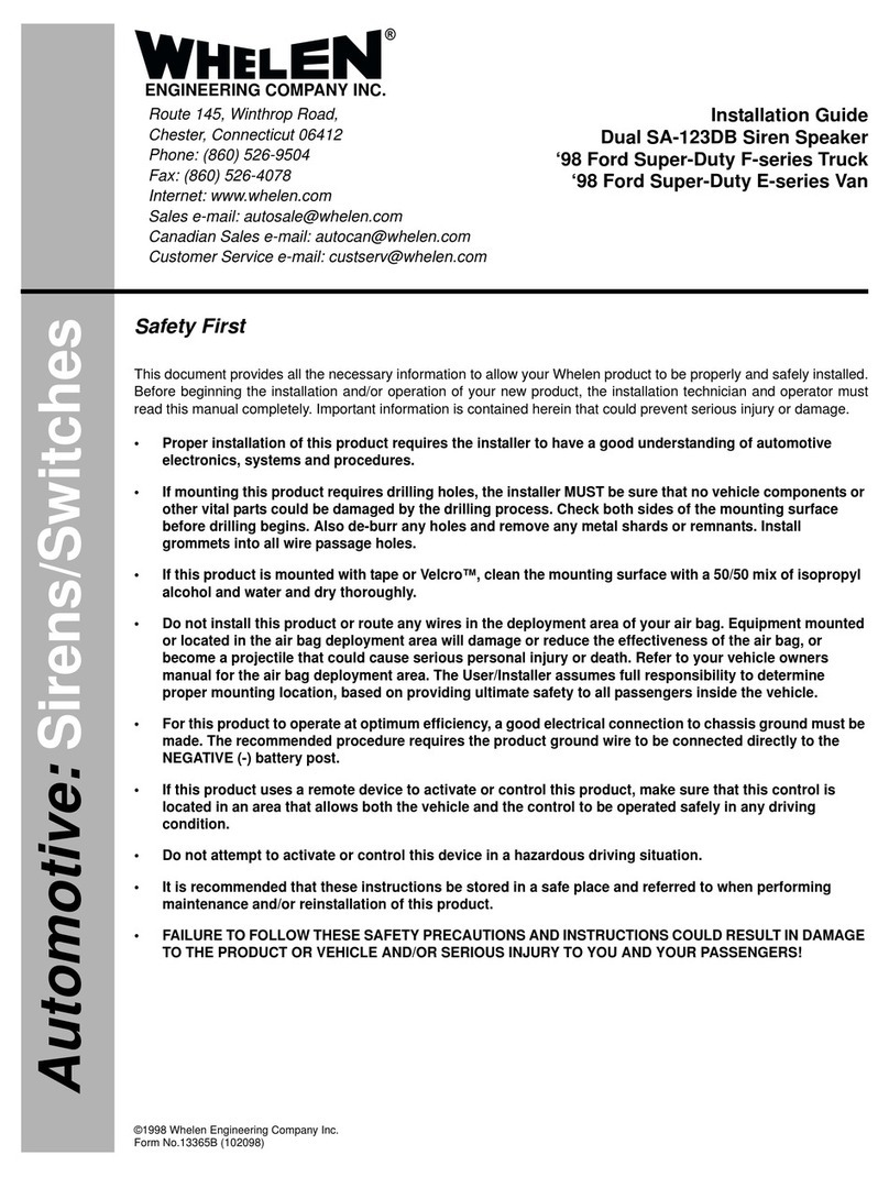
Whelen Engineering Company

Whelen Engineering Company COYOTE Series User manual

Whelen Engineering Company WS100TCH User manual

Whelen Engineering Company

Whelen Engineering Company WS100TCH User manual

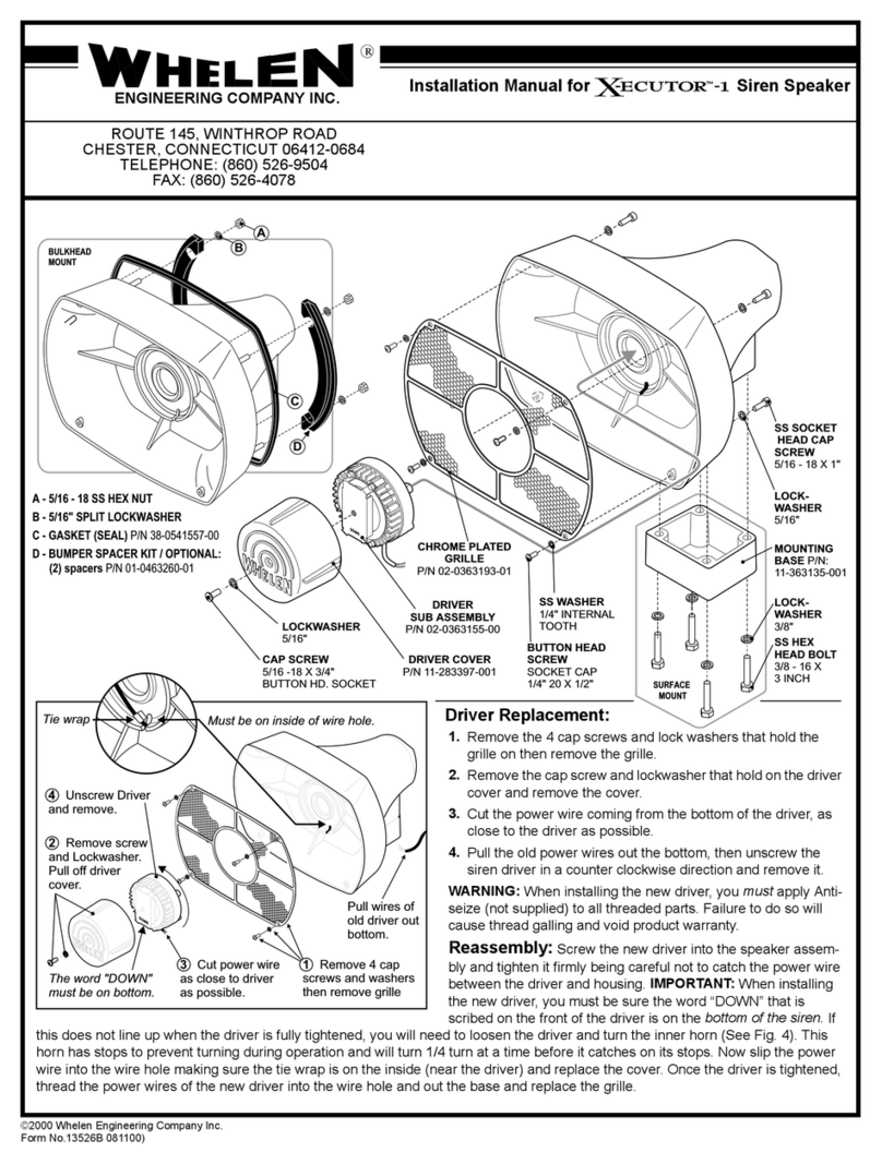
Whelen Engineering Company X-ECUTOR -1 User manual

Whelen Engineering Company

Whelen Engineering Company X-ECUTOR -1 User manual

Whelen Engineering Company WSXPL60 Series Technical specifications
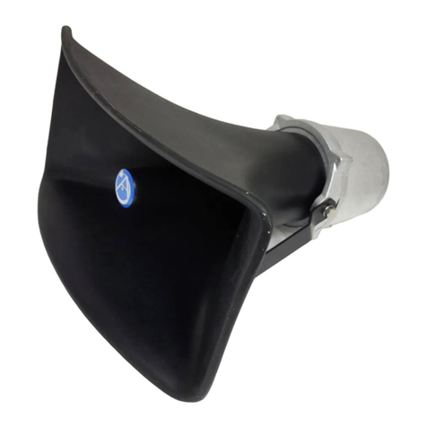
Whelen Engineering Company

Whelen Engineering Company WSXPL60 Series Technical specifications

Whelen Engineering Company WS60T User manual

Whelen Engineering Company

Whelen Engineering Company WS60T User manual

Whelen Engineering Company WSSC30 User manual

Whelen Engineering Company

Whelen Engineering Company WSSC30 User manual

Whelen Engineering Company WS100TCH User manual
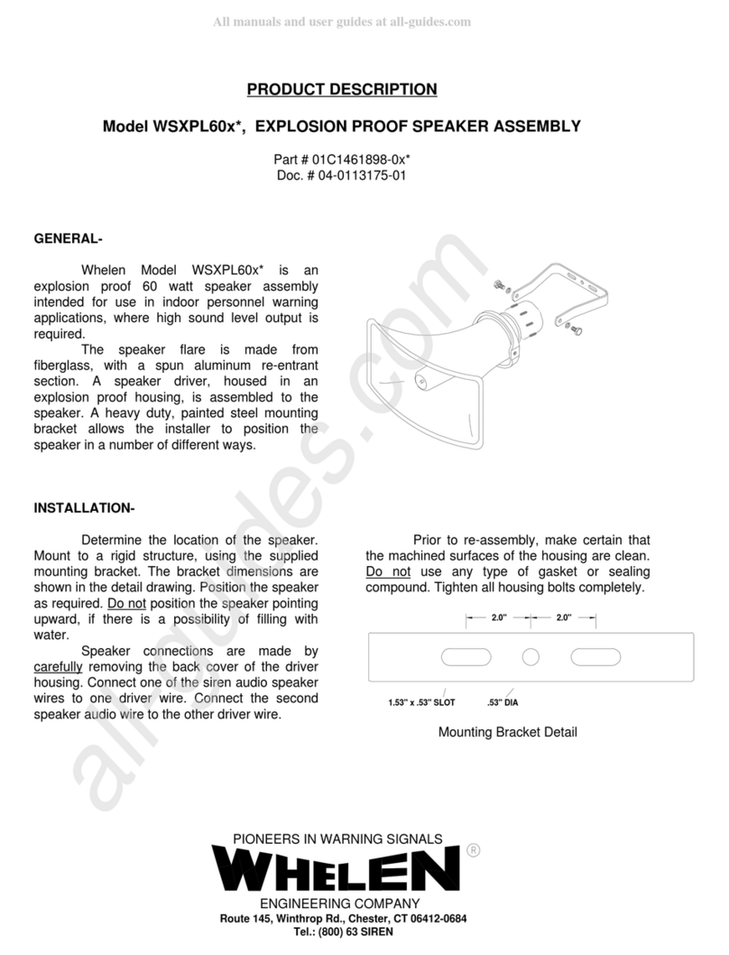
Whelen Engineering Company

Whelen Engineering Company WS100TCH User manual

Whelen Engineering Company SA122DB User manual

Whelen Engineering Company

Whelen Engineering Company SA122DB User manual

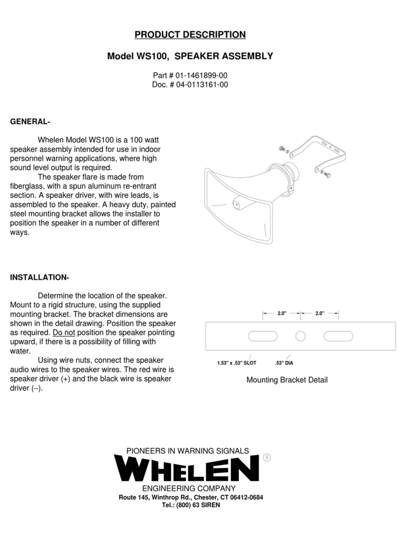
Whelen Engineering Company WS100 Technical specifications

Whelen Engineering Company

Whelen Engineering Company WS100 Technical specifications

Whelen Engineering Company Lo-Pro SA40 User manual

Whelen Engineering Company

Whelen Engineering Company Lo-Pro SA40 User manual

Whelen Engineering Company WPS-4000 Series User manual

Whelen Engineering Company

Whelen Engineering Company WPS-4000 Series User manual

Whelen Engineering Company WSXPL60 Series User manual
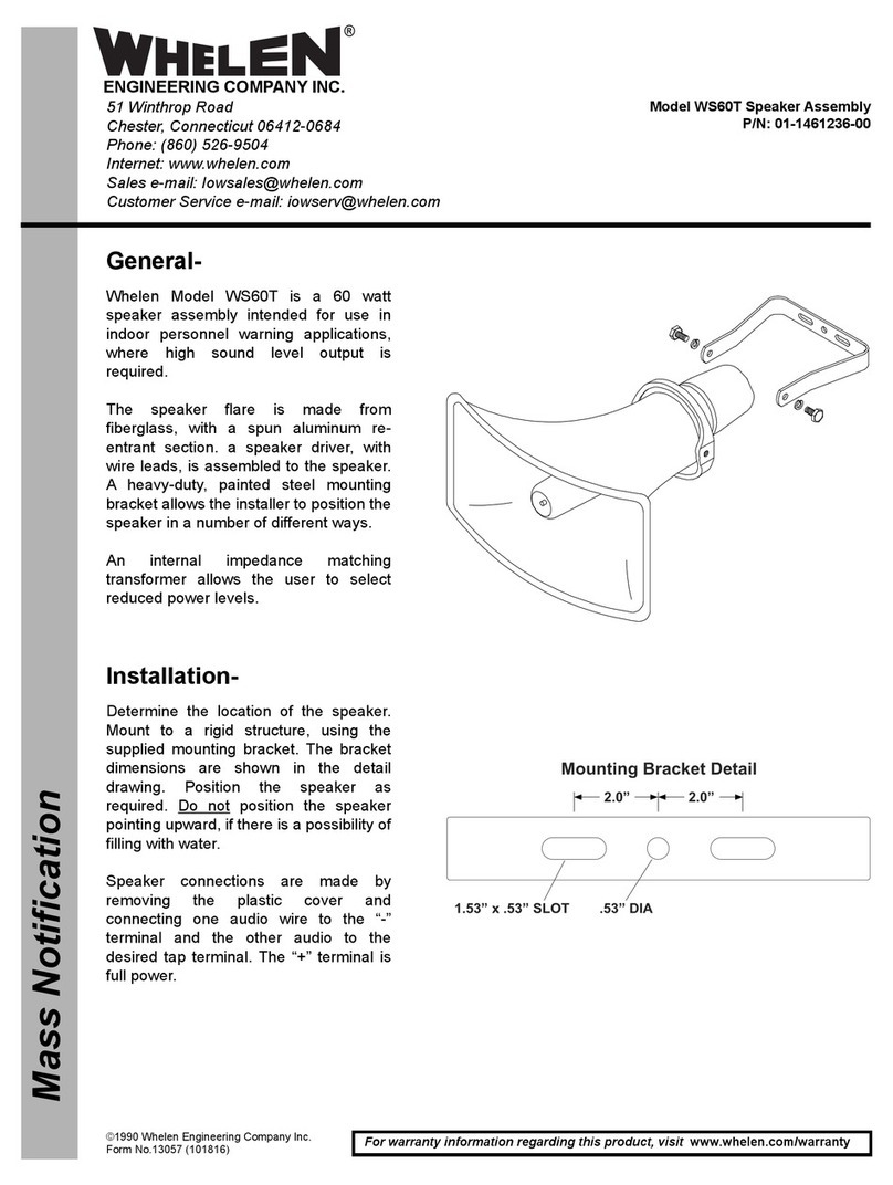
Whelen Engineering Company

Whelen Engineering Company WSXPL60 Series User manual

Whelen Engineering Company SA350MH User manual
Whelen Engineering Company

Whelen Engineering Company SA350MH User manual

Popular Speakers manuals by other brands

Harman JBL HORIZON 2 quick start guide

Harman

Harman JBL HORIZON 2 quick start guide

Fbt PSR 212 Specifications

Fbt

Fbt PSR 212 Specifications

JBL L65 instruction manual

JBL

JBL L65 instruction manual

Velocity ZT-SSPKCLP manual

Velocity

Velocity ZT-SSPKCLP manual

Niceboy BOOGIE manual

Niceboy

Niceboy BOOGIE manual

Audio Pro Evo Series Evo 20 Specifications

Audio Pro

Audio Pro Evo Series Evo 20 Specifications

JBL LSR2300 Series owner's manual

JBL

JBL LSR2300 Series owner's manual

DeWalt DCR009 Original instructions

DeWalt

DeWalt DCR009 Original instructions

Sennheiser Audiobeam Instructions for use

Sennheiser

Sennheiser Audiobeam Instructions for use

Pure Acoustics Proxima 60 owner's manual

Pure Acoustics

Pure Acoustics Proxima 60 owner's manual

Apogee Loudspeaker ALA-3 Product dimensions

Apogee

Apogee Loudspeaker ALA-3 Product dimensions

Sound Tube SM500i technical information

Sound Tube

Sound Tube SM500i technical information

Q Acoustics Concept 500 owner's manual

Q Acoustics

Q Acoustics Concept 500 owner's manual

dB Technologies LVX 10 user manual

dB Technologies

dB Technologies LVX 10 user manual

dB Technologies IS26T user manual

dB Technologies

dB Technologies IS26T user manual

Phase Technologies CI-10 VIII install guide

Phase Technologies

Phase Technologies CI-10 VIII install guide

Sound Tube LA880i installation instructions

Sound Tube

Sound Tube LA880i installation instructions

d & b audiotechnik SL Series manual

d & b audiotechnik

d & b audiotechnik SL Series manual

manuals.online logo
manuals.online logoBrands
  • About & Mission
  • Contact us
  • Privacy Policy
  • Terms and Conditions

Copyright 2025 Manuals.Online. All Rights Reserved.