6
Model 8500 Instruction Manual
Articulator Adjustments
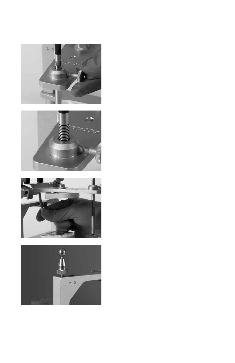
Protrusive Condylar Inclination: the angle of
the fossa in relation to the occlusal plane.
The inclination of the protrusive condylar path
can be adjusted by loosening the large black
clamp knob. The protrusive condylar path
inclination scale is on the side of the upper
member and is calibrated in increments of 5
degrees. The protrusive adjustment range is
0 – 70 degrees.
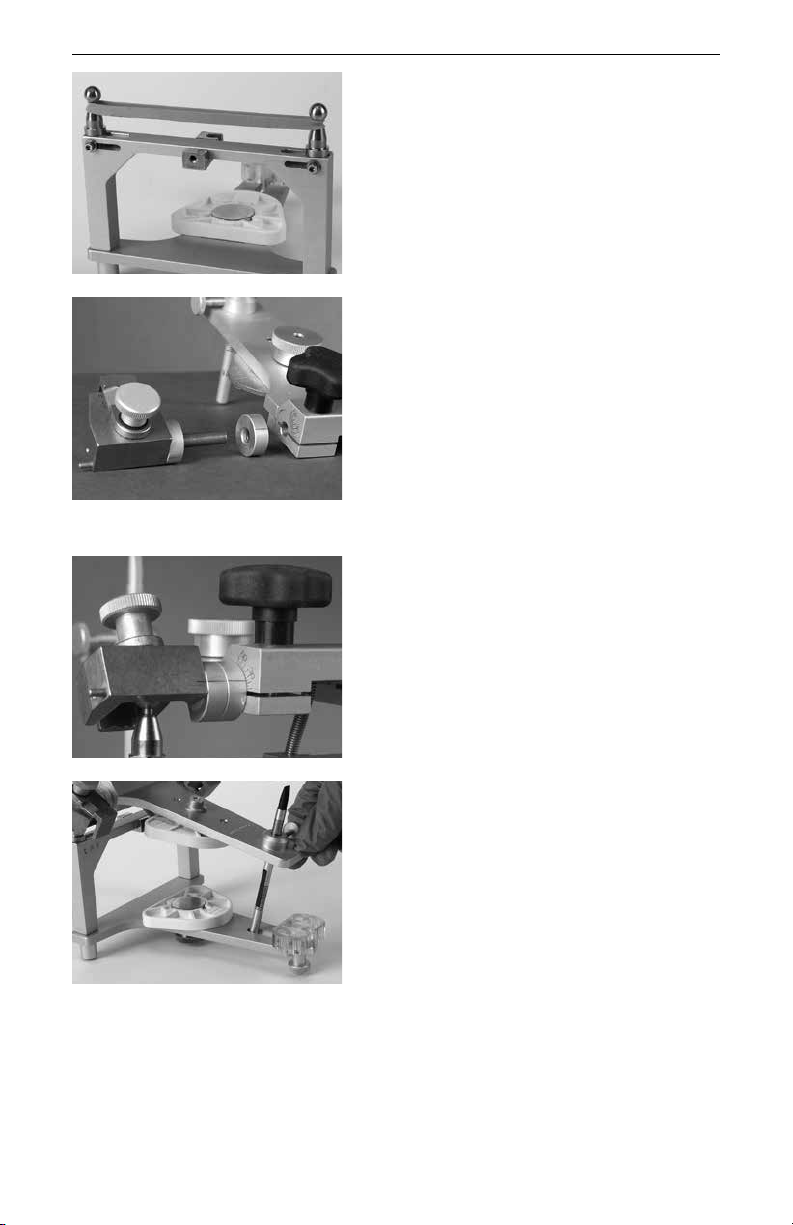
Progressive Side Shift: the path the orbiting
condyle follows on the medial wall of the fossa
as it orbits around the rotating condyle.
To set the progressive side shift, loosen the
side shift guide locking knob and move the
side shift guide until it touches the side of the
condyle element. The scale for the progressive
side shift adjustment is located on top of the
condylar guide and is calibrated in 5 degree
increments. The progressive side shift range is
0 – 40 degrees.
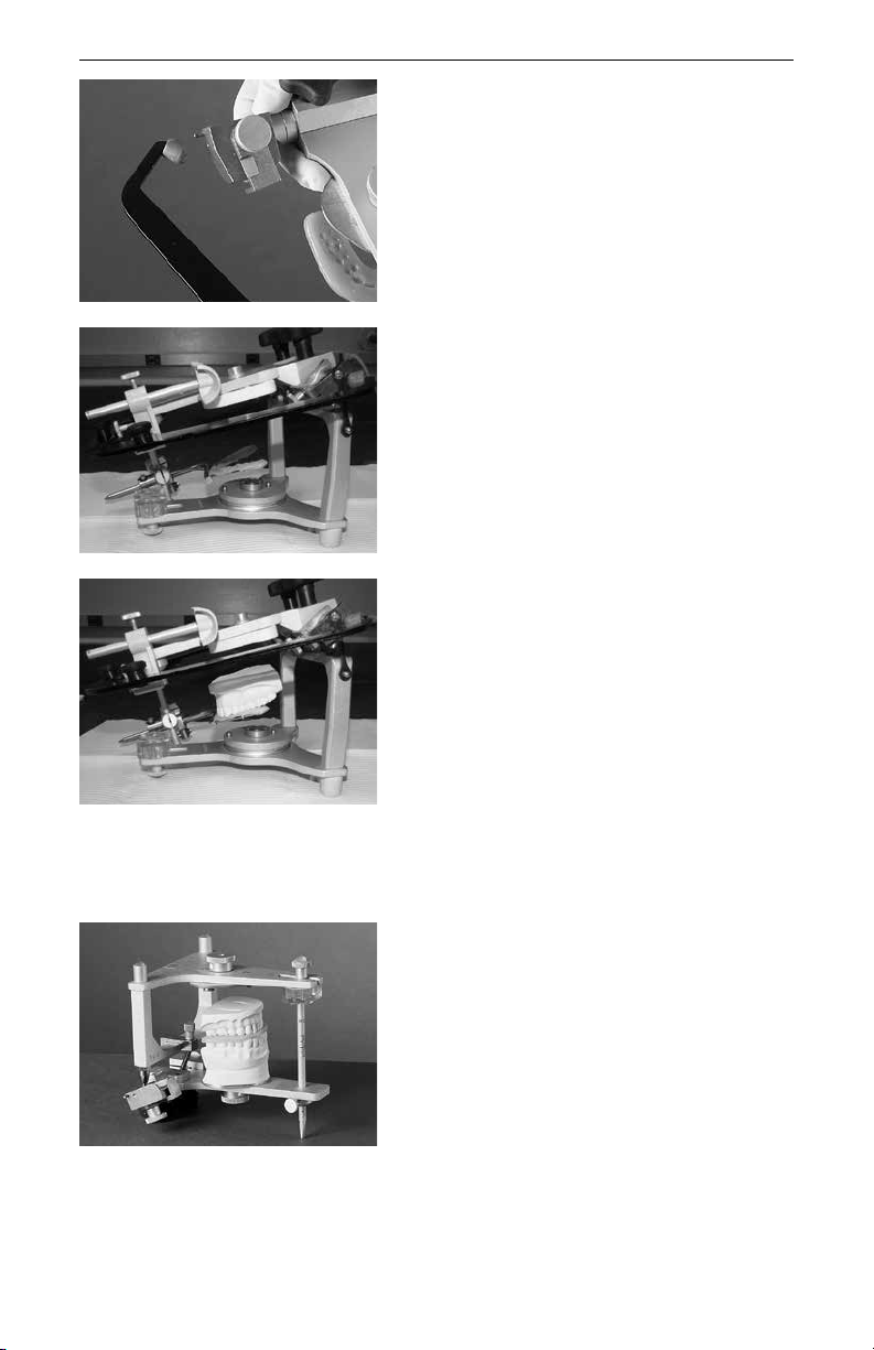
Direct Mounting the
Maxillary Cast
Remove or sufficiently raise the incisal guide
pin so the upper member of the articulator will
be able to rest on the horizontal crossbar of
the facebow.
Note: Set each condylar guide to 30 degrees
on the condylar inclination scale in preparation
for attaching the facebow assembly to the
upper frame of the articulator.
Mounting Casts on the 8500 Series
Articulators
In addition to a facebow record, the only records needed for complete programming
of the 8500 series are:
• Lateral bite records
• Protrusive bite record