®Gas D ye
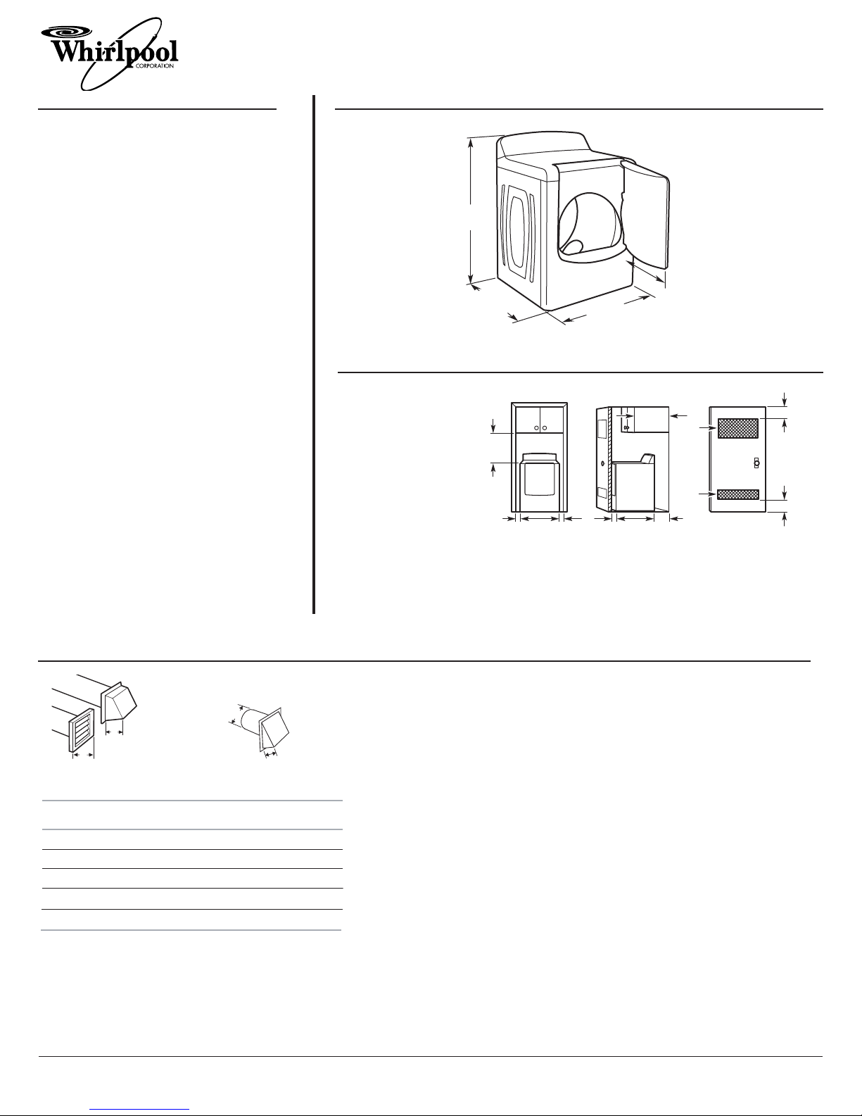
PRODUCT MODEL NUMBERS OVERALL DIMENSIONS
RECESSED AREA AND CLOSET INSTALLATION
EXHAUST VENTING
Because Whirlpool Corporation policy includes a continuous commitment to improve
our products, we reserve the ri ht to chan e materials and specifications without notice.
Dimensions are for plannin purposes only. For complete details, see Installation
Instructions packed with product. Specifications subject to chan e without notice.
Ref. W10164752B
07/2009
4"
(102 mm)
Louvered style Angled style
4"
(102 mm)
4"
(102 mm)
Boxhood style
21/2"
(64 mm)
A. Recessed area
B. Side view - closet or confined area
C. Closet door with vents
For closet installation
with a door, minimum
ventilation openin s in
the top and bottom of
the door are required.
Louvered doors with
equivalent air openin s
are acceptable.
1. Select the route that will provide the strai htest and most direct path outdoors. Plan
the installation to use the fewest number of elbows and turns. When usin elbows or
makin turns, allow as much room as possible. Bend vent radually to avoid kinkin .
Avoid 90° turns.
2. Determine vent len th.
The maximum len th of the exhaust system depends upon:
• The type of vent (ri id metal or flexible metal).
• The number of elbows used.
• Type of hood.
See the exhaust vent len th chart that matches your hood type for the maximum vent
len ths you can use.
3. Determine the number of elbows you will need.
IMPORTANT: Do not use vent runs lon er than specified in the Vent Len th Chart.
Number of
90 turns
or elbows
Type of
vent
Box or
Louvered
hoods
Angled
hoods
0Rigid metal 64 ft (20 m) 58 ft (17.7 m)
154 ft (16.5 m) 48 ft (14.6 m)
244 ft (13.4 m) 38 ft (11.6 m)
335 ft (10.7 m) 29 ft (8.8 m)
427 ft (8.2 m) 21 ft (6.4 m)
Rigid metal
Rigid metal
Rigid metal
Rigid metal
o
Gas supply: This dryer is equipped for use with
natural as. It is desi ned-certified by CSA
International for L.P. (propane or butane) ases
with appropriate conversion. When ri id pipe is
used it should be 1/2" IPS. When acceptable to the
as supplier and local codes, 3/8" approved tubin
may be used for len ths under 20 ft. (6.1 m). For
len ths over 20 ft. (6.1 m), lar er tubin should be
used. Pipe-joint compounds resistant to the action
of L.P. as must be used. If local codes permit, it is
recommended that new flexible metal tubin ,
desi n-certified by CSA, be used for connectin the
appliance to the ri id as supply line. (The as pipe
which extends throu h the lower rear of the
appliance has 3/8" male pipe thread.) An individual
manual shutoff valve must be installed within 6 ft.
(1.8 m) of the dryer in accordance with the
National Fuel Gas Code ANSI Z223.1.
Elect ical: A four-wire or three-wire, sin le
phase, 120-volt, 60 Hz, AC-only, electrical supply
is required on a separate 15 or 20 amp circuit,
fused on both sides of the line. A time-delay fuse
or circuit breaker is recommended.
Exhaust venting: Exhaust your dryer to the
outside. 4" (102 mm) diameter vent is required.
Ri id or flexible metal exhaust vent must be used.
Do Not use plastic or metal foil vent. Exhaust outlet
hood must be at least 12" (305 mm) from the
round or any object that may be in the path of the
exhaust.
29"
(737 mm)
221/4"
(565 mm)
291/4"
(743 mm)
431/2"
(1105 mm)
WGD6600V, WGD6600W
14" max.*
(356 mm)
ABC
29"
(737 mm)
5"
(127 mm)
1"
(25 mm)
1"
(25 mm)
18"*
(457 mm)
3"*
(76 mm)
3"*
(76 mm)
291/4"
(743 mm)
48" 2*
(310 cm2)
24" 2*
(155 cm2)


