J
n
Make sure that lower edges of the
cabinet, plus the back and bottom sides of the
dryer are free of obstructions to permit
adequate clearance of air openings for
combustion air. See “Recessed and closet
installation instructions”, on the back cover, for
minimum spacing requirements.
K
w For ease of installation, operating and
servicing (if ever needed) adequate space
should be provided around the dryer.
L
w An 1/&inch NPT plugged tapping,
accessible for test gauge connection, must be
installed immediately upstream of the gas
supply connector to the dryer.
The dryer and its individual shutoff valve must
be disconnected from the gas supply piping
system during any pressure testing of that
system at test pressures in exces of l/2 psig
(3.45 kPa).
The dryer must be isolated from the gas supply
piplng system by closing its individual manual
shutoff valve durlng any pressure testing of the
gas supply piping system at test pressures equal
to or less than l/2 psig (3.45 kPa).
Electrical
requirements
It uslng exlstlng exhaust system, clean llnt from
entlre length ot exhaust system. Make sure
exhaust hood Is not plugged wlth Ilnt.
Replace plasttc exhaust duct wlth rlgld metal or
tlexlble metal duct.
se duct tape
to seal
IIjoints, exhaust air
flow
better
Four-Inch rlgld metal
pipe
is preferred. Plan
/cJ
god
installation to use the
fewest number of
elbows and turns.
Metal rlexlble duct
should be fully extended
and supported when the dryer is in final
position. DO NOT KINK OR CRUSH THE DUCT.
The metal flexible duct must be completely
open to allow adequate exhaust air to flow.
Allow as much room as possible when using
elbows or making runs. Bend duct gradually to
avold kinking. Remove excess flexible duct to
avoid sagging and kinklng that may result in
reduced air flow.
Electrlcal Shock Hazard
l
Electrlcal ground Is required on thls
appliance.
l
Do Not modify the power supply cord plug.
It It does not flt the outlet, have a proper
outlet Installed by a quaIltIed electrlclan.
l
Do Not have a tuse In the neutral or
groundlng clrcult. A tuse In the neutral or
groundlng clrcult could result In an
electrlcal shock.
l
Do Not use an extenslon cord wlth thls
appliance.
l
Check wlth a qualltled electrlclan It you are
In doubt as to whether the appliance Is
properly grounded.
Failure to tallow these lnstructlons could result
In serious Injury or death.
It codes permlt and a separate groundlng wire
Is used, It Is recommended that a qualltled
electrlclan determlne that the groundlng path Is
adequate.
A 120-volt, 6CWlz, AC-only, 15or 2Gampere
fused electrical supply is required. Time-delay
fuse or circuit breaker is recommended. It is
recommended that a separate circuit serving
only this appliance be provided.
The exhaust outlet
is
located at the
bottom rear of the
dryer.
The exhaust duct
can be routed up, down, left,
right or straight out of the back of the dryer.
General space requlrements can be found in
“Recessed and closet installation instructions”
on the back cover. Use the straightest path you
can, where possible, to avoid 90” turns.
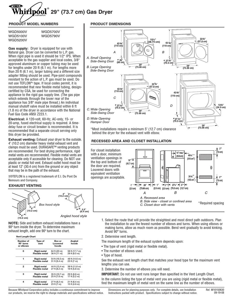
The maxlmum length
of the exhaust system
depends upon the type of duct used, number
of elbows and type of exhaust hood. The
maximum length for both rigid and flexible duct
is shown in chart.
n
If service is required, determine the
type of front panel your dryer has and follow
those instructions.
Recommended
grounding method
Electrlcal Shock Hazard
Disconnect tram electrlcal supply betore
removlng access panel.
Do not operate dryer wlthout access panel
securely In place.
Failure to kllow these lnstructlons could
result In electrlcal shock or death.
For your personal safety, this appliance must be
grounded. This appliance is equipped with a
power supply cord having a 3-prong grounding
plug. To minimize possible shock hazard, the
cord must be plugged into a mating 3-prong
grounding-type wall receptacle, grounded in
accordance with the National Electrical Code,
ANSI/NFPA 70 - latest edltlon’, and all local
codes and ordinances. If a mating wall
receptacle is not avallable, It is the personal
One-piece front panel
wiring diagram location
The dryer gas shutoff
valve is located
behind the one-piece
front panel.
responsibility and
obligation of the
customer to have a
properly grounded
3-prong wall
receptacle installed
by a qualified
electrician.
NUMBER
OF EXHAUST HOOD TYPE
90” TURNS A B C
0 64 FT. 64 FT. 58 Fr. MAXIMUM
1 54 FT. 54Fr. 48 FT. LENGTH OF
2 44 Fr. 44Fr 38 Fr. 4’ DIA. RIGIC
METAL
3 35 Fr. 35 Fr. 29Fr. DUCT.
4 27 Fr. 27 FT. 21 Fr.
0 36 FT. 36 FT. 28 FT. MAXIMUM
1 31 Fr. 31 FT. 23 FT. LENGTH OF
4’ DIA.
2 27 FT. 27 Fr. 19 FT. FLEXIBLE
61
The wiring diagram isThe wiring diagram is
1 located inside thelocated inside the
console.console.
These Items should beThese Items should be
accessed only by aaccessed only by a
. quallfled servicequallfled service
3 25 FT. 25 FT. 17 Fr. METAL
4 23 FT. 23Fr. 15 FT. DUCT.
The maximum length using a 2” x 6” rectan 9 ular duct
with 2 elbows and a 2-l/2 (TyPE C) exhaus hood is 8 ft.
power ‘/_
supply cord
Copies of the standards listed above may be-
obtained from:
l
National Fire Protection Association
Bafterymarch Park
Quincy, Massachusetts 02269
- technklan.
gas shuhl valve o\ne-piece
front panel
1.
Disconnect electrlcal supply.
2. Remove lint screen and set aside.
3. Remove two screws from lint screen area.
4. Grasp front cabinet top corners and pull
forward and up (top is hlnged at rear).
5. Remove two screws from front panel
flanges. Lift front panel off lower clips,
6. Remove door switch wires, if necessary,
and set front panel aside.
7. Reassemble in reverse order.
Note: The door switch wires must
not
touch
the drum.
Lower access panel
wlrlng diagram location
1,
Disconnect
electrlcal supply.
2. Insert flat-blade
screwdriver between
cabinet front and
lower access panel
3-inches in from
each side. Push
down on retalner
clips and pull lower
access panel
forward. The lower
access panel is
hinged at the
bottom.
access
3.
Close lower access
-..-.-..
valve
panel
panel.
Gas shutoff valve “open” and
“closed” position
Optional shutoff
valve /FL
Exhaust
requirements
For exhaust systems
not covered by the
exhaust length chart, see Service Manual, Part
No. 603197 available from your local parts
distributor.
Servlce check:
The back pressure in any
exhaust system used must not exceed 0.6
inches of water column measured with an
inclined manometer at the point that the
exhaust duct connects the dryer.
An exhaust hood
should cap the
exhaust duct to prevent exhausted
air from returning into dryer. The
outlet of the hood must be at least
12 inches from the ground or
anything else that may be in the
path of the exhaust. %
12” min.
Four-Inch outlet hood Is preterred.
However, a
2-l /2 inch outlet may be used with short
systems only. A 2-l /2 inch outlet can result in
longer drying times than other hood types.
For
permanent Installation, a statlonary exhaust
system Is required.
Mobile home installation
Thls appliance Is sultable for moblle home
Installations. The lnstallatlon ot the dryer must
conform to the Manutactured Home
Constructton and Safety Standard, Title 24 CFR,
Part 3280 (formerly the Federal Standard tar
Moblle Home Constructlon and Satety, Title 24,
HUD, Part 280, latest edltlon).
For all installations, this appliance MUST be
fastened to the wall with cable bracket and
MUST be exhausted to the outside.
The dryer must have an outside
exhaust. If the dryer is exhausted
through the floor and the area
under the mobile home is
enclosed, the exhaust system
must
terminate outside the
enclosed area. Extension
beyond the enclosure will
prevent lint and moisture
buildup under the mobile home.
Fire/Health Hazard
l
Do Not use non-metal, tlexlble duct.
l
Do Not use metal duct smaller than tour
Inches In diameter.
l
Do Not Use exhaust hoods wlth magnetic
latches.
l
Check that exhaust system Is not longer
than specltled. Exhaust systems longer
than speclfled wIII:
- Accumulate Ilnt.
- Shorten the llte ot the dryer.
- Reduce perlormance, resulting In
longer drying times and Increased
energy usage.
Failure to follow speclrlcatlons may result In a
flre.
l
Do Not exhaust dryer Into a chimney,
furnace cold alr duct, attlc or crawl space,
or any other duct used tar venting.
l
Clean the exhaust system every other year.
. Do Not Install tlexlble duct In enclosed
walls, celllngs or tloors.
Accumulated llnt could be tuel for a flre or
cause molsture damage.
Exhaust the dryer outslde to prevent
exposure to substances In the gas fuels and
combustion which may be harmtul to your
lealth.
he molsture and lint Indoors may cause:
- Lint to gather lnslde and around the
dryer and be a tuel for tlre.
- Molsture damage to woodwork,
turnlture, palnt, wallpaper, carpet, etc.
- Housecleanlng problems and possible
health problems.
:allure to tallow these lnstructlons could result
n
Hre damage, property damage, personal
nJury or health problems.
posItIon
gas shutoff va’lve i;
open or “on” position
Panel B
