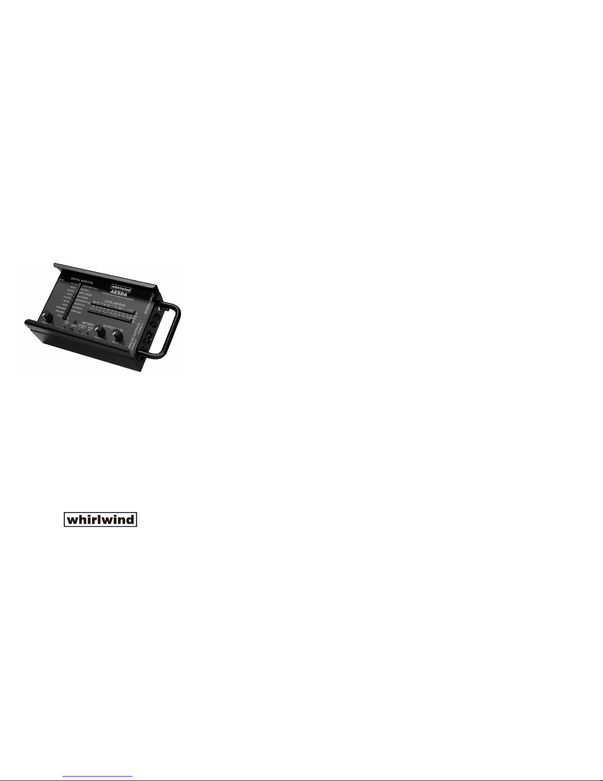
The WhirlwindAESDAis a portable device for convertingAES-3 and
S/PDIF digital audio signals into analog audio signals. Digital input to
theAESDAisthroughthefemaleXLRorBNC.There are level meters
that display the level of the incoming digital signal or they can be
switched to display the analog output signal level. Each of the two
decodedanalogaudio outputs has an independent level control, from
which the signal is sent to the analog metering circuits and male XLR
outputs. Another unbalanced analog output is provided on a 3.5 mm
TRS jack, with its own level control, for use with headphones or as an
unbalanced line level driver. Both professional and consumer
versionsofAES-3canbedecodedbytheAESDA.
Additionally, theAESDA provides diagnostic analysis of the incoming
AES-3 and S/PDIF digital signals for help in troubleshooting signal
faults. The digital monitor section identifies the sample rate and
characteristics of the incoming digital signal, and if there is a problem
in the digital audio stream several different fault types can be
identified.
Theory of Operation
TheAESDAwasdesigned to provideaportablemeans of convertinganAES-3 or S/PDIF
digitalaudiostreamintoaprofessional high-qualitytwo-channelanalogaudiooutput. The
digital input is extensively screened at receiving, with faults in the data or transport
annunciatedbytype. Adual 11-segmentVU metermonitors theaudio level fromthe DAC
or the level at the output. In the interest of conserving battery power, two display modes
are available on the VU meter. One is a bar graph of the signal level, the other is a single
LED which indicates the peak instantaneous signal level, with the single LED consuming
less power than the bar graph. A ten-segment red LED bar serves to indicate the various
operating modes and detected faults, if any. A switch selects the function of this LED bar,
either to indicate operating mode, detected sample rate, etc., or to display any detected
fault. The analog output has separate level controls for the left (A) and right (B) side.
Output level may be set by selecting the analog output on the VU meters, and setting the
controlstothedesiredvalue. Aheadphonemonitorjack withseparate levelcontrolisalso
provided for checking the analog audio signal. Recommended headphone impedance is
between16and100Ohms. Thisjackcanalsobe usedasanunbalancedlineleveloutput.
Primary power for the unit can be sourced from four “AA” cells (Alkaline, Lithium-Ion or
Nickel-Metal-Hydride cells are recommended). An external coaxial power jack (5.5mm x
2.1mm) is provided for situations where battery power may not provide an adequate
length of operation. The external power source should be able to provide 12 Watts of
powerataVoltagerange from3.5VDCto15VDC. This allows theAESDAtooperate on a
widevarietyofpowersourcesincludingcarbatteries,portablecamerabatteries,or a“wall
wart”typeofpowersupply.
Digital Monitor LED Function Details
Digital Info Indicators
SampleRate
There are six sample rate indicators that show the closest standard sample rate to
the signal as received: 44.1kHz, 48kHz, 88.2kHz, 96kHz, 176.4kHz, and 192kHz.
Signals that have sample rates lower than 44.1kHz may be locked to and decoded
by the AESDA, but their sample rate will not be displayed. Only one sample rate
LEDshouldbeilluminated at onetime in normaloperation. Withnoinputsignal, the
FaultLEDandtheNoLockLED(inFaultTypemode)willbeilluminatedinstead.
Audio
The Audio LED indicator illuminates when the input digital data stream has been
determined to be Pulse-Code Modulated (or PCM) digital audio. For other digital
inputs that are not PCM audio, such as TDM data to DTS-CD, this indicator will be
off.
Consumer
The Consumer LED indicator illuminates when the Pro/Consumer mode bit in the
digitalaudiostream'sStatusbitindicatesConsumermode,andisoffinProfessional
mode. Note that this indicator only presents validly when the AESDAis locked to a
validPCMaudiodatastream.
Pre-Emph(asis)
The Pre-Emph(asis) LED Indicator illuminates when the digital audio stream's
Status bit field for this condition indicates that it is present. Typically, pre-emphasis
is only used for sample rates of 32kHz, 44.1kHz, and 48kHz. When the indicator is
off, it indicates that the audio signal embedded in the digital stream has not been
pre-emphasized.
Fault
The Fault LED indicator illuminates when a detected fault, either in the hardware or
thedigital inputsignalhas beendetected. Theuserthen canswitchthe unit overto
theFaultTypedisplaytofurtheridentifythefault.
Fault Type indicators
HardwareFault
The Hardware Fault LED Indicator is illuminated if anything in the power-on
diagnostic tests did not pass, or if the information presented by the control switches
is invalid or cannot be interpreted. The unit may not operate properly with this LED
illuminated.
NoLock
The No Lock LED Indicator illuminates if no signal is present on either of the two
digital input connectors, or if the signal cannot be interpreted. Application of a valid
digitalaudiostreamtoeitherdigitalinputwillcausethisindicatortoextinguish.
ParityError
The Parity Error LED Indicator illuminates when the incoming data did not have an
evennumber of onesand zeros,orifthe number ofbitswasnot 32. Typically,parity
andbit-lengtherrorsareindicativeof weak or noisy signals. Parityandbiterrorsare
also typically not consistent between fields of data, so flickering of this LED is not
uncommoninthepresenceofthesetypesoferrors.
CRCError
The CRC Error LED Indicator illuminates when an AES Professional Data Block
Cyclical Redundancy Check did not pass. When generated, the data is passed
through a CRC generator, which calculates and embeds an 8-bit check word at the
endofeachframe. Thedigital receiver intheAESDArecalculatesthisCRC number
from the received data and compares its result to the CRC number received. If the
two do not match, then the data was not received the same way that it was
transmitted, i.e., there may be one or more data bits that are in error. Note that
Consumer ModeAES-3 and S/PDIF do not use CRC checking, so this LED will be
offwhen receivingaudiodataofthistype.
ConfidenceFlag
The Confidence Flag LED Indicator illuminates if excessive distortion is detected in
the digital signal received. The distortion may be from low signal level, excess or
incorrectcableimpedance,or asymmetryinthesignal(the“1”partand the“0”partof
the signal not of equal length within a specific percentage). If only this error exists,
without Parity, CRC, or No Lock errors, it is indicative of a signal that is marginally
useable,andprobablynotreliablein the longrun. Whenothersignal-typeerrorsare
present,this is indicativeofabad cable, toolongofa cable run,a badtransmitter,or
anexcessivelynoisyenvironment.
ValidityBit
TheValidityBitLED IndicatorilluminateswhentheLeftorRightorbothofthe Validity
Bits indicate invalid data. These bits are embedded in the audio data, and there is
one validity bit in each subframe. When one channel is invalid, the Validity Bit LED
willflicker;ifbothchannelsindicateinvalid,theLEDwill besteadilyon.
NoError
The No Error LED Indicator is illuminated when no detected error is present. This
provisionallowsatleastoneLEDtobeilluminated when FaultTypemode isentered
andtherearenofaults.
OverTemp
TheOverTempLED Indicator illuminatesifthe detected temperatureinsidethe unit
exceeds 85°C. This temperature is the upper limit for reliable operation of the
various internal components, and if exceeded for a long period of time, could cause
permanentdamagetotheAESDA. NoshutdownactionisinstigatedbytheAESDA,
itjustservesasawarningtotheuser.
AESDA
PORTABLE AES TO ANALOG CONVERTER
Warranty
This product is guaranteed for one year from the date of purchase against manufacturing defects. For warranty service, return the
unit, along with the original sales receipt, to: whirlwind, 99 Ling Road, Rochester, NY 14612, postage prepaid. We will repair or
replacetheunitatouroptionandpaythereturnpostage.
99 Ling Road . Rochester, NY 14612
Phone 585 663-8820 . Fax 585 865-8930
http://www.whirlwindusa.com