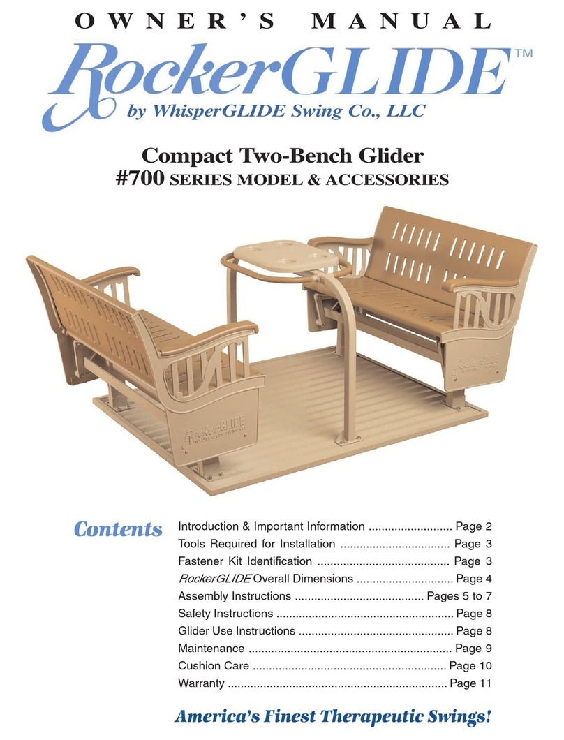
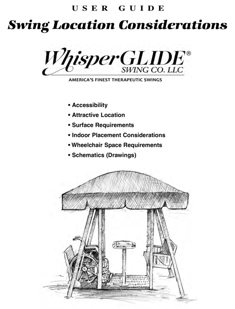
WhisperGLIDE Wheelchair Accessible Swing User manual

AMERICAÕS FINEST THERAPEUTIC SWINGS
OWNER’S MANUAL
Introduction & Important Information .......................... Page 2
Swing Specifications & Parts Identification ................. Page 3
Canopies, Cushions & Lap Bar ................................... Page 4
Site Selection Requirements ..................................... Page 5
Tools Required for Installation .................................. Page 5
Fastener Kit Identification ......................................... Page 6
Assembly Instructions ............................................ Page 7-14
Safety Instructions ..................................................... Page 15
Maintenance ....................................................... Page 16-17
Warranty ................................................................... Page 18
Contents
America’s Finest Therapeutic Swings!
Wheelchair Accessible Swing
#601 SERIES MODEL & ACCESSORIES

Use Inside or Outside
Introduction & Important Information
Thank you for purchasing a
Whisper
GLIDE®Swing!!
This manual covers specifications, installation, use,
and maintenance for the following:
•Model 601 wheelchair-accessible
Whisper
GLIDE®Swing
•
Whisper
GLIDE®Canopies
•
Whisper
GLIDE®Cushions
•
Whisper
GLIDE®Lap Bars
Read this manual to learn how to properly assemble
and care for your
Whisper
GLIDE®Swing.
Failure to do so could result in personal injury or
equipment damage.
Do not throw away this manual.
Keep in a safe location for future reference.
All information, illustrations and specifications in this
manual are based on the latest information available at
the time of publication. The right is reserved to make
changes at anytime without notice.
For information regarding
Whisper
GLIDE®Swings
and accessories, contact:
WhisperGLIDE®Swing Company, LLC
Tel. 1-800-944-7737
Fax 1-715-457-0048
www.whisperglide.com
PA G E T W O
Intended Use of WhisperGLIDE®Swings:
The
Whisper
GLIDE®Swing is designed with user safety
in mind. However, as with all mechanical equipment,
there are potential hazards which could result in injury
to persons, and/or structural damage to the equipment,
if the swing is improperly used or improperly supervised.
The
Whisper
GLIDE®Swing is designed for gentle
back-and-forth swinging motion. It is NOT intended for
rigorous aerobic or cardiovascular exercise.
USE ONLY UNDER ADULT OR CAREGIVER
SUPERVISION TRAINED IN THE USE OF THE SWING.
Whisper
GLIDE®Swings are NOT public playground
equipment. The swings are outside the scope of the
U.S. Consumer Product Safety Commission’s (CPSC)
definition of “public” playground equipment and outside
the scope of the American Society of Testing and
Materials (ASTM) Standard Consumer Safety
Performance Specification for Playground Equipment
for Public Use.
Toreduce the potential for misuse of the
Whisper
GLIDE®Swing as children’splayequipment,
and the potential for any related injuries,
DO NOT install the
Whisper
GLIDE®Swing in or near
child play areas where unsupervised access exists.
If the swing is transferred to another owner,notify
Whisper
GLIDE at 1-800-944-7737 and makethe
transferee aware of the above information.
P.O. Box 188, Mosinee, WI 54455
FAX:
1-715-457-0048 •
www.whisperglide.com
©April 2018, WhisperGLIDE Swing Co.
For Additional Information
Check us out on our Website, or call us!
1-800-944-7737
Experience the Feeling!
AMERICAÕS FINEST THERAPEUTIC SWINGS

PRIMARY COMPONENTS
The WhisperGLIDE Wheelchair Accessible Swing – Model 600 Materials
Frame (legs, hangers, upper assembly); push-pull bar; safety handrail; seat castings Aluminum
Support & pivot shafts; lock-up shafts; fasteners (nuts, bolts, screws) Stainless steel
Platform; seat & seat back; wheelchair platform, ramp (wheelchair models) Vinyl coated steel
Crank handle/gearboxassembly (for wheelchair model ramp/platform) Aluminum, stainless steel, bronze
Table Fiberglass
Powder-coat paint finish Polyester Urethane
The 600 Series Adjustable Wheelchair Accessible Swing
Therapeutic Handle
(Wheelchair Side Only)
Vinylclad
Bench Seat
Canopy
Safety Floor Handrail
Stop Bar Vinylclad Swing Floor
Vinylclad
Wheelchair
Ramp
Lock-Up Receptacle
Hangers
Gear
Assembly
Powdercoated
industrial
aluminum frame
Table Hand-Bar
(Push-Pull Bar)
Leg(s)
NOTE: The Table Bar / Push-Pull Bar was replaced by the Table Bar / HandRail beginning Year 2015.
See Assembly Instructions Step 4-A: Two Bench Platform Assembly.
PAGE THREE

PAGE FOUR
Canopies & Cushions
WhisperGLIDE Primary Fabric Components Material Comment
WhisperGLIDE Series 600 Fabric –Coffee Linen, Cypress Vinyl-coated polyester Flammability rating
Woods, EarthBright, Fern Dance, Mocha Thyme, Sea Breeze, CS-191-53/CA 117E
Sierra Mountain, Terra Sienna, Windsor Trellis, Woodland Green
WhisperGLIDE Series 600 Fabric –SaharaBeauty Vinyl-coated polyester Flammability rating
CS-191-53/CA 117E
WhisperGLIDE Series 600 Fabric – Forest Green, Vinyl-coated olefin Flammability rating
Basketweave CA TB117-2013
Cushion fill Polyester fiber
Pictured is a sample canopy and cushion from the WhisperGLIDE®product line.
Lap Bar (optional)
Pictured here is a lap bar, intended for use on the bench seat only.
When not in use, the lap is stored between brackets on outside
of upper frame aboveand behind bench seat.
Component Material
WhisperGLIDE Series 600 –Lap Bar Aluminum
Powder-coat paint finish Polyester Urethane

One 1/2-in wrench
one 9/16-in wrench
one 3/4-in wrench
and a socket wrench or adjustable wrench
PAGE FIVE
Installation: Site Selection Requirements
Approximate swing dimensions Location
Height – 7-ft. 4-in. / Base – 7-ft. x 8-ft. Place swings in easily accessible and highly visible areas
Surface requirements –Alevel, flat, hard surface – cement, wood, brick or patio blocks
Space needed –Although when not in use
Whisper
GLIDE Swings require a minimum space of 7-ft x 8-ft,
additional space is needed for adequate and safe entry, use and exit. Space requirements also depend on location
of swing entry and exit, and your specific needs. If your swing is placed adjacent to walkways,
or access to all sides is not necessary, additional space requirements may be reduced.
Wheelchair Accessible Swing: Ideal – 13-ft X 18-ft
Two Bench Swing: Ideal – 13-ft X 14-ft
QUESTIONS? Please call us to discuss your specific situation and space options: 1-800-944-7737
Level
Tape Measure
Electric Drill
One Medium Size
#2 Phillips screwdriver
Tools Required for Installation
AND
Two 1/2-in wrenches
one 7/16-in wrench
two 9/16-in wrenches
two 3/4-in wrenches
OR two socket wrenches
NOTE: USE ONLY HAND WRENCHES
DO NOT USE ELECTRIC WRENCHES, OR AIR-POWERED WRENCHES FOR SWING ASSEMBLY.
OR

Fastener Kit Identification
The fastener kit contains labeled “subkits” for easy assembly of the swing.
Also, you can use the actual size fastener codes, identified below, for cross-reference.
A = Upper frame splice (8)
B=Legs to Upper frame (4)
E = Floor handrail to platform (8)
Seats to seat end castings:
Wheelchair swing (4)
(Note: Two Bench swing (8)
F=Seat stabilizer bar (8)
Seat to hangers: Wheelchair (4)
(Note: Two Bench (8)
H=Gear Assembly fasteners (4)
I = Ramp to platform(1)
K=Canopy end rail to upper frame (4)
L = Blue Tapcon screws (12)
Lockup receptacles (8)
Leg foot pad (4)
A2-1/4" x 3/8"
B3-1/4" x 3/8"
E1" x 1/4"
F2"x5/16"
H1-1/4" x 3/8"
K5/8" x 3/16"
L1-3/4" x 3/16"
I1-1/2" x 3/8"
PAGE SIX

Step One: Upper Frame Assembly
PAGE SEVEN
The frame is contained in two identical boxes. One is labeled “OPEN ME FIRST”.
Use hardware contained in the “Frame Assembly Kit” which is located in Box #2.
1. Place both sides of the upper frame upside down on the ground, deck, or patio where the swing
will be located.
2. Insert the two anodized rectangular 18" long sleeves from Box #2 into one side of the one upper
frame half so the holes in the sleeve line up with the holes in the frame. Open the fastener pack labeled
“Frame Assembly Kit”. Insert the 2-1/4" bolts (A) into each of the four holes from inside to outside the
frame so the nuts are on the outside.
3. Slide the second half of the upper frame over the 18" sleeves,
once again lining up the four holes. Insert the remaining four
2-1/4" bolts (A) and tighten all eight of the flange nuts firmly.

Step Two: Leg Assembly
The legs are contained in the longest box labeled Box #5.
There are two left legs and two right legs.
Use the hardware contained in the “Frame Assembly Kit” pack.
1. Note “Left” and “Right” labels on the legs and on the frame.
Position a leg into the appropriate corner; insert the 3-1/4" bolt (B) and tighten securely the flange nut.
The nuts should be on the outside of the frame. Repeat this on all four legs.
Note: If placing the swing indoors (with low ceiling clearance), insert and fasten two of the legs,
lift frame upright. Then insert and fasten the remaining legs.
2. LIFT FRAME and place right side up on the prepared site location.
Check, using a level, to be sure each section of the upper frame is level.
Note: DO NOT anchor the legs to the prepared surface at this point.
Anchoring is one of the final installation steps.
PAGE EIGHT

Step Three: Swing Hanger Installation
PAGE NINE
The swing hangers are contained in the second longest box and labeled
Box #4. They connect the upper frame to the platform of the swing. There
are two right hangers (these have lock-up shafts) and two left hangers
(these do not have lock-up shafts). All four hangers have either a “Left” or
“Right” removable labels. The “Right” Labels are on the hangers for the right
side of the swing if one is sitting either on the bench seat or the wheelchair.
Use the four bolts and nuts that are already attached to the hangers to
affix it to the upper frame.
1. Note the top and bottom of the hangers. The stainless steel shafts at the bottom
end of each hanger fits into the applicable bronze bushing on the swing platform.
2. The hanger with the lock-up shaft is placed on the right side (assuming you
are seated in the wheelchair). The two hangers on the wheelchair side are notably
different from the ones on the seat side, with each shaft having a washer and
anut plus the stainless steel shafts are longer. The two hangers also have
removable “Wheelchair side” labels. In Step Four, Wheelchair Platform
Assembly, these shafts will be inserted into the bronze bushing on the
platform and tightly secured by the washers and nuts.
3. The hanger with the lock-up shaft on the right side of the bench (as you are
seated on the bench) has a shorter shaft which slips into the bronze bushing
on the platform. Be certain the two hangers with lock-ups are diagonal
from each other.
Note: The “Wheelchair Directions” label
should be facing out, thus readable while
standing outside the swing.

Step Four: Wheelchair Platform Assembly
The wheelchair platform assembly consists of the platform and the ramp and are contained
in the boxes labeled Box #7, Box #8. Use hardware contained in 3 different sub-kit packets:
Seat, Stabilizer Bars & Handrail Kit; Table Handrail Kit; Wheelchair Ramp Kit.
The locknuts for the Table itself are already fastened to the imbedded bolts in the table.
Installing the platform and the floor handrail
requires two workers.
1. Floor handrail: Securely place a stable object/block under the end of the platform to create
enough space to install the floor handrail nuts. Insert the two bolts (E) through the top of the handrail
plate on one side of the handrail. Secure by tightening the nuts VERY TIGHT.
Repeat the procedure to install two fasteners on the opposite side of the platform.
2. Attach Hangers to Platform:
Lift one end of the platform and slide the shafts into the bronze bushings on the platform.
Repeat this step for all of the hangers. Sometimes a rubber hammer is needed to make the shafts slip
all the way into the bushings. TIGHTEN THE NUTS ONTO THE SHAFT VERY TIGHTLY.
3. Stabilizer Bar Installation: Note the location of holes on the hangers where the stabilizer bars
will be installed. On the wheelchair side of a swing, the bar is located near the top of the hangers.
(See drawing on page 11). On the bench side,the bar is located just abovethe swing platform.
Lift the upper stabilizer bar into place between the hangers. Put the four bolts (F) into place.
The nuts should be on the inside of the hanger. Repeat the same procedure for the lower stabilizer bar.
Do not securely tighten until the seat assembly is attached.
4. Gear Assembly Installation: Secure the gear assembly to the platform using four bolts (H);
the nuts need to be on the inside the of the platform. (See drawing on page on page 11)
DO NOT tighten yet. Ramp cannot be installed until the gear assembly is installed.
5. Ramp installation: Insert the square shaft of the wheelchair ramp into the gearbox.
Line up the pivot hole on the opposite side of the ramp with the hole on the platform. Insert the bolt (I).
NOW tighten the gearbox nuts (H) VERY TIGHT. CHECK TIGHTNESS IN THREE MONTHS.
6. Table and Table handrails: Mount the table onto the floor handrail using the fasteners attached
to the table. Then mount the table handrails to the sides of the floor handrail using the fasteners
contained in the packet labeled “
Seat, Stabilizer Bars and Handrial Kit
”.
7. The Stop Bar is already attached to the platform. Use of this movable bar assures that the
wheelchair can be positioned snugly against the ramp.
PAGE TEN

Wheelchair Platform with
Ramp, Stop Bar, Gear Assembly
and Stabilizer Bar
Swing Floor
Stabilizer Bar
Stop Bar
Gear
Assembly
Ramp
PAGE ELEVEN
Illustration for Step Four:
Wheelchair Platform Assembly

Step Five: Seat Assembly with Stabilizer Bar
NOW SECURELY TIGHTEN ALL EIGHT NUTS
ON THE TWO STABILIZER BARS.
PAGE TWELVE
The Seat Assembly parts are in Box #3. The seat backs & bottoms are the same.
Use the hardware in “Seat, Stabilizer Bar & Safety Handrail kit”.
1. Attach each seat castings to the hangers using bolts (F) and nuts. The nuts should be on the inside
of the swing. Tighten all four nuts securely.
2. Assemble the seat bottom onto the seat ends. Secure with the oval head bolts and locknuts (E).
The nuts should be on the bottom-side of the seat. DO NOT TIGHTEN YET. Assemble the seat back
and secure with the oval head bolts and locknuts (E). The nuts should be on the backside of the seat.
Now securely tighten all eight nuts on the seat bottom and seat back.

Step Six: Wheelchair Therapeutic Handles
Step Seven: Rail & Canopy Installation
The Wheelchair Therapeutic Handles (see page 2) are located in the small box
labeled Wheelchair Therapeutic Handles.
Note location of holes near the middle of the wheelchair-side hangers approximately half way up
from the platform. The therapeutic handles are to be attached here. Install using the four 2-inch bolts
and corresponding nuts in the fastener kit labeled “Therapeutic Handles”.
Canopy rails(2) are contained in Box #6.
Use hardware contained in the “Frame Assembly Kit” pack.
1. Ensure the short, angled tubes (of the canopy end rails)
are facing upward for installation onto the frame.
2. Align each end of the canopy end rail with the side rails on the upper frame and
slide into the side rails. Be sure to push both sides evenly or it will bind and be
difficult to slide into place. Continue pushing the canopy end rail into the side rails
until the small holes on the bottom of the
canopy rail are lined up with the holes
on the side rail ends.
3. Fasten the rails together with the small
Phillips head screws (K) into the aligned holes.
Tighten securely.
CANOPY INSTALLATION
4. There are four fiberglass rods. Insert a rod into each of the two
middle holes of the canopyend rail. Next, while canopyis still not
installed, thread the remaining two canopy rods through the 2
short pockets sewn lengthwise on the underside of the canopy.
5. Now lift the canopy onto and over the center rods.
Maneuver the outside rods so they can be placed in their
respectiveinsertholes.
6. Fasten the canopy straps together around the
canopyend rails and side rails.
PAGE THIRTEEN
Side Rail

Step Eight: Anchor Swing / Lock-Up Receptacles
PAGE FOURTEEN
Anchoring is one of the last steps of the installation process.
The swing legs and lock-up receptacles must be secured to the surface.
Use hardware contained in the “Anchoring Kit”.
•Swing (leg) anchoring
1. As necessary, adjust the swing into the final positioning place.
2. Note that there are 1/4" holes in each of the footplates at the end of each swing leg.
These holes are used to fasten the swing securely to cement or wood decking.
ATTENTION!
The WhisperGLIDE®swing will squeak (due to the interface between the legs and the
upper frame) when in use, unless the legs are in a settled position before fastening to the
surface. Therefore, firmly kick-out the bottom of each leg before securing,
to make certain the swing is completely settled into place.
3. Fasten the leg footplates to the surface using screws (L).
Cement surface: Using the provided drill bit,
drill a hole approximately 1-1/2" deep.
Then secure with
cement Tapcon screws.
Wood or composite surface:
Pre-drilling may or may not be required. Secure the screws.
•Lock-up receptacle installation
4. Position the lock-up receptacles directly below the lock-up
shafts. Ensure that the rectangular receptacle is positioned
lengthwise with the direction of the swing action.
When fully extended, the shafts should just reach
to the bottom of the lock-up receptacle.
5. Ensure the hangers are vertical.
Fasten the receptacles to the surface using screws (L).
Cement surface: Using the provided drill bit, drill a hole
approximately 1-1/2" deep and then secure with screws.
Wood or composite surface:
Pre-drilling may or may not be required.
Secure the screws.

Safety Instructions for WhisperGLIDE®Swings
The
Whisper
GLIDE®Swing is designed with user safety in mind. However, as with all mechanical
equipment, there are potential hazards which could result in injury to persons,
and/or structural damage to the equipment, if the swing is improperly used or improperly supervised.
The
Whisper
GLIDE®Swing is designed for gentle back-and-forth swinging motion.
It is NOT intended for rigorous aerobic or cardiovascular exercise.
Read the Following All Safety Instructions Prior to Swing Use
1. Use only under supervision of an individual trained in swing use.
2. Secure swing lock-ups before entering or exiting swing. Do Not enter or exit swing while it is moving.
3. Do not enter or exit swing without direction from a trained individual.
Failure to do so could result in loss of wheelchair control.
4. When wheelchair is in position on swing, lock wheelchair brakes.
Failure to do so could result in loss of wheelchair control.
5. Always stay sitting upright when the swing is in motion. Do Not lean sideways past vertical
hangers or arm rests. Do Not allow children to stand on swing seats.
6. Always keep hands, head and feet inside seat area.
7. Weight limits: Limit total weight of swing occupants to 900 pounds. Limit the weight
of the wheelchair and wheelchair occupant to 450 pounds.
8. To create swing movement,use wheelchair-side therapeutic handles; occupants of bench seat
use hands on table bar or feet on platform.
9. Recommendation: Padlock the swing when adult supervision is not available.
!WARNING!
•To reduce risk of injury stay seated, sitting upright,
with hands, head and feet inside seat area.
•Do not lean sideways past arm rests.
•Do not enter or exit while the swing is moving.
PAGE FIFTEEN

Maintenance of Your WhisperGLIDE®Swing
PAGE SIXTEEN
Maintenance & Cleaning
General
Aluminum
Frame
Canopy and
Cushion Fabric
Table Top
Swing Platforms,
Seats, Armrests
Gearbox
Storage and Safety & Warranty Coverage
Storage
Safety
&Warranty
Coverage
The swing may remain outdoors throughout the twelve months of the year. Remove the
canopyand cushion(s) for the off-season. Clean canopy and cushions and dry thoroughly
before storing.
FOR SAFETY and WARRANTY COVERAGE: When removing the canopy for any
reason, remove and store the fiberglass canopy rods and aluminum canopy end rails.
If left directly exposed to the outdoor elements, the rods will dry out and splinter.
Cover the seats and platform with heavy plastic or tarp. This will reduce spring clean-up
and extend the life of your swing.
Check ALL fasteners at least once per year for tightness.
Periodically check instruction labels that are on the swing. If any labels become
detached, contact
Whisper
GLIDE Swing Company for replacements.
To extend the life of your swing, clean it on a regular basis, at least once or twice a year.
For swings placed outdoors, periodically hose-rinse with a strong stream of water or
power wash. This will help remove dust, pollens, and other pollutants.
Clean with a soft cloth. Use a non-abrasive cleaner to remove any scuff marks.
If necessary, touch-up any nicks or scratches with paint.
Use automotive wax once or twice a year to maintain luster and protect finish.
Wax will make washing and cleaning easier.
Clean with a mild household detergent or a multi-surface cleaner such as 409.
Treat stains promptly. Many stains can be removed with a solution of mild detergent
and water. Rinse thoroughly until the water runs clear. If you use a more abrasive fabric
cleaner,test the cleaner first on a small, inconspicuous area of the fabric.
Clean regularlywith a soft cloth, a mild, non-abrasivecleaner and warm water.
Dried stains: presoak with sudsy cloth; clean with warm water or use
afiberglass cleaner/wax.
DO NOT use solvents,harsh janitorial cleaners, or scouring agents.
These closed-cell vinyl-coated parts can be cleaned using a solution of mild, soapy warm
water. Rinse well with hose,if possible.
DO NOTuse harsh abrasives or chemicals,as theymayreact with the vinyl.
Ensure the gearbox is adequately greased every five years
(grease fitting is on the backof gearbox).

Outdoor Swing Mildew Advisory
Mildew is a fungus growth that looks like dirt but will
not be completely removed with detergent.
Mildew spores not destroyed or removed during
detergent cleansing will grow after the cleaning.
Your Canopy / Cushion
and Swing Seats / Floor
TEXTILENE®,Leisuretex™and Diversatex™fabrics
are mildew resistant. The vinyl of the
Whisper
GLIDE®
Swing seats and floor is also mildew resistant. In most
areas of the country, under ordinary conditions, mildew
will not appear. However, when high temperature and
humidity are common, mildewcan be a problem.
Ableach solution can be used on Textilene and
Diversatex fabrics but NOT on Leisuretex fabrics.
If you see mildew on the swing seats or swing floor,
or do not see any but know it is a problem in your area,
periodically scrub or sponge the seats/floor with a power
washer OR a solution of 1 part bleach to 4 parts water
OR a commercial mildew remover (such as Tilex®).
Rinse thoroughly. Avoid skin and eye contact when
working with bleach solutions.
Canopy & Cushion Care
TEXTILENE®
FABRIC NAMES:
BASKETWEAVE, EARTHBRIGHT,
FERN DANCE, FOREST GREEN, SAHARA BEAUTY,
SEA BREEZE, SIERRA MOUNTAIN, WINDSOR
TRELLIS, WOODLAND GREEN
Common Dirt: Take care of stain promptly with warm
water and strong detergent. Rinse thoroughly with clear
water and dry completely.
Beer or Coffee: Use strong liquid detergent with warm
water and white vinegar.
Oil or Grease: Use bleach and rubbing alcohol.
Berry Juices, Wine or Blood: Use strong liquid
detergent, warm water and ammonia.
Mildew: Use strong detergent with 20% solution of
bleach and warm water.
LEISURETEX™
FABRIC NAMES:
COFFEE LINEN, CYPRESS WOODS,
MOCHA THYME, TERRA SIENNA
Common Dirt: Spot wash by sponging briskly with
alukewarm solution of mild soap and water.
Sponge thoroughly to remove soap, let air dry.
Do not use oil cleaners.
Suntan Oil: Use solution recommended by suntan oil
supplier. Follow directions on container.
Sponge thoroughly to remove soap residue.
Do not machine launder, dry clean or steam clean.
Do not scrub with stiff bristle brush.
FOR SAFETY and WARRANTY COVERAGE:
When removing the canopy for any reason including
the offseason, also remove the fiberglass canopy
rods and aluminum canopy end rails!
PAGE SEVENTEEN
Maintenance of Your WhisperGLIDE®Swing

WhisperGLIDE®Swing Company
LIMITED WARRANTY
WhisperGLIDE®Warranty Coverage
The
Whisper
GLIDE Swing Company warranty covers
all defects in workmanship or materials, to the original
purchaser only, for the following conditions and
periods of time:
•10 years from date of purchase
Pivot bushings – defects and general wear
•10 years from date of purchase
Metal frames – defects in metal tubing,
broken welds from normal use
•5years from date of purchase
Powder-coat finish – peeling, cracking or
blistering under normal conditions
•2years from date of purchase
Gear box – all moving components
•2years from date of purchase
#200, #300, #500 & #600 Series canopies –
tearing with normal care
•2years from date of purchase
#200, #310, #510 & #610 cushions –
tearing with normal care
WhisperGLIDE®Warranty Does Not Cover:
–Product that has not been maintained per
WhisperGLIDE’s maintenance instructions
–Oxidation resulting from exposed metals which have
been scratched or not maintained
–Unreasonable use
–Normal mildewor fade
–Table breakage due to impact
–Problems resulting from neglect by original purchaser
–Unauthorized repairs made or attempted
–Returns without prior authorization from the
WhisperGLIDE customer service department
–Damage due to situations including, but not limited to,
falling objects, storm, earthquake, tornado, flood,
explosion, and fire.
What you can expect from
quality WhisperGLIDE®Products
Whisper
GLIDE products represent the finest in
craftsmanship and quality. Under normal use, however,
expect to see some effects from various environments.
For example, this may include some color fading on
fabrics, PVC components or the painted aluminum
frame. It is therefore necessary to care for your swing
as outlined in the maintenance instructions.
WhisperGLIDE’s Obligations
Whisper
GLIDE will, at our option, repair or refinish
or replace, OR provide the necessary materials or
components to repair or refinish or replace, with same
or similar product if discontinued, the defectiveproduct
or part during the periods listed above, to the original
purchaser only. If provided, the repaired or replaced
component will be of comparable value or the same
as the original part or product.
Obtaining service from
WhisperGLIDE Swing Company
Contact the
Whisper
GLIDE Swing Company
corporate office at 1-800-944-7737
©Copyright 2018
Whisper
GLIDE Swing Co., LLC
PAGE EIGHTEEN
Table of contents
Other WhisperGLIDE Outdoor Furnishing manuals