WBM Link to NMEA 2000 5
Changing Instances
7
PGN Name
Instance Default value
Changing a PGN’s transmission interval
8
PGN Name Default interval (ms)
Switch Bank Control
9
1. WBM
2. WBM
WBM | Art. Nr. 40290316
WBM
WBM Modular Smart Shunt
WBM Modular Smart Shunt
WBM Modular
Smart Shunt
WBM Modular Smart Shunt
10 Specifications plus notes
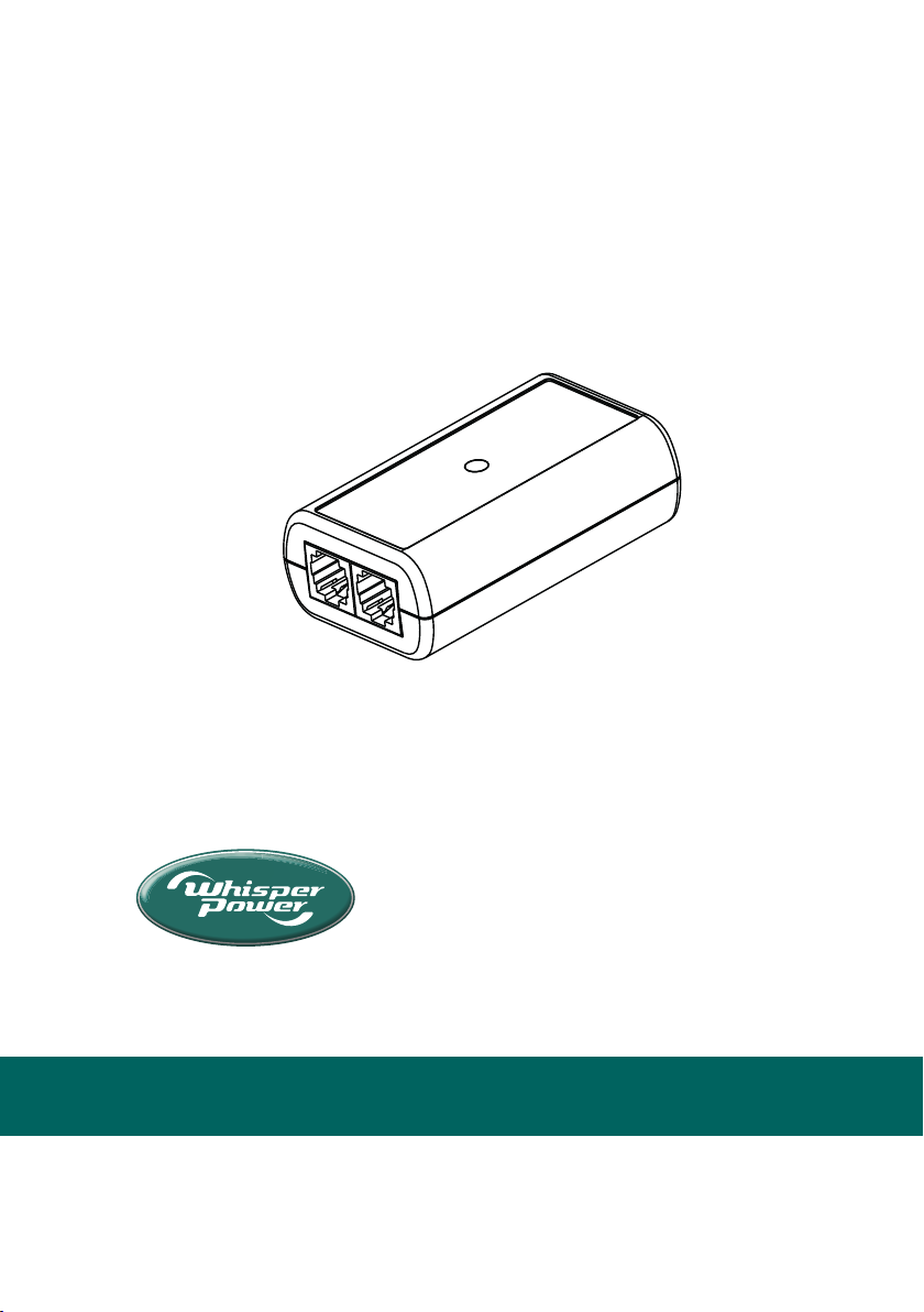
EN WBM Link to NMEA 2000 interface kit installation and setup guide
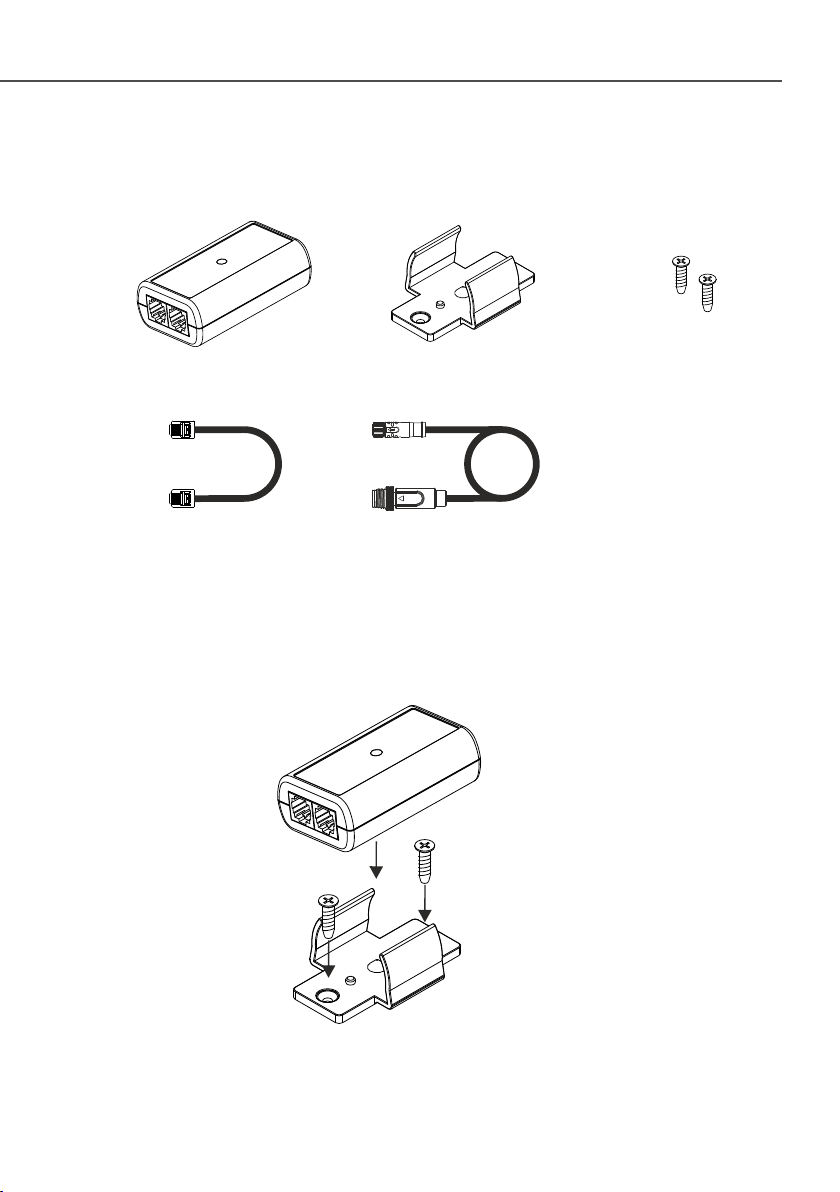
Package contents
QuickLink to NMEA 2000 Installation Guide rev1e
1
Interface box Mounting bracket Mounting screws
WBM Link cable NMEA 2000 drop cable
2Mounting the interface box
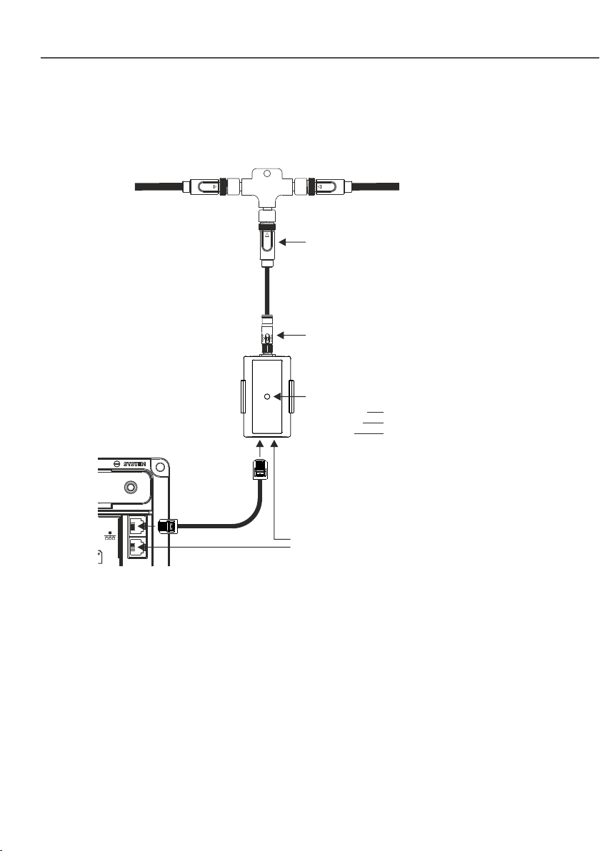
3Connecting the interface box
QLINK
Additional WBM Link port for connecting other WBM
Link accessories (see notes in chapter 10 for
additional information)
flashing orange
flashing green
flashing red
Introduction
4
LED conditions:
waiting for WBM Link connection
normal operation / data indicator
Communication error
active shunt
Battery monitor
NMEA 2000 network
backbone
M8 female cable connector. Insert in
male chassis connector and gently
turn plastic ring clockwise for locking
M12 male cable connector. Insert in
male T-piece connector and gently
turn plastic ring clockwise for locking
§State-of-Charge
§Nominal Voltage
§Ba�ery Capacity
§Temperature
§Amp-Hours removed
The WBM Link to NMEA 2000 interface forms a bridge between WBM Link
enabled devices and an NMEA 2000 network. Currently it only supports the
WBM Modular Smart Shunt ba�ery monitor.
The interface presents the following parameters on the NMEA 2000 network.
§Current
§Time Remaining
§Voltage
§Ba�ery Type
Only the parameters of ba�ery bank 1 are available.
Changing of device- and ba�ery instance is fully supported by this interface,
allowing multiple WBM Modular Smart Shunt on the NMEA 2000 network, with
each WBM Modular Smart Shunt having its own WBM Link to NMEA 2000
interface. A proper NMEA 2000 network management tool is needed to change
device- and ba�ery instance. Such a tool is not provided by us.
It is assumed that the user of this device has a good understanding of the NMEA
2000 standard.
NMEA 2000 Interface Standard
5
The NMEA 2000 standard contains the requirements of a serial data
communicaons network to inter-connect marine electronic equipment on
vessels. It is mul-master and self-configuring, and there is no central network
controller. Equipment designed to this standard will have the ability to share data,
including commands and status with other compable equipment over a single
channel. It is based on CAN (Controller Area Network). NMEA 2000 is a registered
Trademark of the Naonal Marine Electronics Associaon.
Supported PGNs
6
The following PGNs are transmi�ed by the interface. These may be broadcasted,
sent on request, or as acknowledgment.
60416 ISO Transport Protocol, Connecon Management – RTS Group Funcon
60160 ISO Transport Protocol, Data Transfer
59392 ISO Acknowledgment
60928 ISO Address Claim
PGN Name
126208 NMEA – Request Group Funcon
126464 PGN List – Received / Transmit PGNs Group Funcon
127502 Switch Bank Control
126998 Configuraon Informaon
126996 Product Informaon
127508 Ba�ery Status
127506 DC Detailed Status
126993 Heartbeat
See backside of this paper for connuaon.
127513 Ba�ery Configuraon Status
Changing Instances
7
PGN Name
Instance Default value
Changing a PGN’s transmission interval
8
PGN Name Default interval (ms)
Switch Bank Control
9
1. WBM
2. WBM
WBM | Art. Nr. 40290316
WBM
WBM Modular Smart Shunt
WBM Modular Smart Shunt
WBM Modular
Smart Shunt
WBM Modular Smart Shunt
10 Specifications plus notes
6. Supported PGNs
7. Changing Instances