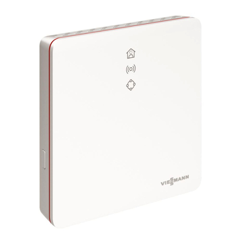
Viessmann Vitocom 100 Operating instructions

Installation and service instructions
for contractors
VIESMANN
Vitocom 100
Type GSM2
Communication interface for remote monitoring and remote control of a heating
system via the mobile network
For applicability, see the last page
VITOCOM 100
5782 267 GB 2/2015 Please keep safe.

2
Please follow these safety instructions closely to
prevent accidents and material losses.
Safety instructions explained
Danger
This symbol warns against the risk of injury.
!Please note
This symbol warns against the risk of material
losses and environmental pollution.
Note
Details identified by the word "Note" contain additional
information.
Target group
These instructions are exclusively intended for author-
ised contractors.
■Work on gas installations must only be carried out by
a registered gas fitter.
■Work on electrical equipment must only be carried
out by a qualified electrician.
■The system must be commissioned by the system
installer or a qualified person authorised by the
installer.
Regulations to be observed
■National installation regulations
■Statutory regulations for the prevention of accidents
■Statutory regulations for environmental protection
■Codes of practice of the relevant trade associations
■All current safety regulations as defined by DIN, EN,
DVGW, TRGI, TRF, VDE and all locally applicable
standards
aÖNORM, EN, ÖVGW-TR Gas, ÖVGW-TRF and
ÖVE
cSEV, SUVA, SVGW, SVTI, SWKI, VKF and
EKAS guideline 1942: LPG, part 2
Safety instructions for working on the system
Working on the system
■Where gas is used as the fuel, close the main gas
shut-off valve and safeguard it against unintentional
reopening.
■Isolate the system from the power supply, e.g. by
removing the separate fuse or by means of a mains
isolator, and check that it is no longer 'live'.
■Safeguard the system against reconnection.
Danger
Hot surfaces can cause burns.
■Before maintenance and service work, switch
OFF the appliance and let it cool down.
■Never touch hot surfaces on the boiler, burner,
flue system or pipework.
!Please note
Electronic assemblies can be damaged by elec-
trostatic discharge.
Prior to commencing work, touch earthed
objects such as heating or water pipes to dis-
charge static loads.
Repair work
!Please note
Repairing components that fulfil a safety func-
tion can compromise the safe operation of the
system.
Replace faulty components only with genuine
Viessmann spare parts.
Auxiliary components, spare and wearing parts
!Please note
Spare and wearing parts that have not been tes-
ted together with the system can compromise its
function. Installing non-authorised components
and making non-approved modifications or con-
versions can compromise safety and may inva-
lidate our warranty.
For replacements, use only original spare parts
supplied or approved by Viessmann.
Safety instructions for operating the system
If you smell gas
Danger
Escaping gas can lead to explosions which may
result in serious injury.
■Never smoke. Prevent naked flames and
sparks. Never switch lights or electrical appli-
ances on or off.
■Close the gas shut-off valve.
■Open windows and doors.
■Evacuate any people from the danger zone.
■Notify your gas or electricity supply utility from
outside the building.
■Have the power supply to the building shut off
from a safe place (outside the building).
If you smell flue gas
Danger
Flue gas can lead to life threatening poisoning.
■Shut down the heating system.
■Ventilate the installation site.
■Close doors to living spaces to prevent flue
gases from spreading.
Safety instructions
Safety instructions
5782 267 GB
3
What to do if water escapes from the appliance
Danger
When water escapes from the appliance there is
a risk of electrocution.
Switch off the heating system by means of an
external isolator (for example fuse box, domestic
power distribution).
Flue systems and combustion air
Ensure that flue systems are clear and cannot be
sealed, for instance due to accumulation of conden-
sate or other causes. Ensure an adequate supply of
combustion air.
Instruct system users that subsequent modifications to
the building characteristics are not permissible (e.g.
cable/pipework routing, cladding or partitions).
Danger
Leaking or blocked flue systems, or an inade-
quate supply of combustion air can cause life
threatening poisoning from carbon monoxide in
the flue gas.
Ensure the flue system is in good working order.
Apertures for supplying combustion air must be
non-closable.
Extractors
Operating appliances that extract air to the outside
(cooker hoods, extractors, air conditioning units, etc.)
can create negative pressure. If the boiler is operated
at the same time, this can lead to reverse flow of the
flue gas.
Danger
The simultaneous operation of the boiler and
appliances that extract air to the outside can
result in life threatening poisoning due to
reverse flow of the flue gas.
Fit an interlock circuit or take suitable steps to
ensure an adequate supply of combustion air.
Safety instructions
Safety instructions (cont.)
5782 267 GB

4
1. Safety and liability Operational reliability ............................................................................. 6
■Liability ................................................................................................ 6
2. Information Symbols ................................................................................................. 7
Intended use .......................................................................................... 7
3. Preparing for installation System requirements ............................................................................. 8
■Heating system ................................................................................... 8
■Supported heat generators ................................................................. 8
■Mobile network ................................................................................... 8
Functions ............................................................................................... 9
■Summary of functions ......................................................................... 9
4. Installation sequence Sequence overview ............................................................................... 10
Installing wall mounting bracket ............................................................. 10
Removing the cover ............................................................................... 11
Inserting the SIM card ............................................................................ 11
5. Electrical connections Overview of connections ........................................................................ 13
Connecting the Vitocom 100 to the Vitotronic control unit ..................... 13
Connecting the aerial ............................................................................. 14
Connecting digital input DI1 ................................................................... 14
Connecting the power supply ................................................................ 14
Closing the wiring chamber ................................................................... 15
6. Commissioning Display and operating elements ............................................................ 16
■Interpreting the LED indicators ........................................................... 16
Commissioning – overview .................................................................... 17
Initialisation successful .......................................................................... 17
■Reception quality ................................................................................ 17
Initialisation unsuccessful ...................................................................... 18
Function test .......................................................................................... 18
Notes on SMS commands ..................................................................... 18
■SMS commands ................................................................................. 18
Reply SMS ............................................................................................. 19
Sample SMS .......................................................................................... 19
Changing the access code .................................................................... 19
■SMS command "Code" ....................................................................... 19
Setting the language .............................................................................. 19
■SMS command "sprache" ................................................................... 19
Entering the current date ....................................................................... 20
Entering information texts ...................................................................... 20
■SMS command "info" ........................................................................ 20
■SMS command "ditext" ..................................................................... 20
Entering a mobile phone number ........................................................... 21
■SMS commands "mobnr1" and "mobnr2" ....................................... 21
■Deleting "mobnr2" ............................................................................. 21
7. Service functions Entering operating mode changeover .................................................... 22
Entering the PIN .................................................................................... 22
Entering the PIN at Vitotronic control units ............................................ 23
■Control unit for constant temperature operation ................................. 23
■Control unit for weather-compensated operation ............................... 23
Entering the PUK ................................................................................... 23
Sending a commissioning SMS ............................................................. 24
■Reply SMS .......................................................................................... 24
Creating SMS templates on mobile phones .......................................... 24
Enabling the maintenance function ........................................................ 24
Index
Index
5782 267 GB

5
8. Credit monitoring Validity of SIM card ................................................................................ 26
■Entering the SIM card end date .......................................................... 26
■SIM card runtime ................................................................................ 26
■Entering SIM card credit (prepaid) ...................................................... 26
■Entering the cost of sending an SMS (prepaid) .................................. 26
■Credit warning (prepaid) ..................................................................... 27
9. Diagnosis and service
scans
Calling up the access code .................................................................... 28
Scanning current settings ...................................................................... 28
Display when sending an SMS .............................................................. 28
10. Troubleshooting Troubleshooting measures .................................................................... 29
Re-starting and returning settings to their default .................................. 30
■SMS command "reset" ...................................................................... 30
Reinstate delivered condition ................................................................. 30
11. Upkeep Regular function testing ......................................................................... 31
12. Parts lists Ordering parts ........................................................................................ 33
Parts list ................................................................................................. 34
13. Specification .................................................................................................................. 36
14. Certificates Declaration of conformity ....................................................................... 37
15. Keyword index .................................................................................................................. 38
Index
Index (cont.)
5782 267 GB

6
Danger
The Vitocom radio signals (when communicating
via mobile phone) may cause interference, par-
ticularly with pacemakers, hearing aids and
defibrillators.
If any such equipment is used, avoid the imme-
diate vicinity of the operational Vitocom.
The Vitocom 100 only relays faults occurring in the
connected Vitotronic control units and in the compo-
nents connected to the configured input of the
Vitocom.
Further information regarding transmitted mes-
sages:
Installation and service instructions for the
Vitotronic control units or heat sources
The full range of functions is only available if the fol-
lowing conditions are met:
■The Vitotronic control units and the Vitocom 100
must be connected and configured correctly.
■The SIM card must be enabled.
■The message destinations of the Vitocom 100 must
be set up correctly.
■To ensure that messages can still be sent if there is a
power failure, we recommend connecting the
Vitocom 100 to the power supply via a UPS (on site).
Note
■The heating system and the functionality of the mes-
sage paths must be checked at regular intervals.
■To further improve the operational reliability of the
heating system, we recommend implementing sup-
plementary measures, e.g. frost protection or moni-
toring for water damage.
Liability
Viessmann accepts no liability for loss of profit, unat-
tained savings, or other direct or indirect consequential
losses resulting from the use of Vitocom 100, nor for
losses resulting from inappropriate use.
The limitation of liability shall not apply if the damage
was caused by Viessmann deliberately or through
gross negligence, or if mandatory liability applies due
to product liability legislation.
The Viessmann General Terms and Conditions apply,
which are included in each current Viessmann pricelist.
Viessmann accepts no liability for SMS, email or fax
services, which are provided by network operators.
The terms and conditions of the respective network
operators apply in this context.
Safety and liability
Operational reliability
5782 267 GB
Information

7
Symbol Meaning
Reference to other document containing
further information
1.
Step in a diagram:
The numbers correspond to the order in
which the steps are carried out.
Warning of material losses and environ-
mental pollution
Live electrical area
Pay particular attention.
■Component must audibly click into place.
or
■Acoustic signal
■Fit new component.
or
■In conjunction with a tool: Clean the sur-
face.
Dispose of component correctly.
Dispose of component at a suitable collec-
tion point. Do not dispose of component in
domestic waste.
Intended use
The device is intended exclusively for remote control-
ling systems with Viessmann heat sources and for
remote monitoring systems with Viessmann heat sour-
ces and third party systems. The device is intended to
be installed and operated in conjunction with Vitotronic
control units only, with due attention paid to the associ-
ated installation, service and operating instructions.
Power is supplied exclusively via the plug-in power
supply unit supplied.
Intended use presupposes that a sufficient reception
level (mobile network) is present and that the SIM card
is approved by Viessmann and enabled by the mobile
phone provider. Message destinations must be set up
correctly.
Information
Symbols
5782 267 GB
Information

8
Heating system
■The Vitocom 100, type GSM2 is intended for 1 heat-
ing system with or without heating circuits down-
stream.
■The control unit is connected to the Vitocom 100 via
KM BUS.
■Standard 230 V/50 Hz socket
Supported heat generators
Current lists of supported heat generators:
Control units for floorstanding boilers:
■Vitotronic 100, type GC1B, GC4B, KC2B, KC4B
■Vitotronic 200, type GW1B, KO1B, KO2B, KW6B,
FO1
■Vitotronic 300, type GW2B, GW4B
Control units for wall mounted and storage combi boil-
ers:
■Vitotronic 100, type HC1B, HC2B
■Vitotronic 200, type HO1B
■Vitotronic 200 RF, type HO1C
Heat pump control units:
■Vitotronic 200, type WO1B, WO1C
Heating circuit control units:
■Vitotronic 200-H, type HK1B, HK3B
Third party systems:
■Connection via digital input
Mobile network
■Check that there is an adequate mobile network sig-
nal at the Vitocom 100 aerial prior to installation;
check with mobile phone if necessary.
■Request SIM card activation at least 3 days before
commissioning.
For further information on activation/registration see
the supplied envelope.
■Depending on your order, use either the supplied
SIM card or a SIM card approved by Viessmann.
SIM card requirements:
■SMS enabled
■Bi-directional SMS communication (sending and
receiving)
SIM cards approved for use with the Viessmann
Vitocom (see also www.vitocom.info):
■T-Mobile (standard for Vitocom 100 with SIM card)
■Vodafone
■E-Plus
Note
The SIM cards have been tested at a reference loca-
tion. Perfect operation cannot be guaranteed in every
regions.
Message paths / Message destinations
■Mobile phone for receiving and sending messages
by SMS.
Up to 2 mobile phones can be specified as message
destinations.
Important information regarding system limitations
■The range of the Vitocom 100 functions has only
been tested with the specified SIM cards. The appli-
cation test for the Vitocom 100 was carried out at the
time of publication of this document. The perfect
function of the Vitocom 100 can only be guaranteed
with tested SIM cards.
■The sending of SMS messages is a service provided
by the mobile phone network operator. We cannot
accept liability for the availability of the fully range of
functions of the Vitocom 100 if changes are imple-
mented by the mobile phone operator.
■The full range of functions of the Vitocom 100 has
not been tested with every type of mobile phone.
Although no limitations were detected with any of the
tested mobile phones, the perfect function of the
Vitocom 100 cannot be guaranteed for all available
mobile phones.
Preparing for installation
System requirements
5782 267 GB
Installation

9
Summary of functions
E
BC
A
D
F
Fig.1
AViessmann control unit
BKM BUS cable
CVitocom 100
DAerial with SMA connection
EMobile network
FMobile phone
Control functions
The operating mode of the heating circuits connected
to the control unit can be switched over.
Note
Connect the control unit to the Vitocom 100 via a KM
BUS.
Remote access
The following settings of the Vitocom 100 can be
accessed:
■2 mobile phone numbers that can be notified in case
of faults.
■SIM card credit (prepaid).
■Current date and expiry date of SIM card (prepaid).
■Cost of an SMS (stored value).
■Information text for naming the system and the digital
input.
■Selected language.
Message forwarding
Any pending messages from the heating system, e.g.
sensor or burner faults, are transmitted to the
Vitocom 100 via KM BUS. The Vitocom 100 sends
these messages to the programmed message destina-
tions.
Note
In a LON system, only the control unit that is connec-
ted to the Vitocom 100 via the KM BUS is monitored.
Message contents
■Message type
■Message code
■Message text
For information on messages, see installation and
service instructions for the Vitotronic control units or
the heat generator.
The following are automatically reported by SMS via
the mobile phone network:
■Faults
■Expiry of SIM card
■If an expiry date for the SIM card ("enddat") was
entered: Following a power failure, an SMS is sent
requesting the current date "aktdat" to be entered.
Example:
"aktdat" was deleted by a power failure. After the
power supply has been restored, the Vitocom 100
sends the following SMS alert to "mobnr1" and
"mobnr2":
SMS alert as request
1111þ Please enter AKTDAT
Preparing for installation
Functions
5782 267 GB
Installation

10
Sequence Responsibility Page
Installation
1 Checking system requirements. Heating contractor/IT contractor 8
2 Fitting the wall mounting bracket and opening the cas-
ing.
Heating contractor 10
3 Connecting the Vitocom 100 to the Vitotronic control
unit.
Heating contractor 13
4 Connecting the aerial. Heating contractor/system user 14
5 Connecting digital input DI1 (if required). Heating contractor 14
6 Inserting the SIM card. Heating contractor 11
7 Connecting the power supply. Heating contractor 14
Commissioning
8 Commissioning the Vitocom 100. Heating contractor 17
13 Initiating a heating system fault and checking the re-
porting chain
Heating contractor 18
Installing wall mounting bracket
!Please note
The installation site must be dry and free from
the risk of frost.
Safeguard ambient temperatures between 0 and
40 °C.
Note
When selecting the installation location, note the cable
lengths and the wireless reception at the aerial's inten-
ded location.
Connecting cables
(standard delivery)
Length
Aerial cable 3 m
KM BUS cable 3 m
Connecting cable for plug-in power
supply unit
Approx. 2 m
Installation sequence
Sequence overview
5782 267 GB
Installation

11
2.
3.
1.
Fig.2
Removing the cover
Fig.3
!Please note
When the power supply is connected, touching
electrical contacts can result in appliance dam-
age.
Always unplug the power supply unit before
removing the cover.
Inserting the SIM card
!Please note
The correct function of the Vitocom 100 cannot
be ensured with an untested SIM card.
Only use SIM cards that have been tested by
Viessmann (see the list of tested SIM cards at
www.vitocom.info).
Note
■If the SIM card was previously used in a mobile
phone, ensure that all stored SMS messages are
deleted from the SIM card.
■Check the position of the angled corner.
■Use an on-site adaptor (micro SIM to SIM) if a micro
SIM card is used.
Installation sequence
Installing wall mounting bracket (cont.)
5782 267 GB
Installation

12
1.
2.
4.
3.
5.
Fig.4
Installation sequence
Inserting the SIM card (cont.)
5782 267 GB
Installation

13
Fig.5
"1" Power supply unit connection, 5 V–, internal +,
external –, min. 1.6 A (see page 36)
"2" SMA connection for aerial
"3" Service interface: Never make any on-site con-
nections
"6" Digital input DI1, floating contact
"8" KM BUS connection
Note
For connections "6" and "8": To release the wires, push
the terminal up with a screwdriver.
Apply strain relief to all cables
Fig.6
Connecting the Vitocom 100 to the Vitotronic control unit
Note
If there are several KM BUS subscribers (e.g. remote
control), use a KM BUS distributor (part no. 7415 028,
accessories).
Total cable length of all KM BUS subscribers up to
50 m.
1. Connect the KM BUS cable via spring terminals to
connection "8" of the Vitocom 100 (see page 13).
For this, use a screwdriver to push up the spring.
Note
To release the wires, push the terminal up with a
screwdriver.
2. Connect the KM BUS cable to the Vitotronic control
unit:
"Vitotronic control unit" installation instruc-
tions
Electrical connections
Overview of connections
5782 267 GB
Installation

14
1. Connect the aerial cable to SMA connection "2" of
the Vitocom 100 (see page 13).
2. Insert the SIM card into a mobile phone and site the
aerial in a location with excellent reception quality.
A final check of the reception quality by the
Vitocom 100 can only take place after commission-
ing (see page 17).
Connecting digital input DI1
■For floating contacts, contact load 24 V−, 7 mA
■230 V signals must be hooked up via a coupling
relay (accessories).
■For capturing the switching state of external equip-
ment, e.g. fill level indicator
■DI1 is an N/O alarm contact.
External contacts must be floating. When making the
connection, adhere to the requirements of safety cate-
gory II.
A change in the switching state is registered by the
Vitocom 100 and sent as a message to the message
destinations.
Example:
Status reports from refrigeration, lifting and ventilation
systems and central fault messages from a control
panel
A
B
Fig.7
AVitocom 100
BDigital input DI1
1. Connect the floating N/O contact via a spring termi-
nal to connection "6" of the Vitocom 100. For this,
use a screwdriver to push up the spring.
Note
To release the wires, push the terminal up with a
screwdriver.
2. After commissioning the Vitocom 100, test the func-
tion of the connected N/O contact (switch the con-
tact and wait for the message).
Connecting the power supply
1. Insert the plug of the low voltage side of the sup-
plied plug-in power supply unit into connection "1"
of the Vitocom 100 (see page 13).
2. Closing the wiring chamber (see Fig. 8).
Electrical connections
Connecting the aerial
5782 267 GB
Installation

15
3. For connecting the plug-in power supply unit, see
chapter "Commissioning – overview" on page 17.
Closing the wiring chamber
Fig.8
Electrical connections
Connecting the power supply (cont.)
5782 267 GB
Installation

16
To remove the cover, see page 11.
Without cover With cover
A
3 4 T12
AType plate
SIMCARD Position of SIM card
"S1" PIN rotary selector (see page 22)
"T1" Maintenance button (see page 24)
"T2" Confirmation button for PIN entry (see
page 22)
"T3" No function
"T4" Reset button (see page 30)
"1" PIN entry indicator (green LED)
"2" Reception quality indicator (yellow, green
and red LED)
"3" Mobile network connection status indicator
(yellow and green LED)
"4" Operating status indicator (green and red
LED)
"5" Indicator, data transfer service interface
(green LED)
Interpreting the LED indicators
PIN entry indicator "1"
Flashes green. Only for PIN entry (see page 22)
Illuminates green.
Reception quality indicator "2"
Flashes yellow/flashes red/
illuminates red.
Reception quality indicator (see page 17)
SIM card fault (see page 29)
Flashes green. Only for PIN entry (see page 22)
Illuminates green.
Indicator for mobile network connection status "3"
Flashes yellow/illuminates
yellow.
■Establishing a connection to a mobile network or connection fault (see page 29)
or
■SIM card fault (see page 29)
Illuminates green. Only for PIN entry (see page 22)
Flashes green.
Commissioning
Display and operating elements
5782 267 GB
Commissioning

17
Operating status indicator "4"
Illuminates red. Maintenance enabled (see page 24)
Flashes red slowly. ■Heating system fault
■Digital input DI1 fault
■SIM card fault (see page 29)
Flashes red quickly. ■Internal Vitocom 100 fault
■SIM card fault (see page 29)
Flashes green for longer
than 5 min after start-up.
Fault when initialising the Vitocom 100 (see page 29)
Illuminates green. "Standard mode", no heating system or Vitocom 100 fault
Flashes green slowly. ■Vitocom 100 is initialising. Either the plug-in power supply unit has been inserted
or the reset button "T4" has been pressed.
or
■PIN entry (see page 22)
Flashes green quickly. Software update is being installed. The device must not be isolated from the mains.
Commissioning – overview
!Please note
If the connection values of the plug-in power
supply unit do not match the power consumption
of the Vitocom 100, this will lead to an interrup-
tion of operations and damage to the power sup-
ply unit or the Vitocom 100.
Only use the plug-in power supply unit supplied.
1. Plug the power supply unit into a standard 230 V~
socket.
Note
Never plug into a socket that is controlled by the
heating system emergency stop switch.
Vitocom 100 is initialised (see "Initialisation").
2. When commissioning with a new SIM card
The operating status indicator "4" flashes green.
After approx. 2 min:
The reception quality indicator "2" and the mobile
network connection status indicator "3" flash yellow;
the operating status indicator "4" flashes red.
Enter SIM card PIN; see page 22.
3. Note
After entering the PIN, the Vitocom 100 is commis-
sioned exclusively via SMS messages using a
mobile phone.
Send the commissioning SMS to the Vitocom 100
(see page 24).
4. Optional:
Create SMS templates in the mobile phone (see
page 24).
5. Only for prepaid SIM cards:
■Enter the current date (see page 20) and expiry
date of the SIM card (see page 26).
■Enter credit on SIM card and cost of an SMS for
monitoring the credit on the prepaid SIM card
(see page 26).
Initialisation successful
The Vitocom 100 is ready for operation. The following
LED indicators illuminate green: operating status indi-
cator "4" and mobile network connection status "3".
Depending on reception quality indicator "2" (see fol-
lowing table), align the aerial or select another installa-
tion location.
Reception quality
Continuous operation is only guaranteed if reception
quality indicator "2" illuminates green.
Commissioning
Display and operating elements (cont.)
5782 267 GB
Commissioning

18
Reception quality indicator
"2"
Flashes
red
Illumi-
nates red
Flashes
yellow
Illumi-
nates yel-
low
Flashes
green
Illumi-
nates
green
Current reception quality
1 – 16 %
17 – 32 %
33 – 50 %
51 – 66 %
67 – 84 %
85 – 100 %
Initialisation unsuccessful
If a fault occurs during initialisation, this is indicated by
the associated LED indicators. For troubleshooting
measures, see page 29.
Function test
1. Simulate a fault in the heating system, e.g. sensor
fault.
Vitotronic control unit or heat generator serv-
ice instructions
2. Check the following:
■Operating status indicator "4" (see page 16)
flashes red.
■The fault message is sent to the programmed
message destinations.
Note
■If a fault is rectified, this is confirmed by a message.
■If the fault is not rectified, a repeat message is sent
to all programmed message destinations every 24 h.
Notes on SMS commands
SMS commands
The Vitocom 100 is operated solely by SMS messages
via a mobile phone.
Observe the following principles when sending an
SMS to the Vitocom 100:
■The access code must always be at the start of the
SMS command.
■Several SMS commands can be combined into one
SMS (except for "reset" commands).
■A space þ is always required between the access
code and one or more commands.
■The text length of an SMS command is restricted to
70 characters. If the text is longer it will be trimmed
after the final permitted character.
■SMS commands may be composed in upper or lower
case.
Commissioning
Initialisation successful (cont.)
5782 267 GB
Commissioning

19
■Every SMS received by the Vitocom 100 is acknowl-
edged with a reply SMS.
–"OK": Command successful
–"ERROR": Command not carried out (error)
■The Vitocom 100 always sends the reply SMS
(acknowledgement) to both mobile phone numbers
"mobnr1" and "mobnr2" (if provided).
■If the reply SMS is longer than 70 characters, it is
transmitted in several replies.
Sample SMS
3 commands combined in one SMS
1. Change to access code
■accepted
2. Change to mobile phone number 2
■accepted
3. Change to operating mode (0 = DHW only) of heat-
ing circuit 4
■Error
(Only 3 heating circuits permitted)
SMS from the user
1111þcodeþ2345
þmobnr2þ017198765432
þbahk4þ0
Reply SMS as confirmation and error message
2345 CODE 2345 OK MOBNR2 017198765432 OK
BAHK4 0 ERROR
Changing the access code
SMS command "Code"
■Delivered condition is "1111".
■Enter only 4-digit access code (numbers 0 to 9); lon-
ger inputs will be trimmed.
■Immediately after input, the Vitocom 100 automati-
cally sends the new access code by SMS to the
mobile phone numbers.
■Update SMS templates (see page 24) with new
access code.
Example:
Changing the access code from "1111" to "1234",
for example.
SMS from the user
1111þcodeþ1234
Reply SMS as confirmation and error message
1234 CODE 1234 OK
Setting the language
SMS command "sprache"
Language options:
cs Czech
da Danish
de German
en English
es Spanish
et Estonian
fr French
hu Hungarian
it Italian
lv Latvian
lt Lithuanian
nl Dutch
pl Polish
ru Russian
sk Slovakian
sv Swedish
Example:
Setting the language to "English".
SMS from the user
1111þspracheþen
Reply SMS as confirmation and error message
1111 SPRACHE en OK
Commissioning
Reply SMS
5782 267 GB
Commissioning

20
Note
Scanning, see page 28.
Entering the current date
Entering or changing the current date.
The date can be specified in the following formats:
■D.M.YY or D.M.YYYY
■DD.MM.YYYY or DD.MM.YY
Example:
SMS from the user
1111þaktdatþ11.02.2015
Reply SMS from the Vitocom 100
1111 AKTDAT 11.02.2015 OK
Example:
Message in the case of incorrect input:
The current date "aktdat" that has been entered is later
than the end date "enddat".
The Vitocom 100 sends the following SMS alert:
SMS alert as error message
1111
ENDDAT 10.02.2015 ERROR
AKTDAT 11.02.2015 ERROR
Entering information texts
Information texts serve to name the heating system or
the appliances connected via the digital input. These
texts are sent by SMS for clear assignment, e.g. within
a fault message.
The text input is limited to 30 characters, longer texts
will be trimmed.
Note
Take care not to enter any terms that will trigger com-
mands, e.g. "code", as these will result in a termina-
tion.
SMS command "info"
Information text for naming the heating system. The
text can contain the name of the system user or the
location of the system, for example.
Example:
SMS from the user
1111þinfoþHeating system xyz
Reply SMS from the Vitocom 100
1111 INFO Heating system xyz OK
Note
Scanning, see page 28.
SMS command "ditext"
Naming of the device connected to the digital input or
its function.
Example:
Monitoring the fuel oil level.
SMS from the user
1111þditextþLow oil level
Reply SMS from the Vitocom 100
1111 DITEXT Low oil level OK
Note
Scanning, see page 28.
Commissioning
Setting the language (cont.)
5782 267 GB
Commissioning
Other manuals for Vitocom 100
8
This manual suits for next models
1
Table of contents
Other Viessmann Recording Equipment manuals

Viessmann
Viessmann 5556 User manual

Viessmann
Viessmann VITOCONNECT 100 Operating instructions

Viessmann
Viessmann 5560 User manual

Viessmann
Viessmann 5556 Instructions and recipes

Viessmann
Viessmann 55 Series User manual

Viessmann
Viessmann 5559 Instructions and recipes

Viessmann
Viessmann 5560 User manual

Viessmann
Viessmann 5572 User manual

Viessmann
Viessmann 5577 User manual

Viessmann
Viessmann 5569 User manual