White Rodgers 1F85RF-275 User manual

1
1F85RF-275
Wireless Remote Kit
Read Installer Notes
before removing cover
from Thermostat.
IMPORTANT
Do not remove battery tags to activate the
thermostat or wireless sensor until instructed to
do so.
For proper operation of the RF wireless
communication, when installing:
zAvoid locating thermostat or sensor near any
wireless or noise generating devices, particularly
radio devices that operate in the range of 418 to
428 MHz.
zBe sure that there are no electrical wires, metal
pipes or ductwork in the part of the wall chosen for
thermostat or sensor location
zAvoid locating the thermostat or sensor on a
concrete wall, metal junction box or metal plate.
zThermostat antenna wire must be installed into the
wall.Do not allow the antenna wire to be between
the thermostat and the wall.
zThermostat must have uninterrupted 24VAC for
proper communication.
System Power
Thermostat is received from the factory for system
power to be hardwired with a common wire connected to
terminal C. If no common wire is available, the thermo-
stat will use Power Stealing and must be configured.
See Thermostat 24VAC Requirement on page 5.
This device complies with Part 15 of the FCC Rules.
Operation is subject to the following two conditions:
(1) this device may not cause harmful interference, and
(2) this device must accept any interference received,
including interference that may cause undesired
operation.
www.white-rodgers.com PART NO. 37-6841CPART NO. 37-6841C
PART NO. 37-6841CPART NO. 37-6841C
PART NO. 37-6841C
Replaces 37-6841B
0810
FAILURE TO READ AND FOLLOW ALL
INSTRUCTIONS CAREFULLY BEFORE
INSTALLING OR OPERATING THIS
CONTROL COULD CAUSE PERSONAL INJURY
AND/OR PROPERTY DAMAGE.
!
QUICK INSTALLATION GUIDE
INSTALLER NOTES
Index Page
Wireless Remote Kit Installation 2
Applications 4
Specifications 4
Installation 5
Wiring Connections 6
Thermostat/Sensor Quick Reference 8
Installer Configuration Menu 10
Operating Your Thermostat and Sensor 14
Programming 17
Troubleshooting 18
Any of the above can diminish or prevent proper
RF communication for this kit. Be sure to perform
a thorough checkout and confirm signal strength
between thermostat and wireless sensor.

2
System power must be turned off before
beginning installation and battery power not
activated.
1Mount thermostat
Position and mount thermostat on wall following
standard installation procedures. Questions on
installation, see Guidelines for Thermostat/Sensor
Locations and Mounting Thermostat and Sensor on
page 5.
When system power is turned on, if the display is
blank, the thermostat is not receiving 24VAC.
3Configure thermostat
Configure thermostat for operation with system.
Refer to Thermostat Configuration beginning on
page 10. If the remote sensor is to be an indoor
sensor, on Step 4, change Remote Off to Remote
On to enable the indoor sensor.
When the configuration menu is exited, the display
will indicate the indoor sensor is enabled.
4Provide battery power to remote sensor
and check sensor transmission
2
Connect wires to thermostat
Connect wires following standard wiring procedures.
Questions on wiring, see system diagrams on page 7.
24 VAC Requirement
The thermostat must have 24VAC to operate. If a
common wire is connected to terminal C, the
system is providing 24VAC to the thermostat and
the RC/PS switch (S7) should be in the RC posi-
tion. (See Figure 1 on page 5) Proceed to step 3.
If the thermostat does not have a common wire
connected to terminal C, the RC/PS switch must be
in the PS position to allow Power Stealing.
Antenna Wire – When installing the thermostat,
antenna wire must be installed into the wall for
proper communication between the thermostat
and the remote sensor.
Now, remove Battery Tag only from remote sensor
to provide power. Do not remove Battery Tag from
thermostat.
Enable the Learn mode of the remote sensor to
confirm that remote sensor is transmitting and
thermostat is receiving. Press and keys at
the same time and hold for approximately five
seconds. When keys are released, display will
show OFF and Learn. Press to change OFF to
ON. Then press both keys at the same time three
more times to exit the menu. The remote sensor
will be in the Learn mode and will transmit once
every 10 seconds for 10 minutes.
Place the sensor on the thermostat for the best
transmitting-receiving conditions.
QUICK INSTALLATION GUIDE
WIRELESS REMOTE KIT INSTALLATION
installed through wall
Thermostat Antenna Wire
Power Stealing – If the HVAC system does not
provide enough power, we recommend connecting
a 150 Ohm, 10 Watt resistor between terminals W
and C of the furnace or Y and C on the air
conditioner or both to increase the power provided.

3
Indicates
sensor is
transmitting
signal
Indicates
sensor is
receiving
signal
Signal
strength
5
Confirm that thermostat is receiving
The thermostat receiving icon and the sensor
transmitting icon will appear at the same time. The
thermostat display will show SIGNAL and the
strength of the signal, 3 bars high signal strength, 2
bars medium signal strength, and 1 bar low signal
strength. The display will also show the temperature
sensed by the remote sensor.
While the sensor is in Learn mode, the thermostat
should be receiving signals consistently (6 signals
in one minute).
6
Position Remote Sensor at installation
location
Once communication has been confirmed, move
remote sensor to permanent location. Do not mount
remote sensor or drill holes to mount
sensor yet.
Enable the remote sensor Learn
Mode again.
Have someone hold the remote
sensor at the desired mounting
location. Hold remote sensor on the
left side to avoid interference with
the transmitting antenna on the right
side.
Return to the thermostat and
confirm that good communication
with the thermostat can be estab-
lished as described in step 5. Ideal
consistency is 6 signals in 1 minute.
WIRELESS REMOTE KIT INSTALLATION
QUICK INSTALLATION GUIDE
7
Mount Remote Sensor
Once the ideal position is determined, mark mount-
ing holes for the remote sensor. The batteries will
have to be removed from the remote sensor to
access the mounting hole under them.
After mounting the remote sensor, reinstall the
batteries and enable the Learning Mode again.
Confirm that communication with the thermostat is
still good as describe in step 5.
8
Complete Installation
Now, remove Battery Tag from thermostat only.
Perform operation check of thermostat with heating
and cooling systems. Questions on thermostat
operation, see Check Thermostat Operation on
page 13.
Check Remote Sensor operation as described in
Remote Temperature Sensor Information on the
Thermostat Display on page 14.
The remote sensor will transmit when it senses a
temperature change of 3/16 of a degree from the
last transmission or after 10 minutes. The antenna
icons will turn on briefly to indicate the sensor is
transmitting and the thermostat is receiving.

1F85RF-275 Thermostat and
Wireless Remote Sensor Kit
Automatic Heat/Cool Changeover Thermostat for Single Stage/
Multi-Stage/Heat Pump Systems with Wireless Remote Sensor
Installation and Operating Instructions for Model:Installation and Operating Instructions for Model:
Installation and Operating Instructions for Model:
Save these instructionsSave these instructions
Save these instructions
for future use!for future use!
for future use!
FAILURETOREADANDFOLLOWALLINSTRUCTIONSFAILURETOREADANDFOLLOWALLINSTRUCTIONS
FAILURETOREADANDFOLLOWALLINSTRUCTIONS
CAREFULLYBEFOREINSTALLINGOROPERATINGTHISCAREFULLYBEFOREINSTALLINGOROPERATINGTHIS
CAREFULLYBEFOREINSTALLINGOROPERATINGTHIS
CONTROLCOULDCAUSEPERSONALINJURYAND/ORCONTROLCOULDCAUSEPERSONALINJURYAND/OR
CONTROLCOULDCAUSEPERSONALINJURYAND/OR
PROPERTYDAMAGE.PROPERTYDAMAGE.
PROPERTYDAMAGE.
APPLICATIONSAPPLICATIONS
APPLICATIONS
DescriptionDescription
Description
Heat Pump (No Auxiliary or Emergency Heat) Yes
Heat Pump (with Auxiliary or Emergency Heat) Yes
Standard Heat & Cooling Systems Yes
Multi-Stage Systems requiring more than Yes
One Call for Heat or Cool
Standard Heat Only Systems Yes
Millivolt Heat Only Systems – Floor or Wall Furnaces No
Standard Central Air Conditioning Yes
Gas or Oil Heat Yes
Electric Furnace Yes
Hydronic (Hot Water) Zone Heat – 2 Wires * Yes
Hydronic (Hot Water) Zone Heat – 3 Wires No
THERMOSTATAPPLICATIONGUIDETHERMOSTATAPPLICATIONGUIDE
THERMOSTATAPPLICATIONGUIDE
ATTENTION:MERCURYNOTICEATTENTION:MERCURYNOTICE
ATTENTION:MERCURYNOTICE
This product does not contain mercury. However, this prod-
uct may replace a product which contains mercury.
Mercury and products containing mercury must not be dis-
cardedinhouseholdtrash. Do not touch any spilled mercury.
Wearingnon-absorbentgloves, cleanupanyspilled mercury
and place in a sealed container. For proper disposal of a
product containing mercury or a sealed container of spilled
mercury, place it in a suitable shipping container and send it
to: White-RodgersWhite-Rodgers
White-RodgersWhite-Rodgers
White-Rodgers
2895 Harrison Street2895 Harrison Street
2895 Harrison Street
Batesville, AR 72501Batesville, AR 72501
Batesville, AR 72501
Model Programming Choices
1F85RF-270 5/1/1 Day Non-Programmable
F145RF-1328 Wireless Remote Sensor
ThermostatThermostat
Thermostat:
Electrical Ratings .......................... 20 to 30 VAC 50/60 Hz
0.2 to 0.6 Amps per Load
(Y1, E/W1, G)
1.5 Amps (Y2, W2, O, B
Load per terminal)
1.5 Amps Max
(All terminals combined)
Setpoint Range.............................. 45 to 90°F (7 to 32°C)
Rated Differential (Single Stage)... Heat 0.6° or 1.5°F, Cool 1.2°F
Rated Differential (Multi-Stage)..... Heat 0.6° or 1.5°F, Cool 1.2°F
Rated Differential (Heat Pump)..... Heat & Cool 0.75° or 1.2°F
Operating Ambient ........................ 32 to +105°F (0 to +41°C)
Operating Humidity ....................... 90% non-condensing max.
Shipping Temp. Range.................. -4 to +150°F (-20 to +65°C)
Thermostat Dimensions ............... 3-3/4"H x 6"W x 1-1/4"D
Remote Sensor:Remote Sensor:
Remote Sensor:
This device complies with Part 15 of the FCC Rules, Operation isThis device complies with Part 15 of the FCC Rules, Operation is
This device complies with Part 15 of the FCC Rules, Operation is
subject to the following two conditions: (1) this device may notsubject to the following two conditions: (1) this device may not
subject to the following two conditions: (1) this device may not
cause harmful interference, and (2) this device must accept anycause harmful interference, and (2) this device must accept any
cause harmful interference, and (2) this device must accept any
interference received, including interference that may causeinterference received, including interference that may cause
interference received, including interference that may cause
undesiredoperation.undesiredoperation.
undesiredoperation.
Maximum Wireless Remote Sensors....1 indoor, 1 outdoor
Operating Range ....................................45 to 90°F (7 to 32°C)
Operating Humidity Range .....................0 to 90% RH
(non-condensing)
Dimensions .............................................2-5/8"H x 4-1/4"W x 7/8"D
* Max. Distance from Thermostat ..........200 feet
* Distance shown is for a typical application. Distances may vary in
some applications because obstacles that block the signal path
may affect the strength of the signal.
* Common Connection Required
1F85RF-270
Thermostat
F145RF-1328 Wireless
Remote Sensor
WARNING
!
Thermostat installation and all components of theThermostat installation and all components of the
Thermostat installation and all components of the
control system shall conform to Class II circuits per thecontrol system shall conform to Class II circuits per the
control system shall conform to Class II circuits per the
NEC code.NEC code.
NEC code.NEC code.
NEC code.
www.white-rodgers.com PART NO. 37-6841CPART NO. 37-6841C
PART NO. 37-6841CPART NO. 37-6841C
PART NO. 37-6841C
Replaces 37-6841B
0810
SPECIFICATIONSSPECIFICATIONS
SPECIFICATIONS

5
Figure 1 – Thermostat baseFigure 1 – Thermostat base
Figure 1 – Thermostat base
Figure 2 – Back of thermostat baseFigure 2 – Back of thermostat base
Figure 2 – Back of thermostat base
RC/PSRC/PS
RC/PSRC/PS
RC/PS
SwitchSwitch
SwitchSwitch
Switch
PositionPosition
PositionPosition
Position DescriptionDescription
DescriptionDescription
Description
RC For Hardwire Applications. Requires Common Wire
from System Transformer to "C" Terminal on Thermostat
PS For Power Stealing Applications. Use When Common
from the System Transformer is not Available for
Connection to the "C" Terminal on the Thermostat
RC/PS Switch (Thermostat Power Option)RC/PS Switch (Thermostat Power Option)
RC/PS Switch (Thermostat Power Option)
NOTE: If set to PS (Power Stealing), the thermostat "C" terminal
must notmust not
must notmust not
must not
have a wire connected.
When the system is not providing enough power for the
thermostat, the display will be bright when the system is not
running and dim when the system is running. If the system is
not providing enough power, we recommend connecting a
150 Ohm, 10 Watt resistor between terminals W and C of the
furnace or Y and C of the air conditioner, or both, to increase
the power provided.
ANTENNA
MOUNTING HOLE
MOUNTING HOLE
ELEC/GASSWITCH
RC/PS
SWITCH
MOUNTING
HOLE
CM/NO CM
SWITCH
MOUNTING
HOLE
ANTENNA
WIRE
Figure 3 – Remote sensor baseFigure 3 – Remote sensor base
Figure 3 – Remote sensor base
REMOTE
COMMUNICATION
RECEIVER
ANTENNA
WIRE
Thermostat 24 VAC RequirementThermostat 24 VAC Requirement
Thermostat 24 VAC Requirement
The thermostat must have 24 VAC supplied for the receiver
to operate. When the system wiring is connected, if a system
common wire is connected to terminal C, the system is
providing 24 VAC to the thermostat. The RC/PS switch (see
Fig 1) must be in the RC position.
If the thermostat does not have a common wire connected to
terminal C, the thermostat can use Power Stealing to get the
required 24 VAC. The RC/PS switch must be in the PS
posiition.
INSTINST
INSTINST
INSTALLAALLA
ALLAALLA
ALLATIONTION
TIONTION
TION
Do not remove battery tags to power the thermostat or sensor
with batteries until instructed to do so. The thermostat requires
24voltsystem power to operatecorrectly.Leavingthebatteries
disconnected during installation and check out will verify sys-
tem power is present. If the thermostat goes blank, system
power is not reliable and will be corrected in the System Power
section below.
1. Remove the packing material from the thermostat and
sensor.
2. Pull the front cover of the thermostat straight off the base.
Forcing or prying will cause damage to the control.
3. Using the thermostat base as a template, place on the
selected wall locations and mark the location of all
mounting holes (Figure 1), and the hole for the thermostat
antenna wire illustrated in Figure 2.
4. Move base out of the way and drill the holes. If mounting
holes drilled are too large and do not allow you to tighten
base snugly, use the plastic screw anchors (provided) for
secure mounting.
5. Make sure the remote communication receiver is
plugged in properly to the thermostat and that the
antenna wire is routed through the thermostat subbase
as shown in Figure 2.
6. Insert antenna wire into the wall and position base into
mounting position.
7. Fasten base loosely to wall, using two mounting screws.
Place a level against bottom of base (leveling is for
appearance only and will not affect sensor operation)
and then tighten screws.
Mounting Thermostat and SensorMounting Thermostat and Sensor
Mounting Thermostat and Sensor
CAUTION
!
To prevent electrical shock and/or equipment damage,To prevent electrical shock and/or equipment damage,
To prevent electrical shock and/or equipment damage,
disconnect electric power to system at main fuse ordisconnect electric power to system at main fuse or
disconnect electric power to system at main fuse or
circuit breaker box until power is required.circuit breaker box until power is required.
circuit breaker box until power is required.
Before disconnecting wires from the old thermostat, mark
wires for terminal identification so the proper wiring connec-
tions will be made to the new thermostat.
Remove Old ThermostatRemove Old Thermostat
Remove Old Thermostat
Locate the thermostat/sensor about 5 ft. above floor level on
an interior wall in an area that represents the average room
temperature.
Do not mount directly on or near HVAC equipment or other
sources of electrical noise.
Avoid locations close to windows or near adjoining outside
walls, doors leading outside, areas close to air registers or
their direct air flow or areas with poor circulation like alcoves.
Avoid locating the sensor on a concrete wall, junction box or
metal plate. Make sure there are no electrical wires, metal,
pipes or duct work in the part of the wall chosen for the
sensor location.
For proper RF wireless communication, the antenna wire
MUST be installed into the wall. If the antenna wire is
hanging between the wall and the themostat the RF commu-
nication may not be reliable
Antenna wire must be installed into the wall, it can not be
between the thermostat and wall.
Thermostat and indoor sensor are not approved forThermostat and indoor sensor are not approved for
Thermostat and indoor sensor are not approved for
installation in unconditioned space.installation in unconditioned space.
installation in unconditioned space.
Guidelines for Thermostat/Sensor LocationsGuidelines for Thermostat/Sensor Locations
Guidelines for Thermostat/Sensor Locations

6
INSTINST
INSTINST
INSTALLAALLA
ALLAALLA
ALLATIONTION
TIONTION
TION
8. In the thermostat location, push excess wire into wall and
plug hole with a fire resistant material (such as fiberglass
insulation) to prevent drafts from affecting the thermostat
operation.
9. Connect wires to thermostat terminals as required. Refer
to wiring diagrams Fig. 4 thru 7 for proper wiring.
10.Apply system power and confirm that thermostat display
is on and SYSTEM mode is OFF. Press SySTEM button
to OFF if necessary.
11.Enter the configuration as described in Thermostat
Configuration Menu on page 10. Configure the thermo-
stat for system operation. While in the configuration
menu, enable the indoor remote wireless sensor (item 4)
by changing OFF to ON.
Confirming Communication of RemoteConfirming Communication of Remote
Confirming Communication of Remote
Sensor to ThermostatSensor to Thermostat
Sensor to Thermostat
Before finding a good location to mount the remote sensor,
confirm that the thermostat is receiving the remote sensor
signals consistently and at the best strength possible.
Reliable Communication:Reliable Communication:
Reliable Communication: While the sensor is in the Learn
Mode,to besurethethermostatandsensorhavegood commu-
nication.Thethermostatreceivingiconandthesensortransmit-
ting icon will appear and turn off at about the same time. The
thermostat will display SIGNAL and the strength of the signal.
3 bars indicates a strong signal and the most desireable, 2 bars
indicates a medium strength signal and 1 bar indicates a weak
signal which is acceptable if it can not be improved. The
thermostatdisplaywillalsoshowthetemperaturesensedbythe
remote.Thethermostatshouldreceive6signalsin1minuteand
the signal strength should be 3 bars if possible.
1 Remove the battery tag from only the remote sensor. The
battery tag must still be in the thermostat.
2. On the remote sensor, begin the Learn mode so the remote
will transmit a signal once every 10 seconds for 10 minutes.
3. Place the remote sensor on the thermostat and check that
the thermostat is receiving signals from the sensor. Confirm
thatthesensorandthermostathavereliablecommunication
as described above in Reliable CommunicationReliable Communication
Reliable CommunicationReliable Communication
Reliable Communication.
4. Move the remote sensor to the room where it is to be
installed. Do not mark a mounting location or drill holes yet.
5. Enter the sensor learning mode again. Have someone hold
the remote sensor at the location selected fot the remote
sensor. Hold the remote sensor on the left side to avoid
interference with the transmitting antenna on the right side
of the sensor.
6. Return to the sensor and confirm that reliable communica-
tion with the sensor can be established again as described
in Reliable CommunicationReliable Communication
Reliable CommunicationReliable Communication
Reliable Communication. Have the sensor moved, if
necessary to improve the signal strength if it is not a consis-
tent signal with signal strength of 3 bars.
7. Once the ideal position for the sensor is determined, mark
mountingholesusing the sensor baseasatemplate(Figure
3). The batteries will have to be removed to access a
mounting under them.
8. Afterthesensorisfirmlyattachedtothewall,enterthesensor
Learning mode once again. Return to the Thermostat and
once again confirm that communication is still good as
described in Reliable CommunicationReliable Communication
Reliable CommunicationReliable Communication
Reliable Communication.
BatteryLocationBatteryLocation
BatteryLocation
The thermostat requires 2 "AA" alkaline batteries and the
sensor requires 2 "AAA" alkaline batteries. Batteries are
included at the factory with a battery tag to prevent power
drainage. The battery tag must be removed to engage the
batteries. For best results, replace batteries once a year with
new premium brand alkaline batteries such as Duracell®or
Energizer®.
Electric/Gas Switch (Fan Option)Electric/Gas Switch (Fan Option)
Electric/Gas Switch (Fan Option)
The ELEC/GAS switch on the thermostat (Fig. 1) is factory
set to the ELEC position. In this position, the thermostat will
power the circulator fan on a call for heat. Electric heat
systems may require the switch to be in the ELEC position.
If your system does not require that the thermostat power the
circulator fan, this switch should be set to the GAS position.
Typically, gas and oil heating systems do not require the
thermostat to power the circulator fan during a call for heat. If
your heat is gas or oil, the switch should be set to the GAS
position.
When the thermostat is configured for Heat Pump, the
thermostat will always power the circulator fan on a call for
heat in the HEAT mode. The ELEC/GAS switch must be set
to match the type of Auxiliary heat your system uses for
proper operation in the EMERgency mode.
Typical wiring diagrams are provided below for the following systems:
Single Stage Heat/Cool systems
Multi-Stage Heat/Cool systems (No Heat Pump)
Heat Pump system, one compressor or one speed compressor with Aux. Heat
Heat Pump systems, two compressors or two speed compressor with Aux. Heat
Refer to the equipment manufacturers instructions for specific wiring information. After completing the connections configure
the thermostat in the Installer Configuration Menu to match your system type.
WIRINGCONNECTIONSWIRINGCONNECTIONS
WIRINGCONNECTIONS

7
Heat Pump 1
(HP1)
Single
Compressor
Heat Pump
24 Volt
(Hot)
Blower/
Circulator
Fan Energized
on Call for
Heat/Cool
or Fan,
Note: Set
Elect/Gas
switch for
Emergency
Mode Heat Type
24 Volt
(Common)
Optional
Connection
System
*C
CLASS II
TRANSFORMER
HOT
24VAC
24VAC
COOL
HEAT NEUTRAL
120VAC
Fault
Indicator
for Heat
Pump
Systems
with
Malfunction
Switch
L
RE/W1
Y2 G
Emergency
Mode
1st Stage
Heat Mode-
1st Stage
Cool Mode-
1st Stage
(Compressor 1)
Y1 W2
Energized
in Cool
Mode
(Change-
over Valve)
O
Energized
in Heat, Off,
Emergency
Mode
(Change-
over Valve)
B
Heat Mode-
2nd Stage
Cool Mode-
2nd Stage
(Compressor 2)
Heat Pump 2
(HP2)
Two
Compressor
or Two Speed
Compressor
No Output
Heat
Mode
2nd Stage.
Emergency
Mode 2nd
Stage
Heat
Mode
3rd Stage.
Emergency
Mode 2nd
Stage
CUT AND
TAPE OFF
TWO COMMONS MUST
BE JUMPERED TOGETHER
HOT
NEUTRAL
120VAC
Multi-Stage
(MS2)
24 Volt
(Hot)
Blower/
Circulator
Fan Energized
on Call for
Cool or Fan,
Energized on
Call for Heat if
Elect/Gas
Switch Set to
Electric
24 Volt
(Common)
Optional
Connection
System
*C
CLASS II
TRANSFORMER
HOT
24VAC
NEUTRAL
120VAC
Fault
Indicator
for Heat
Pump
Systems
with
Malfunction
Switch
L
RE/W1
Y2 G
Heat
Mode
1st Stage
Cool Mode
1st Stage
(Compressor 1)
Y1
Heat
Mode
2nd Stage
W2
Energized
in Cool
Mode
(Change-
over Valve
or Damper)
O
Energized
in Heat, Off
Mode
(Change-
over Valve
or Damper)
B
Cool Mode
2nd Stage
(Compressor 2)
Figure 5 – Multi-Stage (No Heat Pump) Terminal OutputsFigure 5 – Multi-Stage (No Heat Pump) Terminal Outputs
Figure 5 – Multi-Stage (No Heat Pump) Terminal Outputs
Heat Pump 1
(HP1)
Single
Compressor
Heat Pump
24 Volt
(Hot)
Blower/
Circulator
Fan Energized
on Call for
Heat/Cool
or Fan,
Note: Set
Elect/Gas
switch for
Emergency
Mode Heat Type
24 Volt
(Common)
Optional
Connection
System
*C
CLASS II
TRANSFORMER
HOT
24VAC
NEUTRAL
120VAC
Fault
Indicator
for Heat
Pump
Systems
with
Malfunction
Switch
L
RE/W1
Y2 G
Emergency
Mode
1st Stage
Heat Mode-
1st Stage
Cool Mode-
1st Stage
(Compressor 1)
Y1 W2
Energized
in Cool
Mode
(Change-
over Valve)
O
Energized
in Heat, Off,
Emergency
Mode
(Change-
over Valve)
B
Heat Mode-
2nd Stage
Cool Mode-
2nd Stage
(Compressor 2)
Heat Pump 2
(HP2)
Two
Compressor
or Two Speed
Compressor
No Output
Heat
Mode
2nd Stage.
Emergency
Mode 2nd
Stage
Heat
Mode
3rd Stage.
Emergency
Mode 2nd
Stage
Figure 6 – Heat Pump Terminal OutputsFigure 6 – Heat Pump Terminal Outputs
Figure 6 – Heat Pump Terminal Outputs
Figure 7 – Heat Pump Terminal Outputs - Two Transformer with no Safety CircuitsFigure 7 – Heat Pump Terminal Outputs - Two Transformer with no Safety Circuits
Figure 7 – Heat Pump Terminal Outputs - Two Transformer with no Safety Circuits
WIRING CONNECTIONSWIRING CONNECTIONS
WIRING CONNECTIONS
* The RC/PS switch shown in Figure 1 configures the thermostat for Hardwire or Power Stealing.* The RC/PS switch shown in Figure 1 configures the thermostat for Hardwire or Power Stealing.
* The RC/PS switch shown in Figure 1 configures the thermostat for Hardwire or Power Stealing.
The factory setting is RC (Hardwire) and requires a Common connection from the system transformer to the "C" terminal on
the thermostat. If no common wire is available for the thermostat "C" terminal, move the RC/PS switch to PS (Power Steal-
ing). NOTENOTE
NOTENOTE
NOTE: If set to PS (Power Stealing), the thermostat "C" terminal
must notmust not
must notmust not
must not
have a wire connected.
Single Stage
(SS1)
24 Volt
(Hot)
Blower/
Circulator
Fan Energized
on Call for
Cool or Fan,
Energized on
Call for Heat if
Elect/Gas
Switch Set to
Electric
No Output
24 Volt
(Common)
Optional
Connection
System
*C
CLASS II
TRANSFORMER
HOT
24VAC
NEUTRAL
120VAC
Fault
Indicator
for Heat
Pump
Systems
with
Malfunction
Switch
L
RE/W1
Y2 G
Heat
Mode
1st Stage
(Heater)
Cool Mode
1st Stage
(Compressor)
Y1
No Output
W2
Energized
in Cool
Mode
(Change-
over Valve
or Damper)
O
Energized
in Heat, Off
Mode
(Change-
over Valve
or Damper)
B
Figure 4 – Single Stage (No Heat Pump) Terminal OutputsFigure 4 – Single Stage (No Heat Pump) Terminal Outputs
Figure 4 – Single Stage (No Heat Pump) Terminal Outputs

8
THERMOSTAT/REMOTESENSORQUICKREFERENCETHERMOSTAT/REMOTESENSORQUICKREFERENCE
THERMOSTAT/REMOTESENSORQUICKREFERENCE
Figure 8 – Thermostat display, buttons and switchesFigure 8 – Thermostat display, buttons and switches
Figure 8 – Thermostat display, buttons and switches
Before operating the thermostat, familiarize yourself with the
display and button functions. Both thermostat and remote
sensor consist of two parts: the cover and the base. To remove
acover,pullitstraightoutfromthebase.Toreplaceacover,line
it up with the base and press until the cover snaps into place on
the base.
The Thermostat Buttons and Switches and DisplayThe Thermostat Buttons and Switches and Display
The Thermostat Buttons and Switches and Display
1
Raises and lowers the temperature setting.
2
Light flashes every 20 seconds indicating acceptable
signal reception from indoor or outdoor remote sensor.
3Buttons for setting time (Time), programming (Prgm),
running program (Run) and bypassing program to
hold a constant temperature (Hold).
4
SYSTEM button (COOLCOOL
COOLCOOL
COOL, AUTOAUTO
AUTOAUTO
AUTO, HEATHEAT
HEATHEAT
HEAT, OFF, EMEROFF, EMER
OFF, EMEROFF, EMER
OFF, EMER
heat pump systems only).
5
FAN switch (ONON
ONON
ON, AUTOAUTO
AUTOAUTO
AUTO).
6
Displays the active temperature sensor (outside,
remote, local) and its sensed temperature if more than
one sensor is enabled.
7
Displays ( ) when in keypad lockout mode.
8
Indicates day of the week.
9
Indicates the thermostat mode information:
"HOLDHOLD
HOLDHOLD
HOLD" alternates with the system mode (see item 12)
if the HOLD button is pressed to bypass the program
and maintain a constant temperature.
10
Displays currently programmed set temperature (blank
when SYSTEMSYSTEM
SYSTEMSYSTEM
SYSTEM is OFFOFF
OFFOFF
OFF).
11
Alternately displays the current time and the tempera-
ture average of sensors (thermostat [local] and/or
indoor remote) turned on.
12
"HEATHEAT
HEATHEAT
HEAT" is displayed when set to heating,
"COOLCOOL
COOLCOOL
COOL" is displayed when set to cooling,
"AUTOAUTO
AUTOAUTO
AUTO" is displayed when set for automatic change-
over between heating and cooling.
When "AUTOAUTO
AUTOAUTO
AUTO" is displayed, the currently active mode
(Heat or Cool) will also display.
"EMEREMER
EMEREMER
EMER" is displayed flashing (heat pump systems
only) when the thermostat is set to the Emergency
Mode. Emergency is used to bypass the heat pump
and use only the back-up heating system.
"FLTRFLTR
FLTRFLTR
FLTR" is displayed as a reminder to change or clean
the air filter after system has run for the programmed
filter time period.
13
Stage 1 & 2 indicator.
"STG 1STG 1
STG 1STG 1
STG 1" indicates when the first stage heat or cool is
energized. "STG + 2STG + 2
STG + 2STG + 2
STG + 2" indicates when the second stage
heat or cool is energized. "+2" blinking indicates
Auxiliary Heat stages are energized on Heat Pump
Systems.
2
45
14
Displays "LRLR
LRLR
LR" when the limited range feature is
activated. Limited range limits the temperature the
thermostat can be set to.
15
Indicates the system is sending a fault signal to the
thermostat "L" terminal. This does not indicate a fault
in the thermostat.
16
Antenna will display for a few seconds when the remote
or outdoor transmitted signal is received.
17
Displays "LOW BATT" when the 2 "AA" batteries are
low and should be replaced.
18
Indicates the current signal strength level of the remote
temperature system. Signal strength level is low (one
bar on), medium (two bars on) or high (three bars on).
The remote will operate with 1 bar showing.
8
6
9
12
7
10
1311
14 15
17 18
16

9
1
2
THERMOSTAT/SENSORQUICKREFERENCETHERMOSTAT/SENSORQUICKREFERENCE
THERMOSTAT/SENSORQUICKREFERENCE
The Sensor Buttons and DisplayThe Sensor Buttons and Display
The Sensor Buttons and Display
1
Raises the setting.
2
Lowers the setting.
3Sensed temperature from –40 to 140°Fwith °Fand °C
indicator
4
Channel identification A B C O indicator
5
9 bar comfort adjust graph with H (hotter) and C (cooler)
6
Transmission occurrence indicator
7
Keypad lockout indicator
8
Calibrate temperature offset indicator
9
Learn mode activated indicator
10
Low battery indicator
11
Temperature offset used when hold time is active
12
Alternates PWR and on to indicate normal operation
with display turned OFF
Figure 9 – Remote Sensor display and buttonsFigure 9 – Remote Sensor display and buttons
Figure 9 – Remote Sensor display and buttons
ABCO
LOCK
LEARN
BATT
PWR HLD
H
CALIB
C
o
11 9
6
8
7
10
5
4
12
3
5
5
A
o
64
3
5
Normal OperationNormal Operation
Normal Operation
Configuration ItemsConfiguration Items
Configuration Items

10
PressPress
PressPress
Press DisplayedDisplayed
DisplayedDisplayed
Displayed PressPress
PressPress
Press oror
oror
or
StepStep
StepStep
Step Button(s)Button(s)
Button(s)Button(s)
Button(s) (Factory Default)(Factory Default)
(Factory Default)(Factory Default)
(Factory Default) to selectto select
to selectto select
to select CommentsComments
CommentsComments
Comments
1SystemSystem
SystemSystem
System MS2MS2
MS2MS2
MS2 SS1,HP2,HP1SS1,HP2,HP1
SS1,HP2,HP1SS1,HP2,HP1
SS1,HP2,HP1 Selects Single stage, Multi-stage, or Heat Pump
(Single stage or 2-stage) system configuration
2SystemSystem
SystemSystem
System LER(OFF)LER(OFF)
LER(OFF)LER(OFF)
LER(OFF) LER(ON)LER(ON)
LER(ON)LER(ON)
LER(ON) Selects learn mode OFF or ON
3SystemSystem
SystemSystem
System OUTSIDEOUTSIDE
OUTSIDEOUTSIDE
OUTSIDE(OFF)(OFF)
(OFF)(OFF)
(OFF) OUTSIDEOUTSIDE
OUTSIDEOUTSIDE
OUTSIDE(ON)(ON)
(ON)(ON)
(ON) Selects OUTSIDE sensor OFF or ON
4SystemSystem
SystemSystem
System REMOTEREMOTE
REMOTEREMOTE
REMOTE(OFF)(OFF)
(OFF)(OFF)
(OFF) REMOTEREMOTE
REMOTEREMOTE
REMOTE(ON)(ON)
(ON)(ON)
(ON) Selects REMOTE (indoor) sensor OFF or ON
5SystemSystem
SystemSystem
System LOCALLOCAL
LOCALLOCAL
LOCAL(ON)(ON)
(ON)(ON)
(ON) LOCALLOCAL
LOCALLOCAL
LOCAL(OFF)(OFF)
(OFF)(OFF)
(OFF) Selects LOCAL sensor ON or OFF
6SystemSystem
SystemSystem
System CHCH
CHCH
CH(0)(0)
(0)(0)
(0) 1 to 91 to 9
1 to 91 to 9
1 to 9 Select Receiver frequency offset
7SystemSystem
SystemSystem
System PRG4PRG 4
PRG4PRG 4
PRG4 PRG 0, PRG 2PRG 0, PRG 2
PRG 0, PRG 2PRG 0, PRG 2
PRG 0, PRG 2 Selects Programmable Periods
8SystemSystem
SystemSystem
System EMREMR
EMREMR
EMR(ON)(ON)
(ON)(ON)
(ON) EMREMR
EMREMR
EMR(OFF)(OFF)
(OFF)(OFF)
(OFF) Selects Energy Management Recovery OFF or ON
9SystemSystem
SystemSystem
System CR HEAT COOLCR HEAT COOL
CR HEAT COOLCR HEAT COOL
CR HEAT COOL (FA)(FA)
(FA)(FA)
(FA) SLSL
SLSL
SL Selects Fast or Slow cycle selection
10 SystemSystem
SystemSystem
System CLCL
CLCL
CL(OFF)(OFF)
(OFF)(OFF)
(OFF) CLCL
CLCL
CL(ON)(ON)
(ON)(ON)
(ON) Selects Compressor Lockout CL OFF or ON
11 SystemSystem
SystemSystem
System CdLCdL
CdLCdL
CdL(ON)(ON)
(ON)(ON)
(ON) CdLCdL
CdLCdL
CdL(OFF)(OFF)
(OFF)(OFF)
(OFF) Selects Backlight Display ON or OFF
12 SystemSystem
SystemSystem
System FA HEAT COOLFA HEAT COOL
FA HEAT COOLFA HEAT COOL
FA HEAT COOL (ON)(ON)
(ON)(ON)
(ON) FAHEAT COOLFA HEATCOOL
FAHEAT COOLFA HEATCOOL
FAHEAT COOL(OFF)(OFF)
(OFF)(OFF)
(OFF) Selects Fast Second Stage ON or OFF
13 SystemSystem
SystemSystem
System 0 FLTR0 FLTR
0 FLTR0 FLTR
0 FLTR 0–19500–1950
0–19500–1950
0–1950 (increments of 50)(increments of 50)
(increments of 50)(increments of 50)
(increments of 50) Selects filter replacement run time.0 =Disabled
14 SystemSystem
SystemSystem
System 0 F0 F
0 F0 F
0 F 4 LO to 4 HI4 LO to 4 HI
4 LO to 4 HI4 LO to 4 HI
4 LO to 4 HI Selects Temperature Display Adjustment 4 LO 4 HI
(Room Temperature)(Room Temperature)
(Room Temperature)
15 SystemSystem
SystemSystem
System 4:00HOLD4:00HOLD
4:00HOLD4:00HOLD
4:00HOLD 0:00 to 8:000:00 to 8:00
0:00 to 8:000:00 to 8:00
0:00 to 8:00 Selects Temporary Program Override Time
(Increments of 15 minutes)(Increments of 15 minutes)
(Increments of 15 minutes) 0:00 =Disabled
16 SystemSystem
SystemSystem
System FF
FF
FCC
CC
C For C selection
Selects temperature display as F° or C°
17 SystemSystem
SystemSystem
System LRHEATLRHEAT
LRHEATLRHEAT
LRHEAT (90)(90)
(90)(90)
(90) LR 62 to LR 89LR 62 to LR 89
LR 62 to LR 89LR 62 to LR 89
LR 62 to LR 89 Selects Limited HEAT range
18 SystemSystem
SystemSystem
System LRCOOLLRCOOL
LRCOOLLRCOOL
LRCOOL (45)(45)
(45)(45)
(45) LR 46 to LR 82LR 46 to LR 82
LR 46 to LR 82LR 46 to LR 82
LR 46 to LR 82 Selects Limited COOL range
19 SystemSystem
SystemSystem
System CACA
CACA
CA(OFF)(OFF)
(OFF)(OFF)
(OFF) CACA
CACA
CA(ON)(ON)
(ON)(ON)
(ON) Selects Comfort Alert Lock
20 SystemSystem
SystemSystem
System OFF LOCKOFF LOCK
OFF LOCKOFF LOCK
OFF LOCK ON LOCKON LOCK
ON LOCKON LOCK
ON LOCK Selects Buttonpad Lockout
21 0 00 LOCK0 00 LOCK
0 00 LOCK0 00 LOCK
0 00 LOCK 001 to 999001 to 999
001 to 999001 to 999
001 to 999 Selects Buttonpad lockout combination number
Press System to set code
RunRun
RunRun
Run Returns to the OFF mode
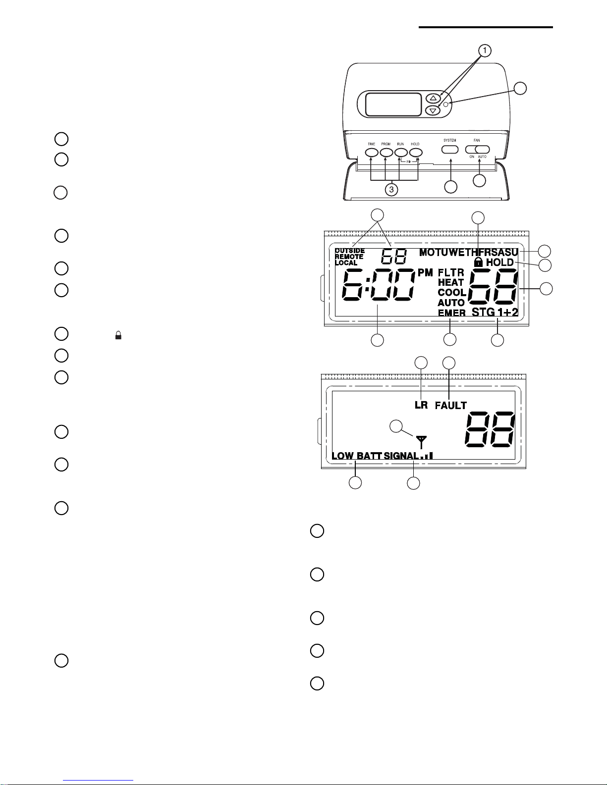
The configuration menu allows you to set certain thermostat
operating characteristics to your system or personal require-
ments.
Set SYSTEM button to OFFOFF
OFFOFF
OFF, then simultaneously press
and to enter configuration menu. The display will
show the first item in the configuration menu.
The configuration menu table summarizes the configuration
options. An explanation of each option follows.
Press SYSTEM to change to the next menu item. To exit the
menu and return to the program operation, pressRUN. If no
keys are pressed within fifteen minutes, the thermostat will
revert to normal operation.
1) Single Stage, Multi-stage or Heat Pump ConfigurationSingle Stage, Multi-stage or Heat Pump Configuration
Single Stage, Multi-stage or Heat Pump ConfigurationSingle Stage, Multi-stage or Heat Pump Configuration
Single Stage, Multi-stage or Heat Pump Configuration
This menu item requires you configure the thermostat to
match your system. Choose your system option from the
table below:
System TypeSystem Type
System Type Select OptionSelect Option
Select OptionSelect Option
Select Option
Single Stage Heat/Cool systems SS1
Multi-Stage Heat/Cool systems (No Heat Pump) MS2
Heat Pump system, 1 compressor or 1 speed compressor HP1
Heat Pump systems, 2 compressors or 2 speed compressor HP2
The thermostat is factory defaulted to MS2. To select a
different option, press the or key to scroll through
the choices.
THERMOSTTHERMOST
THERMOSTTHERMOST
THERMOSTAA
AA
AT CONFIGURAT CONFIGURA
T CONFIGURAT CONFIGURA
T CONFIGURATION MENUTION MENU
TION MENUTION MENU
TION MENU
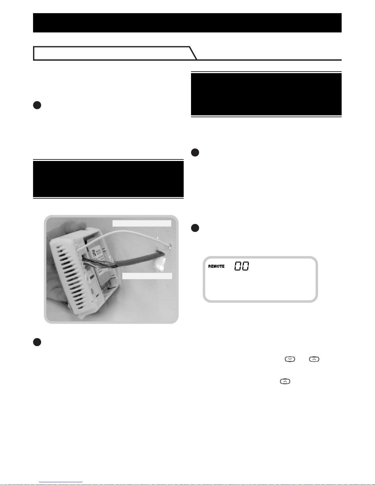
2) Select Learn Mode On or OffSelect Learn Mode On or Off
Select Learn Mode On or OffSelect Learn Mode On or Off
Select Learn Mode On or Off – Selecting LER OnLER On
LER OnLER On
LER On
enables the learn mode of the thermostat receiver. Your
thermostat is configured at the factory to recognize the
remote sensor shipped with it. The Learn Mode Option
is used only when required as described in Learn ModeLearn Mode
Learn ModeLearn Mode
Learn Mode
OptionOption
OptionOption
Option.
3) Selects OUTSIDE sensor OFF or ONSelects OUTSIDE sensor OFF or ON
Selects OUTSIDE sensor OFF or ONSelects OUTSIDE sensor OFF or ON
Selects OUTSIDE sensor OFF or ON – Selecting
OUTSIDE ON enables the thermostat to read a wireless
outdoor temperature sensor that has been configured
for Sensor O in the Learn Mode. This allows the thermo-
stat to display the outdoor temperature reading.
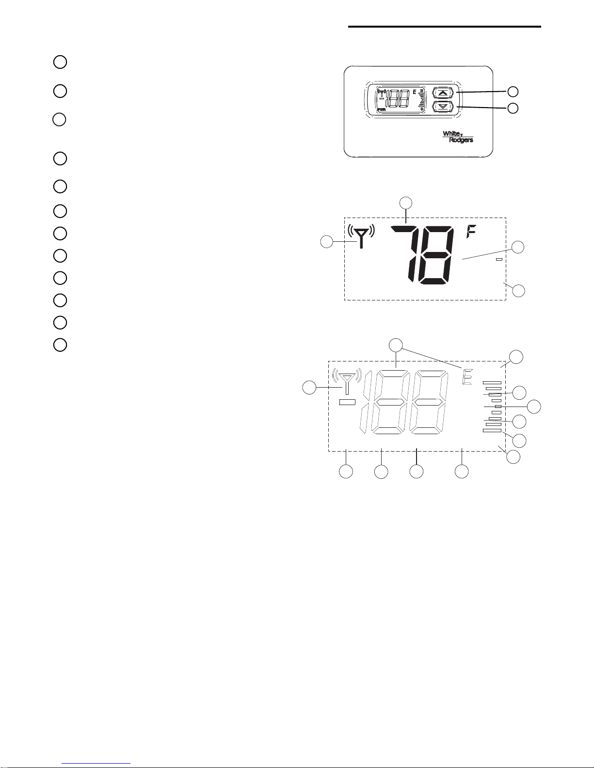
4) Selects REMOTE sensor OFF or ONSelects REMOTE sensor OFF or ON
Selects REMOTE sensor OFF or ONSelects REMOTE sensor OFF or ON
Selects REMOTE sensor OFF or ON – Selecting
REMOTE ON allows the thermostat to sense an indoor
remote sensor that has been set-up the Learn mode.
The maximum number of Indoor Remote Sensors is 1
configured to sensor A, B or C.
5) Selects LOCAL sensor ON or OFFSelects LOCAL sensor ON or OFF
Selects LOCAL sensor ON or OFFSelects LOCAL sensor ON or OFF
Selects LOCAL sensor ON or OFF – Appears if
Remote is set to ON. Selecting LOCAL ON allows the
thermostat to use the onboard temperature sensor
exclusively or for averaging with the remote sensor
readings. To control temperature using only the indoor
remote sensor temperature(s), use the
or
buttons
to select LOCAL OFFLOCAL OFF
LOCAL OFFLOCAL OFF
LOCAL OFF.
6) Select Receiver frequency offsetSelect Receiver frequency offset
Select Receiver frequency offsetSelect Receiver frequency offset
Select Receiver frequency offset – Appears if Remote is
set to ON. This option allows you to select a different
channel than the factory default for communication
between the thermostat and remote sensor. Note: If a
INSTALLER/CONFIGURATIONMENUINSTALLER/CONFIGURATIONMENU
INSTALLER/CONFIGURATIONMENU
Press the System button until OFFOFF
OFFOFF
OFF is displayed, then press the and simultaneously

11
14) Select Temperature Display Adjustment 4 LO to 4 HISelect Temperature Display Adjustment 4 LO to 4 HI
Select Temperature Display Adjustment 4 LO to 4 HISelect Temperature Display Adjustment 4 LO to 4 HI
Select Temperature Display Adjustment 4 LO to 4 HI –
Allows you to adjust the room temperature display up to
4° higher or lower. Your thermostat was accurately
calibrated at the factory but you have the option to
change the display temperature to match your previous
thermostat. The current or adjusted room temperature will
be displayed on the left side of the display.
15)Select Temporary Program Override TimeSelect Temporary Program Override Time
Select Temporary Program Override TimeSelect Temporary Program Override Time
Select Temporary Program Override Time–The thermo-
stat can hold any temperature you set it to for the amount
of time you select on this option. Your choices are 0:00 to
8:00 hours in 15 minute increments. 0:00 means disable.
Example:
1. You have selected 3:00 hours for the Temporary Pro-
gram Override time period.
2. With the thermostat set to Heat or Cool, press HOLD
for approximately 5 secondsfor approximately 5 seconds
for approximately 5 seconds until "HOLD time 3:00HOLD time 3:00
HOLD time 3:00HOLD time 3:00
HOLD time 3:00"
(indicating 3 hours) appears as a setting reminder.
3. After releasing the button, "HOLDHOLD
HOLDHOLD
HOLD"
on the display will
blink.
4. Use or to set the temperature to your prefer
ence. The thermostat will maintain this temperature
setting for 3 hours with "HOLDHOLD
HOLDHOLD
HOLD"
blinking to remind you
it is in Temporary Hold. After 3 hours, the thermostat
will go back to the program temperature and "HOLDHOLD
HOLDHOLD
HOLD"
will no longer blink or display.
16)Select F° or C° ReadoutSelect F° or C° Readout
Select F° or C° ReadoutSelect F° or C° Readout
Select F° or C° Readout – Changes the display readout
to Celsius or Fahrenheit as required.
17)Limited Heat RangeLimited Heat Range
Limited Heat RangeLimited Heat Range
Limited Heat Range – This feature provides a maximum
setpoint temperature for heat. The default setting is 90°F. It
can be changed between 62°F and 89°F by pressing the
or key.
18)Limited Cool RangeLimited Cool Range
Limited Cool RangeLimited Cool Range
Limited Cool Range – This feature provides a minimum
setpoint temperature for cool. The default setting is 45°F. It
can be changed between 46°F and 82°F by pressing the
or key.
19)Comfort AlertComfort Alert
Comfort AlertComfort Alert
Comfort Alert – This feature is available in Passive
mode on this thermostat. If a Comfort Alert module is
connected, the thermostat will receive and flash the fault
codes from the Comfort Alert module.
20 & 21) Keypad LockoutKeypad Lockout
Keypad LockoutKeypad Lockout
Keypad Lockout – This menu selection will
display locklock
locklock
lock ( ) icon. The and are used to toggle
the function and display the locklock
locklock
lock icon and OFFOFF
OFFOFF
OFF (keypad
not locked out, default) indicating in the time digits to the
locklock
locklock
lock icon and ONON
ONON
ON (keypad locked out). When the keypad
lockout function is enabled (ONON
ONON
ON), and the SYSTEM button
is pressed again, the display will indicate the number 000000
000000
000
(default, still disabled) in the time digits. The and
are used to set the combination number from 00
00
0 to 999999
999999
999. If
a combination of 000000
000000
000 is selected and the SYSTEM button
is pressed, the menu will be exited and keypad will not be
locked. If 1 to 9991 to 999
1 to 9991 to 999
1 to 999 is selected and the SYSTEM button is
pressed again, the combination is locked into non-volatile
memory and the menu is exited. The locklock
locklock
lock icon (to
designate keypad locked with a valid combination) will
display when the menu is exited. The SYSTEM button
will operate for 10 seconds after the menu mode is exited
to allow the user to change the mode from OFFOFF
OFFOFF
OFF to the
desired system mode.
While the keypad is locked out, a simultaneous press of
and will enter the menu item from any mode instead of
only OFFOFF
OFFOFF
OFF mode. When the menu is entered with the
keypad lockout feature enabled, the first menu item
displayed is the combination code 00
00
0. The or keys
are used to set the combination unlock number from 00
00
0 to
999999
999999
999. If the unlock number matches exactly with the
combination lock number stored in memory when the
SYSTEM button is pressed, the keypad is unlocked and
the locklock
locklock
lock icon is removed. If the unlock number does not
match when the SYSTEM
button is pressed, menu is
exited and the keypad remains disabled.
To reset the combination code and unlock the keypad if the
code is forgotten, see troubleshooting section, page 20.
different channel is selected on the thermostat it must also
be changed to the same setting on the remote. This is
only used in areas where there are other wireless
devices or electronic equipment that interfere with the
default frequency of the thermostat/remote sensor
communication.
7) Programmable PeriodsProgrammable Periods
Programmable PeriodsProgrammable Periods
Programmable Periods – This control can be config-
ured for 4, 2 or 0 programmable periods. The display
indicates "PRG 4PRG 4
PRG 4PRG 4
PRG 4" in the display as default. The program-
mable periods can be changed to 2 or 0 by pressing the
or keys. With "PRG 0PRG 0
PRG 0PRG 0
PRG 0" selected for non-program-
mable, SYSTEM key selection will skip EMREMR
EMREMR
EMR (item 8) and
temporary program override (item 15).
8) Select Energy Management Recovery OFF or ONSelect Energy Management Recovery OFF or ON
Select Energy Management Recovery OFF or ONSelect Energy Management Recovery OFF or ON
Select Energy Management Recovery OFF or ON –
Energy Management Recovery (EMR) causes the
thermostat to start heating or cooling early to make the
building temperature reach the program setpoint at the
time you specify. Heating will start 5 minutes early for
every 1° of temperature required to reach setpoint.
Example:Example:
Example:Example:
Example: You select EMR and have your heating
programmed to 65° at night and 70° at 7 AM. If the
building temperature is 65° the difference between 65°
and 70° is 5°. Allowing 5 minutes per degree the thermo-
stat setpoint will change to 70° at 6:35 AM. Cooling allows
more time per degree because it takes longer to reach
temperature.
9) Fast or Slow Cycle SelectionFast or Slow Cycle Selection
Fast or Slow Cycle SelectionFast or Slow Cycle Selection
Fast or Slow Cycle Selection – The factory default
setting is fast cycle, which cycles 1st stage at approxi-
mately 1.2°F and 2nd stage 0.75°F. If you prefer slow
cycle, press the temperature key to change to SL. The 1st
stage and 2nd stage would be 1.5°F and 1.2°F respec-
tively.
10)Select Compressor Lockout CL OFF or ONSelect Compressor Lockout CL OFF or ON
Select Compressor Lockout CL OFF or ONSelect Compressor Lockout CL OFF or ON
Select Compressor Lockout CL OFF or ON – Selecting
CL ON will cause the thermostat to wait 5 minutes before
turning on the compressor if the heating and cooling
system loses power. It will also wait 5 minutes minimum
between cooling and heating cycles. This is intended to
help protect the compressor from short cycling. Some
newer compressors already have a time delay built in and
do not require this feature. Your compressor manufac-
turer can tell you if the lockout feature is already present
in their system. When the thermostat compressor time
delay occurs it will flash the setpoint for about five
minutes.
11)Select Backlight DisplaySelect Backlight Display
Select Backlight DisplaySelect Backlight Display
Select Backlight Display – The display backlight improves
display contrast in low lighting conditions. When the "C"
terminal is powered, selecting backlight CdL ON will keep
the light on continuously. Select backlight OFF will keep
the light on momentarily after any key is pressed. When the
"C" terminal is not powered, the light will be on momen-
tarily after any key is pressed no matter the backlight is
selected ON or OFF.
12)Select Fast Second Stage On or OFFSelect Fast Second Stage On or OFF
Select Fast Second Stage On or OFFSelect Fast Second Stage On or OFF
Select Fast Second Stage On or OFF – For HeatFor Heat
For HeatFor Heat
For Heat:
During normal operation if the setpoint temperature is
manually raised by 3°F or more above the actual
temperature with the
button, and the fast second
stage feature is enabled, FA ON, the second stage will
energize immediately.
For Cool: During normal operation if the setpoint tem-
perature is manually lowered by 3°F or more below the
actual temperature with the button, and the fast
second stage feature is enabled, FA ON, the second
stage will energize immediately.
13)Select filter replacement run timeSelect filter replacement run time
Select filter replacement run timeSelect filter replacement run time
Select filter replacement run time – The thermostat will
display "FLTRFLTR
FLTRFLTR
FLTR"
after a set time of operation. This is a
reminder to change or clean your air filter. This time can be
set from 0 to 1950 hours in 50 hour increments. A selec-A selec-
A selec-A selec-
A selec-
tion of 0 will cancel this featuretion of 0 will cancel this feature
tion of 0 will cancel this feature. When "FLTRFLTR
FLTRFLTR
FLTR"
is
displayed, you can clear it by pressing HOLD and RUN at
the same time. This resets the timer and starts counting the
hours until the next filter change. Contact your system
manufacturer for a specific replacement/maintenance
interval.
THERMOSTTHERMOST
THERMOSTTHERMOST
THERMOSTAA
AA
AT CONFIGURAT CONFIGURA
T CONFIGURAT CONFIGURA
T CONFIGURATION MENUTION MENU
TION MENUTION MENU
TION MENU

12
REMOREMO
REMOREMO
REMOTE SENSOR CONFIGURATE SENSOR CONFIGURA
TE SENSOR CONFIGURATE SENSOR CONFIGURA
TE SENSOR CONFIGURATION MENUTION MENU
TION MENUTION MENU
TION MENU
The configuration menus allow you to set certain remote sensor operating characteristics to your system or personal require-
ments. Two configuration menus are available, User Configuration and Installer Configuration.
User Configuration MenuUser Configuration Menu
User Configuration Menu
Momentarily press and keys at the same time and release to enter the User menu. To scroll through the menu
items press the and keys at the same time. To change the item option press or . To exit the menu
scroll through all menu items. If no buttons are pushed for 3 minutes, the control will also return to normal operation.
The User Configuration Menu table summarizes the configuration options. An explanation of each option follows.
StepStep
StepStep
Step Pressbutton(s)Pressbutton(s)
Pressbutton(s)Pressbutton(s)
Pressbutton(s) DisplayedDisplayed
DisplayedDisplayed
Displayed PressPress
PressPress
Press oror
oror
or CommentsComments
CommentsComments
Comments
to scroll menuto scroll menu
to scroll menu (factory default)(factory default)
(factory default)(factory default)
(factory default) to change optionto change option
to change optionto change option
to change option
1 and LOCKLOCK
LOCKLOCK
LOCK on Select keypad lockout OFF or ON
(OF)
2 and HLDHLD
HLDHLD
HLD 1 to 8 hrs Select temporary adjust temperature
(4h) in 1 hour increments hold time
3 and CALIBCALIB
CALIBCALIB
CALIB 1-4 bars (1°-4°) C to Select temperature display adjustment
(Sensed Temperature) 1-4 bars (1°-4°) H higher or lower
4 and dFOF Select display temperature OFF or ON
(on)
5 and dL OF Select display backlight OFF or ON
(on)
6 and oFoC Select temperature display to F or C
(Sensed Temperature)
7 and _____ _____ Exits user menu and returns to normal
operation
User configuration menuUser configuration menu
User configuration menu
1) Select keypad lockout OFF or ONSelect keypad lockout OFF or ON
Select keypad lockout OFF or ONSelect keypad lockout OFF or ON
Select keypad lockout OFF or ON – Selecting LOCKLOCK
LOCKLOCK
LOCK
ONON
ONON
ON will cause the keypad to be locked in the normal
operation mode. This prevents the and from
being used to adjust temperature. The display will
indicate "LOCKLOCK
LOCKLOCK
LOCK" when the keypad is locked. If LOCK OFLOCK OF
LOCK OFLOCK OF
LOCK OF
is selected, the and keys can still be used.
When the keypad is locked, the and keys can
still be pressed at the same time to enter the configura-
tion menu.
2) Select temporary adjust temperature hold timeSelect temporary adjust temperature hold time
Select temporary adjust temperature hold timeSelect temporary adjust temperature hold time
Select temporary adjust temperature hold time –
Selects the length of time for the temporary temperature
adjustment. Hold time default is 4 hours and can be set
from 1 to 8 hours in 1 hour increments.
3) Select temperature display adjustment higher orSelect temperature display adjustment higher or
Select temperature display adjustment higher orSelect temperature display adjustment higher or
Select temperature display adjustment higher or
lowerlower
lowerlower
lower – allows you to adjust the room temperature
display 1° to 4° higher or lower. Your sensor was accu-
rately calibrated at the factory but you have the option to
change the display temperature to match your previous
sensor or thermostat.
4) Select display temperature OFF or ONSelect display temperature OFF or ON
Select display temperature OFF or ONSelect display temperature OFF or ON
Select display temperature OFF or ON – Selecting OFOF
OFOF
OF
allows you to disable displaying the sensed temperature.
Instead of the temperature, the sensor will display "PWRPWR
PWRPWR
PWR"
with the word onon
onon
on to indicate normal operation. With
display OFF the Transmitting icon will not appear.
5) Select display backlight OFF or ONSelect display backlight OFF or ON
Select display backlight OFF or ONSelect display backlight OFF or ON
Select display backlight OFF or ON -. The display
backlight improves display contrast in low lighting
conditions. Selecting dL ondL on
dL ondL on
dL on will keep the light on for a
short period of time after any key is pressed. Selecting
OFOF
OFOF
OF will keep the light off.
6) Select temperature display toSelect temperature display to
Select temperature display toSelect temperature display to
Select temperature display to oo
oo
oF orF or
F orF or
F or oo
oo
oCC
CC
C - Changes the
display readout to Celsius or Fahrenheit as required.

13
REMOREMO
REMOREMO
REMOTE SENSOR CONFIGURATE SENSOR CONFIGURA
TE SENSOR CONFIGURATE SENSOR CONFIGURA
TE SENSOR CONFIGURATION MENUTION MENU
TION MENUTION MENU
TION MENU
Installer Configuration MenuInstaller Configuration Menu
Installer Configuration Menu
Your thermostat is configured at the factory to recognize the remote sensor it is shipped with as indoor sensor A. The Installer
Configuration Menu is used only when adding or replacing a remote sensor or selecting a frequency offset.
Press and buttons at the same time for a minimum of five seconds then release to enter the Installer menu. To
scroll through the menu items, momentarily press the and buttons at the same time. To change the item option,
press or . To exit the menu scroll through all menu items. If no buttons are pushed for 3 minutes, the control will
return to normal operation. The Installer Configuration Menu table summarizes the configuration options. An explanation of
each option follows.
StepStep
StepStep
Step Pressbutton(s)Pressbutton(s)
Pressbutton(s)Pressbutton(s)
Pressbutton(s) DisplayedDisplayed
DisplayedDisplayed
Displayed PressPress
PressPress
Press oror
oror
or CommentsComments
CommentsComments
Comments
to scroll menuto scroll menu
to scroll menu (factory default)(factory default)
(factory default)(factory default)
(factory default) to change optionsto change options
to change optionsto change options
to change options
1 and LEARNLEARN
LEARNLEARN
LEARN on Select learn mode OFF or ON
(OF)
2 and CHCH
CHCH
CH B,C, O Select sensor identification as A, B, C or O
(A)
3 and CC
CC
C 1 through 9 Select transmitter frequency offset
(0)
4 and _____ _____ Exit installer menu and return to normal
operation
Installer Configuration MenuInstaller Configuration Menu
Installer Configuration Menu
1) Select learn mode OFF or ONSelect learn mode OFF or ON
Select learn mode OFF or ONSelect learn mode OFF or ON
Select learn mode OFF or ON – Selecting LEARN onLEARN on
LEARN onLEARN on
LEARN on
enables the sensors learning mode. In the learning mode
the sensor will transmit identification information once
every 10 seconds for a period of 10 minutes. The LEARN
icon will be displayed during the learning mode. The
Transmitting icon will be displayed for a short period of
time with each transmission. See Learn Mode Option.
If the display is selected OFF, the Transmit icon and
Learn icon will not appear.
2) Select sensor identification from A to OSelect sensor identification from A to O
Select sensor identification from A to OSelect sensor identification from A to O
Select sensor identification from A to O – For multiple
sensors systems, each sensor must have a designated
identification. The thermostat can operate with one indoor
sensor and one outdoor sensor. For indoor sensors you
may select A, B or C. For outdoor sensor you must select
O.
3) Select transmitter frequency offsetSelect transmitter frequency offset
Select transmitter frequency offsetSelect transmitter frequency offset
Select transmitter frequency offset – The sensor’s
transmitter operates on 418MHz radio frequency by
default. Interference may occur if another device or
equipment operates on the same frequency. The interfer-
ence may degrade the communications between the
sensor and the thermostat. To avoid interference, you
may select a different radio frequency for your sensor.
This menu item allows you to select a radio frequency
offset from 1 to 9MHz from the base frequency. For
example; if you selected an offset of 4, the transmitter
radio frequency will be 418MHz + 4MHz = 422MHz. Note
that the sensor’s transmitter and the thermostat’s receiver
must operate on the same frequency to communicate. To
change thermostat’s receiver frequency please refer to
Thermostat Configuration Menu (Item 6).
OPERATINGYOURTHERMOSTATANDREMOTESENSOROPERATINGYOURTHERMOSTATANDREMOTESENSOR
OPERATINGYOURTHERMOSTATANDREMOTESENSOR
NOTE
Check Thermostat OperationCheck Thermostat Operation
Check Thermostat Operation
To prevent static discharge problems, touch side ofTo prevent static discharge problems, touch side of
To prevent static discharge problems, touch side of
thermostat to release static build-up before touchingthermostat to release static build-up before touching
thermostat to release static build-up before touching
any keys.any keys.
any keys.any keys.
any keys.
Donotallowthecompressortorununlessthecompres-Donotallowthecompressortorununlessthecompres-
Donotallowthecompressortorununlessthecompres-
sor oil heaters have been operational for 6 hours andsor oil heaters have been operational for 6 hours and
sor oil heaters have been operational for 6 hours and
the system has not been operational for at least 5the system has not been operational for at least 5
the system has not been operational for at least 5
minutes.minutes.
minutes.minutes.
minutes.
CAUTION
!
If at any time during testing your system does not operate
properly, contact a qualified service person.
Fan OperationFan Operation
Fan Operation
If your system does not have a GG
GG
G terminal connection, skip to
Heating SystemHeating System
Heating System.
1. Turn on power to system.
2. Move FAN switch to ONON
ONON
ON position. The blower should
begin to operate.
3. Move FAN switch to AUTOAUTO
AUTOAUTO
AUTO position. The blower should
stop immediately.
Heating SystemHeating System
Heating System
1. Press SYSTEM button to select HEATHEAT
HEATHEAT
HEAT. If the auxiliary
heating system has a standing pilot, be sure to light it.
2. Press to adjust thermostat setting to 1° above room
temperature. The heat pump system should begin to
operate. The display should show "STG1STG1
STG1STG1
STG1". However, if the
system configuration is set to HP1 or HP2 and setpoint
temperature display is flashing, the 5 minute compressor
lockout feature is operating (see Configuration menu,
item 10).
3. Adjust temperature setting to 3° above room temperature.
If your system configuration is set at MS2, HP2 or HP1,
the auxiliary heat system should begin to operate and
the display will show "STG 1+2STG 1+2
STG 1+2STG 1+2
STG 1+2".
4. Press to adjust the thermostat below room tempera-
ture. The heating system should stop operating.

14
CAUTION
!
Emergency SystemEmergency System
Emergency System
EMEREMER
EMEREMER
EMER bypasses the Heat Pump to use the heat source wired
to terminal E/W1E/W1
E/W1E/W1
E/W1 on the thermostat. EMEREMER
EMEREMER
EMER is typically used
when compressor operation is not desired, or you prefer
back-up heat only.
1. Press SYSTEM button to select EMEREMER
EMEREMER
EMER. "EMEREMER
EMEREMER
EMER" will flash
on the display.
2. Press to adjust thermostat setting above room
temperature. The Emergency heating system will begin to
operate. The display will show "STG1STG1
STG1STG1
STG1" flashing "EMEREMER
EMEREMER
EMER"
and "HEATHEAT
HEATHEAT
HEAT" to indicate that the Emergency system is
operating.
3. Press to adjust the thermostat below room tempera-
ture. The Emergency heating system should stop operat-
ing.
To prevent compressor and/or property damage, if theTo prevent compressor and/or property damage, if the
To prevent compressor and/or property damage, if the
outdoor temperature is below 50°F, DO NOT operateoutdoor temperature is below 50°F, DO NOT operate
outdoor temperature is below 50°F, DO NOT operate
the cooling system.the cooling system.
the cooling system.
Cooling SystemCooling System
Cooling System
1. Press SYSTEM button to select COOLCOOL
COOLCOOL
COOL.
2. Press to adjust thermostat setting below room
temperature. The blower should come on immediately on
high speed, followed by cold air circulation. The display
should show "STG1STG1
STG1STG1
STG1". If the setpoint temperature display
is flashing, the compressor lockout feature is operating
(see Configuration menu, item 5).
3. Adjust temperature setting to 3° below room temperature.
The second stage cooling should begin to operate and
the display should show "STG 1+2STG 1+2
STG 1+2STG 1+2
STG 1+2".
4. Press to adjust the temperature setting above room
temperature. The cooling system should stop operating.
Remote Temperature Sensor InformationRemote Temperature Sensor Information
Remote Temperature Sensor Information
on the Thermostat Displayon the Thermostat Display
on the Thermostat Display
During normal operation, the upper left of the thermostat
display changes every 6 seconds to show the temperatures
at the sensors that are turned on in the configuration menu.
The sensors are the thermostat (LOCALLOCAL
LOCALLOCAL
LOCAL), the outdoor
remote sensor (OUTDOOROUTDOOR
OUTDOOROUTDOOR
OUTDOOR) and the indoor remote sensor
(REMOTEREMOTE
REMOTEREMOTE
REMOTE). Below that, the display alternately shows the
time and temperature average of the sensors that are turned
on.
The word "SIGNALSIGNAL
SIGNALSIGNAL
SIGNAL"
is shown along with number of bars (1-
3) indicating the relative signal strength. More bars mean
better reception. The antennaantenna
antennaantenna
antenna icon also displays for few
seconds when information from the remote sensor is
received.
If the thermostat does not receive an update signal from an
enabled remote sensor (REMOTE or OUTDOOR) for 30
minutes or more, the thermostat will display FAULT and
ANTENNA icons continuously. The REMOTE or OUTDOOR
sensor that has communication with the thermostat inter-
rupted will display a temperature of 00. If the active sensor is
the REMOTE, the thermostat will revert back to LOCAL
sense only mode.
OPERATINGYOURTHERMOSTATANDREMOTESENSOROPERATINGYOURTHERMOSTATANDREMOTESENSOR
OPERATINGYOURTHERMOSTATANDREMOTESENSOR
Automatic System ChangeoverAutomatic System Changeover
Automatic System Changeover
When the thermostat is in the AUTOAUTO
AUTOAUTO
AUTO mode, the thermostat
will call for heat or cool depending on the room temperature.
The setpoint temperature displayed will be the last mode
called. If the last system cycle was heat, the HEATHEAT
HEATHEAT
HEAT setpoint
will be displayed. If the room temperature raises above the
HEATHEAT
HEATHEAT
HEAT setpoint and the COOLCOOL
COOLCOOL
COOL setpoint and a call for cool is
required, the temperature displayed will change to be the
COOLCOOL
COOLCOOL
COOL setpoint.
If you manually override the temperature in AUTOAUTO
AUTOAUTO
AUTO and it
does not switch to the mode (HEATHEAT
HEATHEAT
HEAT or COOLCOOL
COOLCOOL
COOL) that you want,
press the and keys once, at the same time to switch
modes. At the end of your override time it will revert back to
AUTO.
Second Stage Time DelaySecond Stage Time Delay
Second Stage Time Delay
Your thermostat is designed to determine the optimum time
to activate the second stage. Simply raising the temperature
in heating or lowering it in cooling will not always force the
thermostat to bring the second stage on quickly. If the fast
second stage option in the configuration menu (step 12) is
set to "OFF", there is a delay from 0-30 minutes depending
on the performance of the first stage of the system.
EXAMPLE: For the last 2 hours the thermostat is set on 70°
and the room temperature is 70° with the equipment using
only the first stage of heat. Since the equipment is keeping
the temperature within 1 degree of setpoint, the thermostat
will delay second stage for a longer time if you manually
raise the temperature or if the room temperature quickly
changes. Once the second stage comes on, it will come on
sooner the next time there is a difference between the
setpoint and the room temperature. The net effect of the
staging program is that when the first stage is capable of
holding temperature, the second stage will delay longer.
When the thermostat calculates that first stage cannot make
temperature in a reasonable time, the second stage will
come on sooner. This built in function automatically opti-
mizes the use of additional stages of heat or cool.
LearLear
LearLear
Learn Mode Optionn Mode Option
n Mode Optionn Mode Option
n Mode Option
Your thermostat is configured at the factory to recognize the
wireless remote sensor shipped with it. This sensor is stored
as Sensor A. The Learn Mode Option must be performed on
the thermostat and wireless remote sensor if:
• A wireless remote sensor is added to another channel.
• The wireless remote sensor is replaced.
• The thermostat is replaced.
• The thermostat has been reset using ,,
,,
, ,,
,,
, and
SYSTEM keys.
During the Learn Mode, the wireless remote sensor will
transmit identification information every ten seconds for ten
minutes. In this ten-minute period, the display will show
“LEARN” and the antenna icon will show for a short time with
each transmission. The thermostat will be receiving the
transmitted identification information.
To perform the Learn Mode on the thermostat and sensor:
Remove the batteries from all wireless remote sensors in
the same building except the sensor you are going to put
into the Learn Mode. This will prevent interference from
the other sensors.
Be sure that the remote sensor is set for the proper

15
OPERATINGYOURTHERMOSTATANDREMOTESENSOROPERATINGYOURTHERMOSTATANDREMOTESENSOR
OPERATINGYOURTHERMOSTATANDREMOTESENSOR
identification (A, B or C for indoor or O for outdoor) and
the thermostat and remote sensor are set to the same
frequency.
On the thermostat, enter the thermostat Configuration
Menu by pressing the SYSTEMSYSTEM
SYSTEMSYSTEM
SYSTEM button to OFFOFF
OFFOFF
OFF and then
momentarily pressing
and at the same time.
Momentarily press SYSTEMSYSTEM
SYSTEMSYSTEM
SYSTEM button to advance to step 2
of the Configuration Menu. The display will show “LER”“LER”
“LER”“LER”
“LER”
and “OFF”“OFF”
“OFF”“OFF”
“OFF”.
Momentarily press
or to select “LER”“LER”
“LER”“LER”
“LER” and “On”“On”
“On”“On”
“On”.
The display will flash “LER”“LER”
“LER”“LER”
“LER” with “On”“On”
“On”“On”
“On” displayed con-
stantly.
On the wireless remote sensor, enter the Installer
Configuration Menu by pressing
and for five
seconds. The remote sensor display will change to
“LEARN OFF”“LEARN OFF”
“LEARN OFF”.
Momentarily press
or to select “LEARN On”“LEARN On”
“LEARN On”“LEARN On”
“LEARN On”.
Exit the menu. The sensor will begin the Learn mode.
After the thermostat has successfully identified the
remote sensor in approximately one minute, the sensor
information will be stored and the thermostat display will
change to “LER”“LER”
“LER”“LER”
“LER” and “OK”“OK”
“OK”“OK”
“OK”.
If the identification sequence is not successful after ten
minutes, the thermostat display will show “LER”,“LER”,
“LER”,“LER”,
“LER”, “Fault”“Fault”
“Fault”“Fault”
“Fault” and
the antenna icon. If the Learn Mode is unsuccessful, refer to
Troubleshooting section, Antenna + Fault.
If you are replacing a thermostat that has more than one
wireless remote sensor, the Learn Mode must be performed
for each sensor. Once a sensor has been identified, it will
remain in the thermostat memory until the Learn Mode is
performed again and a different sensor for the stored
channel is identified.
Wireless Remote IndoorWireless Remote Indoor
Wireless Remote Indoor
TemperatureAveragingTemperatureAveraging
TemperatureAveraging
Your thermostat is designed to sense the temperature of
the indoor remote sensor and average or weight it with the
local sensor in the thermostat for each program period. The
averaging will only be active when both the local and the
indoor remote sensors are functional and turned on in the
configuration menu. When the thermostat is placed in view
schedule mode (press PRGM once), the weight of the
indoor remote sensor will be shown on the left side of the
display when HOLD button is pressed. The weighting
classes of the indoor remote sensor are designated as A
(default for average weight), HI (high weight), or LO (low
weight). The HI weight is two times the weight of the average
weight. The Aweight is two times the weight of the LO
weight. The weight of the local sensor is fixed to A(average
weight). The actual temperature displayed, in the clock
digits, in the normal operation mode is the mathematical
weighted sum of the enabled functioning sensors. For
example, if the local sensed temperature is 80°F and the
remote sensed temperature is 70°F then:
If weight selected is HI , then the averaged temperature is
(2 x (80°F) + 4 x (70°F))/ 6 = 73.3°F.
If weight selected is A, then the averaged temperature is
(2 x (80°F) + 2 x (70°F))/ 4 = 75°F.
If weight selected is LO , then the averaged temperature is
(2 x (80°F) + 1 x (70°F))/ 3 = 76.6°F.
The example above shows that the weight selected would
prioritize the overall averaged temperature between the two
sensors. The high weight selection caused the remote
sensor to carry more weight in the calculated temperature
average than the local sensor. The low weight selection
caused the remote sensor to carry less weight in the
calculated temperature average than the local sensor.
Choose the FChoose the F
Choose the Fan Setting (Aan Setting (A
an Setting (Aan Setting (A
an Setting (Auto or On)uto or On)
uto or On)uto or On)
uto or On)
Set the FAN Switch to AA
AA
Autouto
utouto
uto or OnOn
OnOn
On.
Fan AutoAuto
AutoAuto
Auto is the most commonly selected setting and runs
the fan only when the heating or cooling system is on.
Fan OnOn
OnOn
On runs the fan continuously for increased air circula-
tion or to allow additional air cleaning.
Choose the System SettingChoose the System Setting
Choose the System Setting
(Hea(Hea
(Hea(Hea
(Heat,t,
t,t,
t, OfOf
OfOf
Offf
ff
f,,
,,
,Cool,Cool,
Cool,Cool,
Cool,
AA
AA
Autouto
utouto
uto,,
,,
,Emer)Emer)
Emer)Emer)
Emer)
Press the SYSTEM button to select:
HeatHeat
HeatHeat
Heat: Thermostat controls only the heating system.
OfOf
OfOf
Offf
ff
f: Heating and Cooling systems are off.
CoolCool
CoolCool
Cool: Thermostat controls only the cooling system.
AutoAuto
AutoAuto
Auto: Auto Changeover is used in areas where both heating
and cooling may be required on the same day. AA
AA
AUTUT
UTUT
UTOO
OO
O allows
the thermostat to automatically select heating or cooling
depending on the indoor temperature and the selected heat
and cool temperatures. When using AA
AA
AUTUT
UTUT
UTOO
OO
O, be sure to set the
Cooling temperatures more than 1° Fahrenheit higher than
the heating temperature.
EmerEmer
EmerEmer
Emer: Setting is available only when the thermostat is
configured in HP1 or HP2 mode.
Manual Operation forManual Operation for
Manual Operation for
Non-PrNon-Pr
Non-PrNon-Pr
Non-Proo
oo
ogg
gg
grr
rr
rammaamma
ammaamma
ammabb
bb
blele
lele
le TT
TT
Therher
herher
hermostamosta
mostamosta
mostatsts
tsts
ts
Press the SYSTEM button to select Heat or Cool and use
the
or buttons to adjust the temperature to your
desired setting. After selecting your desired settings you can
also press the SYSTEM button to select AUTOAUTO
AUTOAUTO
AUTO to allow
the thermostat to automatically change between Heat and
Cool.
Manual Operation (Bypassing the Program)Manual Operation (Bypassing the Program)
Manual Operation (Bypassing the Program)
Programmable ThermostatsProgrammable Thermostats
Programmable Thermostats
Press or and adjust the temperature wherever you
like. Then press HOLD. This will override the program. The
HOLDHOLD
HOLDHOLD
HOLD feature bypasses the program and allows you to
adjust the temperature manually, as needed. Whatever
temperature you set in HOLDHOLD
HOLDHOLD
HOLD will be maintained 24 hours a
day, until you manually change the temperature or press
RUN to cancel HOLDHOLD
HOLDHOLD
HOLD and resume the programmed sched-
ule.
PrPr
PrPr
Proo
oo
ogg
gg
grr
rr
ram Ovam Ov
am Ovam Ov
am Overer
erer
erride (Tride (T
ride (Tride (T
ride (Temporempor
emporempor
emporarar
arar
ary Ovy Ov
y Ovy Ov
y Overer
erer
erride)ride)
ride)ride)
ride)
Press or buttons to adjust the temperature. This will
override the temperature setting for a (default) four hour
override period. The override period can be shortened or
lengthened by adjusting the temporary hold time in the
configuration menu.
ExampleExample
ExampleExample
Example: If you turn up the heat during the morning pro-
gram, it will be automatically lowered later, when the
temporary hold period ends. To cancel the temporary setting
at any time and return to the program, press RUN.
If the SYSTEM button is pressed to select AUTOAUTO
AUTOAUTO
AUTO the
thermostat will change to Heat or Cool, whichever ran last. If
it switches to heat but you want cool, or it changes to cool
but you want heat, press both
and buttons simulta-
neously to change to the other mode.

16
PROGRAMMINGYOURTHERMOSTATPROGRAMMINGYOURTHERMOSTAT
PROGRAMMINGYOURTHERMOSTAT
This section will help you plan your thermostat's program to
meet your needs. For maximum comfort and efficiency, keep
the following guidelines in mind when planning your program.
• When heating (cooling) your building, program the temper-
atures to be cooler (warmer) when the building is vacant or
during periods of low activity.
• During early morning hours, the need for cooling is usually
minimal. Planning Your ProgramPlanning Your Program
Planning Your ProgramPlanning Your Program
Planning Your Program
Look at the factory preprogrammed times and temperatures
shown in the sample schedule. If this program will suit your
needs, simply set the time and day and press the RUN
button to begin running the factory preset program.
If you want to change the preprogrammed times and tem-
peratures, follow these steps.
Determine the time periods and temperatures for your
program. You must program four periods for each day.
However, you may use the same heating and cooling
temperatures for consecutive time periods. You can choose
start times, heating temperatures, and cooling temperatures
independently (for example, you may select 5:00 AM and 70°
as the weekday 1st period heating1st period heating
1st period heating1st period heating
1st period heating start time and tempera-
ture and also choose 7:00 AM and 76° as the weekday 1st1st
1st1st
1st
period coolingperiod cooling
period cooling start time and temperature).
Use the table to plan your program time periods and the
temperatures you want during each period. Fill in the
complete table to have a record of your programs.
PERIODPERIOD
PERIODPERIOD
PERIOD WEEKDAYS(5DAYS)WEEKDAYS(5DAYS)
WEEKDAYS(5DAYS)WEEKDAYS(5DAYS)
WEEKDAYS(5DAYS) SATURDAY(1DAY)SATURDAY(1DAY)
SATURDAY(1DAY)SATURDAY(1DAY)
SATURDAY(1DAY) SUNDAY(1DAY)SUNDAY(1DAY)
SUNDAY(1DAY)SUNDAY(1DAY)
SUNDAY(1DAY)
STARTSTART
STARTSTART
START REMOTEREMOTE
REMOTEREMOTE
REMOTE STARTSTART
STARTSTART
START REMOTEREMOTE
REMOTEREMOTE
REMOTE STARTSTART
STARTSTART
START REMOTEREMOTE
REMOTEREMOTE
REMOTE
TIMETIME
TIMETIME
TIME TEMPTEMP
TEMPTEMP
TEMP WEIGHTWEIGHT
WEIGHTWEIGHT
WEIGHT TIMETIME
TIMETIME
TIME TEMPTEMP
TEMPTEMP
TEMP WEIGHTWEIGHT
WEIGHTWEIGHT
WEIGHT TIMETIME
TIMETIME
TIME TEMPTEMP
TEMPTEMP
TEMP WEIGHTWEIGHT
WEIGHTWEIGHT
WEIGHT
MORNMORN
MORNMORN
MORN 6:00 AM6:00 AM
6:00 AM6:00 AM
6:00 AM 70 F70 F
70 F70 F
70 F AA
AA
A6:00 AM6:00 AM
6:00 AM6:00 AM
6:00 AM 70 F70 F
70 F70 F
70 F AA
AA
A6:00 AM6:00 AM
6:00 AM6:00 AM
6:00 AM 70 F70 F
70 F70 F
70 F AA
AA
A
DAYDAY
DAYDAY
DAY 8:00 AM8:00 AM
8:00 AM8:00 AM
8:00 AM 62 F62 F
62 F62 F
62 F AA
AA
A8:00 AM8:00 AM
8:00 AM8:00 AM
8:00 AM 62 F62 F
62 F62 F
62 F AA
AA
A8:00 AM8:00 AM
8:00 AM8:00 AM
8:00 AM 62 F62 F
62 F62 F
62 F AA
AA
A
EVEEVE
EVEEVE
EVE 5:00 PM5:00 PM
5:00 PM5:00 PM
5:00 PM 70 F70 F
70 F70 F
70 F AA
AA
A5:00 PM5:00 PM
5:00 PM5:00 PM
5:00 PM 70 F70 F
70 F70 F
70 F AA
AA
A5:00 PM5:00 PM
5:00 PM5:00 PM
5:00 PM 70 F70 F
70 F70 F
70 F AA
AA
A
NITENITE
NITENITE
NITE 10:00 PM10:00 PM
10:00 PM10:00 PM
10:00 PM 62 F62 F
62 F62 F
62 F AA
AA
A10:00 PM10:00 PM
10:00 PM10:00 PM
10:00 PM 62 F62 F
62 F62 F
62 F AA
AA
A10:00 PM10:00 PM
10:00 PM10:00 PM
10:00 PM 62 F62 F
62 F62 F
62 F AA
AA
A
MORNMORN
MORNMORN
MORN 6:00 AM6:00 AM
6:00 AM6:00 AM
6:00 AM 78 F78 F
78 F78 F
78 F AA
AA
A6:00 AM6:00 AM
6:00 AM6:00 AM
6:00 AM 78 F78 F
78 F78 F
78 F AA
AA
A6:00 AM6:00 AM
6:00 AM6:00 AM
6:00 AM 78 F78 F
78 F78 F
78 F AA
AA
A
DAYDAY
DAYDAY
DAY 8:00 AM8:00 AM
8:00 AM8:00 AM
8:00 AM 85 F85 F
85 F85 F
85 F AA
AA
A8:00 AM8:00 AM
8:00 AM8:00 AM
8:00 AM 85 F85 F
85 F85 F
85 F AA
AA
A8:00 AM8:00 AM
8:00 AM8:00 AM
8:00 AM 85 F85 F
85 F85 F
85 F AA
AA
A
EVEEVE
EVEEVE
EVE 5:00 PM5:00 PM
5:00 PM5:00 PM
5:00 PM 78 F78 F
78 F78 F
78 F AA
AA
A5:00 PM5:00 PM
5:00 PM5:00 PM
5:00 PM 78 F78 F
78 F78 F
78 F AA
AA
A5:00 PM5:00 PM
5:00 PM5:00 PM
5:00 PM 78 F78 F
78 F78 F
78 F AA
AA
A
NITENITE
NITENITE
NITE 10:00 PM10:00 PM
10:00 PM10:00 PM
10:00 PM 82 F82 F
82 F82 F
82 F AA
AA
A10:00 PM10:00 PM
10:00 PM10:00 PM
10:00 PM 82 F82 F
82 F82 F
82 F AA
AA
A10:00 PM10:00 PM
10:00 PM10:00 PM
10:00 PM 82 F82 F
82 F82 F
82 F AA
AA
A
OPERATINGYOURTHERMOSTATANDREMOTESENSOROPERATINGYOURTHERMOSTATANDREMOTESENSOR
OPERATINGYOURTHERMOSTATANDREMOTESENSOR
FACTORYPROGRAMFACTORYPROGRAM
FACTORYPROGRAM
PERIODPERIOD
PERIODPERIOD
PERIOD WEEKDAYS(5DAYS)WEEKDAYS(5DAYS)
WEEKDAYS(5DAYS)WEEKDAYS(5DAYS)
WEEKDAYS(5DAYS) SATURDAY(1DAY)SATURDAY(1DAY)
SATURDAY(1DAY)SATURDAY(1DAY)
SATURDAY(1DAY) SUNDAY(1DAY)SUNDAY(1DAY)
SUNDAY(1DAY)SUNDAY(1DAY)
SUNDAY(1DAY)
STARTSTART
STARTSTART
START REMOTEREMOTE
REMOTEREMOTE
REMOTE STARTSTART
STARTSTART
START REMOTEREMOTE
REMOTEREMOTE
REMOTE STARTSTART
STARTSTART
START REMOTEREMOTE
REMOTEREMOTE
REMOTE
TIMETIME
TIMETIME
TIME TEMPTEMP
TEMPTEMP
TEMP WEIGHTWEIGHT
WEIGHTWEIGHT
WEIGHT TIMETIME
TIMETIME
TIME TEMPTEMP
TEMPTEMP
TEMP WEIGHTWEIGHT
WEIGHTWEIGHT
WEIGHT TIMETIME
TIMETIME
TIME TEMPTEMP
TEMPTEMP
TEMP WEIGHTWEIGHT
WEIGHTWEIGHT
WEIGHT
MORNMORN
MORNMORN
MORN
DAYDAY
DAYDAY
DAY
EVEEVE
EVEEVE
EVE
NITENITE
NITENITE
NITE
MORNMORN
MORNMORN
MORN
DAYDAY
DAYDAY
DAY
EVEEVE
EVEEVE
EVE
NITENITE
NITENITE
NITE
PERSONALPROGRAMPERSONALPROGRAM
PERSONALPROGRAM
COOLCOOL
COOLCOOL
COOL HEATHEAT
HEATHEAT
HEAT COOLCOOL
COOLCOOL
COOL HEATHEAT
HEATHEAT
HEAT
Description Remote Sensor Thermostat Display (Remote) Thermostat Display (Local) Calculated Room Temp. Setpoint Temp.
Increasing setting decreases room H +4 bars Decreases by 4°F to 71°F 73°F
temperature average causing system H +3 bars Decreases by 3°F to 72°F 73.5°F
to increase temperature. H +2 bars Decreases by 2°F to 73°F 74°F
H +1 bar Decreases by 1°F to 74°F 74.5°F
Remote 75°F 75°F 75° 75°F
Decreasing setting increases room C -1 bar Increases by 1°F to 76°F 75.5°F
temperature causing more of a C -2 bars Increases by 2°F to 77°F 76°F
demand for Cooling. C -3 bars Increases by 3°F to 78°F 76.5°F
C -4 bars Increases by 4°F to 79°F 77°F
Remote Sensor OperationRemote Sensor Operation
Remote Sensor Operation
The sensor monitors the temperature and sends information
to the thermostat. Updated information is sent to the thermo-
stat when the temperature changes 3/16 degree or more
from the last update. If the temperature does not change for
10 minutes, the sensor will transmit to assure communica-
tion.
Low Battery powerLow Battery power
Low Battery power: The sensor will display the word LOLO
LOLO
LO
along with BATTBATT
BATTBATT
BATT icon to indicate a low battery power
condition. The 2 "AAA" batteries must be replaced to ensure
a proper sensor performance. For optimum performance,
replace batteries once a year with new premium brand
alkaline batteries such as Duracell®or Energizer®.
Increasing the sensor Comfort graph toward H decreases
the displayed remote temperature shown on the thermostat
by 1°F per bar. This will lower the actual calculated room
temperature by up to 4°F. Decreasing the sensor Comfort
graph toward C increases the displayed remote temperature
and will raise the actual calculated room temperature. The
table below shows how the adjustment on the sensor affects
the displayed remote temperature on the thermostat and the
calculated average temperature.

PROGRAMMINGPROGRAMMING
PROGRAMMING
Enter Heating ProgramEnter Heating Program
Enter Heating Program
1. Press the SYSTEM button to HEATHEAT
HEATHEAT
HEAT.
2. Press PRGM once. "MO TU WE TH FRMO TU WE TH FR
MO TU WE TH FRMO TU WE TH FR
MO TU WE TH FR" (indicating
weekday program) will appear in the display. Also dis-
played are the currently programmed start time for the
1st heating period and the currently programmed temp-
erature (flashing).
EXAMPLE:
This display window shows that for the 1st weekday
period, the start time is 6:00 AM and 68° is the program-
med temperature (this example reflects factory prepro-
gramming.
3. Press or to change the displayed temperature
to your selected temperature for the 1st heating program
period.
4. Press TIME once (the programmed time will flash). Press
or until your selected time appears. The time
will change in 15 minute increments. When your selected
time is displayed, press TIME again to return to the
change temperature mode.
5. If both the local and the remote sensors are enabled, then
you may press HOLD button to change the remote sensor
Setting the Clock and DaySetting the Clock and Day
Setting the Clock and Day
Remove the battery tag from the thermostat.
Set Current Time and DaySet Current Time and Day
Set Current Time and Day
1. Press TIME button once. The display will show the hour
only.
EXAMPLE:
2. Press and hold either or until you reach the
correct hour and AM/PM designation (AMAM
AMAM
AM begins at mid-
night; PMPM
PMPM
PM begins at noon). AA
AA
A will indicate for AM. PP
PP
P will
indicate for PM in the minutes digits.
3. Press TIME once again. The display window will show
the minutes only.
EXAMPLE:
4. Press and hold either or until you reach the
correct minutes.
5. Press TIME once again. The display will show the day of
the week.
6. Press or until you reach the current day of the
week.
7. Press RUN once. The display will show the correct time
and room temperature alternately.
This thermostat starts the programmed temperature earlier
than the time selected in your program. This allows the
system to reach your setting by the time you specify in your
program. This feature is called EMR (Energy Management
Recovery). If you do not want the thermostat to start early,
you may cancel the EMR feature in the Configuration Menu.
17
weighting setting. Remote icon will display. The pro-
grammed weight (A, HI or LO) will flash. Press or
to change the displayed weight to your selected weight
for the 1st heat program period.
CHECKYOURPROGRAMMINGCHECKYOURPROGRAMMING
CHECKYOURPROGRAMMING
Follow these steps to check your thermostat programming
one final time before beginning thermostat operation.
1. Press SYSTEM button to HEATHEAT
HEATHEAT
HEAT position.
2. Press PRGM to view the 1st weekday heating period
time and temperature. Each time you press PRGM, the
next heating period time and temperature will be display-
ed in sequence for weekday, then Saturday and Sunday
program periods (you may change any time or tempera-
ture during this procedure.
3. Press RUN.
4. Press SYSTEM button to COOLCOOL
COOLCOOL
COOL position.
5. Repeat step 2 to check cooling program.
6. Press SYSTEM button to HEATHEAT
HEATHEAT
HEAT or COOLCOOL
COOLCOOL
COOL and press
RUN to begin program operation.
NOTE: Batteries are not required to keep your programming
or menu data. With two optional "AA" batteries installed,
your thermostat will maintain time and continuously
display the temperature during a loss of AC power.
Installed batteries will also allow programming prior to
installation.
YOUR THERMOSTAT IS NOW PROGRAMMED AND READY TOYOUR THERMOSTAT IS NOW PROGRAMMED AND READY TO
YOUR THERMOSTAT IS NOW PROGRAMMED AND READY TO
PROVIDEMAXIMUMCOMFORTANDEFFICIENCY!PROVIDEMAXIMUMCOMFORTANDEFFICIENCY!
PROVIDEMAXIMUMCOMFORTANDEFFICIENCY!
6. Press PRGM once. The currently programmed start time
and setpoint temperature for the 2nd heating2nd heating
2nd heating2nd heating
2nd heating program
period will appear.
7. Repeat steps 3 and 5 to select the start time and heating
temperature for the 2nd heating program period.
8. Repeat steps 3 through 6 for the 3rd and 4th heating
program periods.
9. Press PRGM once "SASA
SASA
SA" (indicating Saturday program)
will appear in the display, along with the start time for the
1st heating period and the currently programmed temp-
erature.
10.Repeat steps 3 through 8 to complete Saturday heating
programming.
11.Press PRGM once to change to "SUSU
SUSU
SU" (Sunday) heating
programming and repeat steps 3 through 7 to complete
Sunday programming.
12.When you have completed entering your heating pro-
gram, press RUN.
Enter Cooling ProgramEnter Cooling Program
Enter Cooling Program
1. Press SYSTEM button to COOLCOOL
COOLCOOL
COOL.
2. Follow Enter Heating Program for entering your cooling
program, using your selected cooling times and tempera-
tures.
CAUTION
!
If the outside temperature is below 50°F, disconnectIf the outside temperature is below 50°F, disconnect
If the outside temperature is below 50°F, disconnect
power to the cooling system before programming.power to the cooling system before programming.
power to the cooling system before programming.
Energizing the air conditioner compressor duringEnergizing the air conditioner compressor during
Energizing the air conditioner compressor during
cold weather may cause personal injury or propertycold weather may cause personal injury or property
cold weather may cause personal injury or property
damage.damage.
damage.damage.
damage.

Possible Cause
1. Blown fuse or tripped circuit breaker.
2. Furnace power switch to OFF.
3. Furnace blower compartment door or
panel loose or not properly installed.
1. Pilot light not lit.
2. SYSTEM Switch not set to HEAT.
3. Loose connection to thermostat or
system.
4. Furnace Lock-Out Condition. Heat
may also be intermittent.
5. Heating system requires service or
thermostat requires replacement.
1. SYSTEM Switch not set to COOL.
2. Loose connection to thermostat or
system.
3. Cooling system requires service or
thermostat requires replacement.
1. Program or current time(s) set
incorrectly (AM, PM or Day of the
week).
2. Energy Management Recovery
(EMR) starting the program early.
In power stealing mode (RC/PS Switch
set to PS), the thermostat draws a small
amount of power through the heating
circuit to operate. Some furnace
systems using high impedance input
electronic modules may react to the
current draw and actuate system
components.
TROUBLESHOOTINGTROUBLESHOOTING
TROUBLESHOOTING
Reset OperationReset Operation
Reset Operation
If a voltage spike or static discharge blanks out the display or causes erratic thermostat operation, you can reset the thermo-
stat by removing the wires from terminals R and C and removing batteries for 2 minutes. After resetting the thermostat,
replace the wires and batteries. If the thermostat has been reset and still does not function correctly contact your heating/
cooling service person or place of purchase.
Pressing
and and the SYSTEM keys at the same time will reset the thermostat to its factory default setting. This will
also clear any limited temperature ranges or keypad lockout settings. Note default system configuration is multistage system
operation.
Symptom
No Heat/No Cool/No Fan
(common problems)
No Heat
No Cool
Thermostat does not
Follow Program
Furnace Inducer Fan,
Blower or Heat Turns On
with No Call for Heat or
does not Turn Off when
Call for Heat Ends
Corrective Action
Replace fuse or reset breaker.
Turn switch to ON.
Replace door panel in proper position to engage
safety interlock or door switch.
Re-light pilot.
Set SYSTEM Switch to HEAT and raise setpoint
above room temperature.
Verify thermostat and system wires are securely
attached.
Many furnaces have safety devices that shut down
when a lock-out condition occurs. If the heat works
intermittently contact the furnace manufacturer or
local service person for assistance.
Diagnostic: Set SYSTEM Switch to HEAT and raise
the setpoint above room temperature. Within a few
seconds the thermostat should make a soft click
sound. This sound usually indicates the thermostat
is operating properly. If the thermostat does not
click, try the reset operation listed above. If the
thermostat does not click after being reset contact
your heating and cooling service person or place of
purchase for a replacement. If the thermostat clicks,
contact the furnace manufacturer or a service
person to verify the heating is operating correctly.
Set SYSTEM Switch to COOL and lower setpoint
below room temperature.
Verify thermostat and system wires are securely
attached.
Same procedure as diagnostic for No Heat condi-
tion except set the thermostat to COOL and lower
the setpoint below the room temperature. There
may be up to a five minute delay before the
thermostat clicks in Cooling.
Verify that the AM or PM settings are correct for
each program period and the current time of day.
Also verify the Day of the week is set correctly.
The EMR (Energy Management Recovery) feature
starts early to achieve the temperature it is pro-
grammed for by the time specified in the program.
See the Configuration Menu section to disable
EMR if you do not want the thermostat to start early.
1. Add a common connection from the system
transformer to the "C" terminal on the thermostat
and set the RC/PS switch to RC.
2. If the system has a standard cooling contactor
and no common connection is available at the
thermostat, clip jumper W25-W1 and separate the
ends. This prevents the thermostat from drawing
power from the W1 (heating) circuit. If the
condition persists after clipping the jumper, a
heating and cooling service person can install an
isolation relay to the system or add a common
wire as mentioned above.
18

Possible Cause
1. Loss of power from heating/cooling
system to thermostat.
2. Remote sensor too far from
thermostat.
3. Thermostat or remote sensor set to
different channels or a different
frequency offset.
4. Incorrect sensor identification
selected.
5. Replacement Sensor requires
running learn mode.
6. Remote sensor requires replace
ment.
1. Improper system sizing or improper
heating and cooling distribution
between areas.
2. An uneven change in occupancy
level, sun load or conditioned space
activities (cooking, washing dishes,
showers, etc.) between the areas.
1. Possible short in wiring.
2. Possible short in thermostat.
3. Possible short in heat/cool/fan
system.
4. FAN Switch set to Fan ON.
1. The location of the thermostat and/or
the size of the Heating System may
be influencing the cycle rate.
1. Thermostat thermometer setting
requires adjustment.
1. Voltage spike or static discharge.
1. The desired setpoint conflicts with the
setpoint of the COOL mode.
1. The desired setpoint conflicts with the
setpoint of the HEAT mode.
Symptom
Antenna + Fault
Temperature Difference
between Thermostat
and Remote Location
Heat, Cool or Fan
Runs Constantly
Furnace
(Air Conditioner)
Cycles Too Fast
or Too Slow (narrow or
wide temperature swing)
Thermostat Setting &
Thermostat Thermom-
eter Disagree
Blank Display and/or
Keypad Not Responding
Heat Setpoint will
not Respond to the
Temperature Up Key
Cool Setpoint will
not Respond to the
Temperature Down Key
Corrective Action
1. Verify the thermostat is operating on AC power by
removing the thermostat batteries. If display goes
blank, AC power is lost.
2. Change remote sensor location.
3. Verify the thermostat and remote sensor are set
to the same channel and frequency offset.
4. For indoor sensor, verify sensor identification
selected is A, B or C. For an outdoor sensor,
verify the sensor identification selected is O.
5. If the sensor did not come with this thermostat
from the factory, perform the learn procedure for
thermostat and sensor.
6. If the sensor display indicate E0 or E1, replace
the remote sensor.
Selecting a high or low priority for the thermostat
or sensor location during program periods can
help even out minor temperature imbalances
between the thermostat and remote sensor
locations. This is also useful for scheduled or
predictable events like occupancy level or sun
load during particular times of the day. If the
temperature difference remains large after
assigning priorities, system modification or
zoning may be necessary to balance the tem-
perature distribution.
Check each wire connection to verify they are not
shorted or touching together. No bare wire should
stick out from under terminal screws. Try resetting
the thermostat as described above. If the condi-
tion persists the manufacturer of your system or
service person can instruct you on how to test the
Heat/Cool system for correct operation. If the
system operates correctly, replace the thermostat.
Digital thermostats normally provide precise
temperature control and may cycle faster than
some older mechanical models. A faster cycle
rate means the unit turns on and off more
frequently but runs for a shorter time so there is
no increase in energy use. If you would like to
increase the cycle time, choose SL for slow cycle
in the menu, step 4. If an acceptable cycle rate is
not achieved as received or by choosing slow
cycle, contact a local service person for additional
suggestions.
The thermometer can be adjusted +/- 3 degrees.
See Temperature Display Adjustment in the
Configuration Menu section.
Use the Reset Operation at top of previous page.
Change system mode to COOL. Raise the Cool
setpoint. Return to HEAT mode and set desired
temperature.
Change system mode to HEAT. Lower the Heat
setpoint. Return to COOL mode and set desired
temperature.
TROUBLESHOOTINGTROUBLESHOOTING
TROUBLESHOOTING
19

Corrective Action
Antenna wire must be installed into the wall
Check thermostat wiring and RC/PS switch
position. If terminal C has a wire connected, RC/PS
switch must be in RC position, if terminal C does not
have a wire connected, RC/PS switch must be in PS
position.
Reset thermostat by pressing , , and SYSTEM
keys at the same time. Be sure that thermostat has
remote enabled. Begin Learn mode on remote
sensor. Begin Learn mode on thermostat.
Thermosta will indicate LER and OK within one
minute.
Antenna wire must be installed into the wall
Thermostat and sensor must be at least 5 feet
above the floor
Relocate thermostat or sensor
Relocate thermostat or sensor away from obstacle
If thermostat is indicating that it is receiving, the
remote is transmitting. If you wish to have the
remote sensor display show Temperature and
Transmitting icon, change the User Configuration
Menu, item 4 from OFF to On
TROUBLESHOOTINGTROUBLESHOOTING
TROUBLESHOOTING
Symptom
Forgot Keypad
Lockout Code
Why won't my 2nd or
3rd stage come on?
Possible Cause Corrective Action
With the thermostat in any mode, press and at
the same time to enter the configuration menu at the
point where the lockout code is to be entered. Press
and and SYSTEM button at the same time to
reset the lockout code, unlock the keypad.
Your thermostat is designed to determine the
optimum time to activate the second stage. Simply
raising the temperature in heating or lowering it in
cooling will not always force the thermostat to bring
the second stage on quickly. There is a time delay
from 0-30 minutes depending on the performance
of the first stage of the system.
White-Rodgersisadivision
of Emerson Electric Co.
The Emerson logo isa
trademark and service mark
of Emerson Electric Co. St.Louis,MO
www.white-rodgers.com
Communication Problem Solving
Problem solving steps are assuming that the thermostat and wireless remote sensor are together as a kit and are set up at the
factory to operate together. If a thermostat or sensor is being replaced the thermostat and sensor must have Learning Mode,
or binding, run to associate the sensor with the thermostat. See Learn Mode Option on page 11 of Installation Instruction.
HOMEOWNER HELP LINE: 1-800-284-2925
Symptom
No Communication
between Sensor and
Thermostat
Poor Communication
between sensor and
thermostat
Remote sensor display
shows only PWR and On.
Transmitting icon does
not appear. In Learn
mode, Transmitting icon
and Learn icon do not
appear
Possible Cause
Antenna wire installed improperly
24VAC not being provided
Batteries were installed in thermostat
before instructed to do so. Configura-
tion Menu items changed that prevent
communication.
Antenna were installed improperly
Thermostat and/or sensor not at proper
height
Thermostat or sensor may be too close
to a wireless device or noise producing
device
Thermostat or sensor may have
obstacles in wall
Remote sensor is configured to have
display OFF
Other manuals for 1F85RF-275
2
Table of contents
Popular Remote Control manuals by other brands

Duratech
Duratech LINK Touch DLT10-RGB manual

CommPact
CommPact Control system installation manual

Vimco
Vimco LUTRON SVQ-4GD-OCIT operating instructions

HUGEWIN ELECTRONIC
HUGEWIN ELECTRONIC HXTC-4001 user manual

RadioLink
RadioLink RL036T-001A operating instructions

Solid State Logic
Solid State Logic Sigma user guide