INSTALLATION
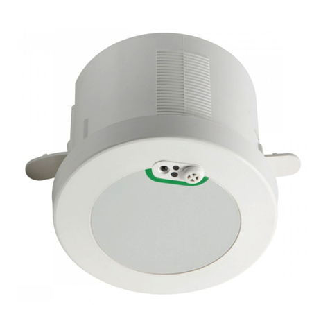
The COMRD is a sensitive, ultrasonic movement detector; it is essential therefore that it be installed on a rigid surface
that will not itself be subject to movement or vibration.
Fix directly to a rigid surface. Existing light switch can be retained. Use switch wire from switch as LIVE IN. A spare
connection has been provided for earth termination.
WHEN INSTALLING, REMEMBER
The detector is not for use outdoors.
Range is 10-15 metres for a walking target in a corridor and 5-8 metres for small hand-movements.
Best performance is achieved at a mounting height of 2-3 metres - in a corner - pointing into the room (max size 6.0m
x 6.0m) or one end of a corridor.
The detector is more sensitive to movementALONG the beam thanACROSS it.
The detector can see behind itself, so it should be positioned a metre or more inside the monitored area - particularly
in the case of racking aisles and corridors.
Ultrasonic detectors are sensitive to all moving objects including air movement. A mounting location should be
chosen thoughtfully, particularly where there are fans in the area, e.g. extract fans and computer cooling fans.
The detector should not be positioned within 25cm of a luminaire.
TECHNICAL/WIRING DETAILS
Switching capacity 10Amps . For use on 230V ac supplies only.
Terminal Capacity
1 x 2.5mm
or 2 x 1.5mm
N
N
L
E
E
COMRD L
OUT
LOAD
L
IN
Important Additional Notes
1. Ameans for disconnection must be incorporated in the fixed wiring in accordance with the current wiring regulations.
2. This equipment switches lights no more frequently than would a responsible human occupant. However, manufacturers of some
lighting types (e.g. ‘2D’ luminaires) may specify a maximum number of switching cycles in order to achieve a predicted lamp life.
Please check with the manufacturer of the luminaires to ensure that they are compatible with automatic controls in this respect.
SENSITIVITY CONTROLS
ON Sensitivity - Sets sensitivity to movement when lights are switched on
This is the normal sensitivity adjustment expected on any detector. Choose a setting as low as practical. (ON Sensitivity set to maximum will result in lights staying on permanently.)
OFF Sensitivity - Sets sensitivity to movement when lights have switched off
This additional sensitivity adjustment is useful in storage aisles, open plan areas etc. It enables a reduced sensitivity to be set for when an area is empty, so that fringe activity will not switch on the lights.
When fully clockwise, a very large movement is needed to switch on the lights whilst a much smaller movement (set by ON Sensitivity) will sustain them. In enclosed rooms or corridors, this control may be left in the fully anti-clockwise position
when the sensitivity will remain the same whether the lights are ON or OFF. The change takes 5 seconds after the lights have switched off to establish fully.
COMMISSIONING
Ensure that any heating / ventilation plant which may cause interference is switched ON. Set the PHOTOCELL control fully clockwise,
sensitivity controls fully anti-clockwise and the four switches to OFF then follow these simple commissioning instructions. We recommend
that the Off Sensitivity is not adjusted unless absolutely necessary and therefore the commissioning procedure is started from Step 2.
ON
OFF
4. OFF DELAY AND POWER-UP CONDITION
Sets the time delay following the last observed movement after which the
lights switch OFF.
With 3 and 4 in the OFF position, the delay time is 5 seconds which must only be
used for setting up purposes. In semi-automatic mode the lights are switched ON
by switching the wall-switch OFF then ON.
NOTE: In semi-automatic mode, Power-up ON must be selected, i.e. Switch 1
must be ON.
3. PHOTOCELL
Prevents lights being switched ON when there is adequate daylight.
Commission for movement before adjusting the photocell. Anti-clockwise
adjustment makes the photocell more active so that lights will be held OFF until it is
darker. A mid setting is generally suitable. The photocell may be overridden by
switching the normal light switch OFF then ON. The lights will come ON if Power-up
ON is selected, i.e. Switch 1 is ON.
2. ON SENSITIVITY
Sets the sensitivity to movement when the lights are ON.
Rotate the control clockwise so that the LED flashes in response to typical
movements expected at the extremities of the monitored area. Wait to ensure
that the lights switch off and that no interference signals are triggering the
detector.
DO NOT TURN TO MAXIMUM. Always adjust to the lowest setting consistent
with reliable performance.
1. OFF SENSITIVITY
Reduces the sensitivity to movement when the lights are switched OFF.
When set fully anti-clockwise, the sensitivity is the same with the lights switched
ON and OFF.
Wait outside the area for the lights to switch OFF. Re-enter the area and check
the point at which the lighting switches on again. Increase the setting until the
lights are switched on JUST AT THE POINT OF ENTRY.
LED
Coarse Sensitivity Adjustment
Normal setting is anti-clockwise. Turn clockwise to reduce
overall sensitivity (required only in special circumstances).
1 Power-up ON Power-up OFF
2 Semi-auto Auto
3 5 min delay Zero delay Add switches together
4 10 min delay Zero delay to select 15 minutes
ON OFF


