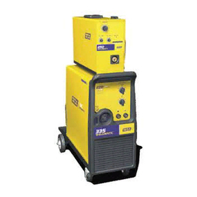
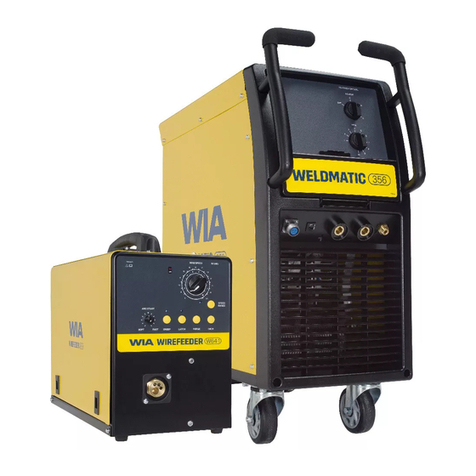
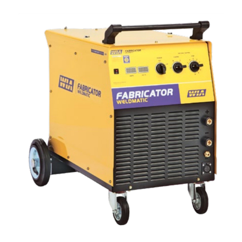
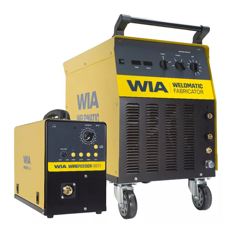
WIA WELDMATIC 600 User manual

WELDMATIC
600
MODELNO. CP6
CAT.
7524/6
6/80
FROM SERIAL NO.
6035
THEINFORMATIONCONTAINED IN THE FOLDER
IS
SET OUT TO ENABLE
YOU
TO PROPERLYMAINTAIN YOURNEW EQUIPMENT AND ENSURE THAT
YOU OBTAIN MAXIMUP4 OPERATINGEFFICIENCY.
PLEASE ENSURETHAT THIS FOLDER
IS
KEPT
IN
A SAFE PLACE FOR
READY REFERENCE WHEN REQUIREI?.
WHEN REQUESTINGSPAREPARTS, QUOTE THE MODEIi NO. AND SERIAL
NO. OF THEMACHINE AND THE PARTNO.OFTHEITEMREQUIRED.
FAILURETOSUPPLYTHISINFORMATIONWILLRESULT
IN
UNNECESSARY
DELAYS
IN
SUPPLYING THECORRECT PARTS.
WELDING INDUSTRIESOFAUSTRALIAPTY.LTD.
Melbourne
4294766
Newcastle
611668
Sydney
5342144
Adelaide
3523022
Brisbane
441391
Perth
3617088
Launceston
317004
Darwin
81
6427
&
843076

OPERATING
AND
MAINTENANCE
INSTRUCTIONS
-
WELDMATIC
600(CP6)
-
INTRODUCTION
GENERAL
Thismanualhasbeenpreparedespecially
for
use
in
familiar-
izingpersonnelwiththedesign,installation,operation,
maintenance,andtroubleshooting
of
this equipment.
All
inform-
ationpresentedhereinshould
be
givencarefulconsideration
to
assure optimumperformance
of
this
equipment.
RECEIVING/HANDLING.
Prior
toinstallingthisequipment,clean
all
packing
material
from. aroundtheunitandcarefullyinspectforany damage that
may haveoccurredduringshipment. Any
claims
for
loses
or
damage that m.ay haveoccurredintransit
must
be
filedbythe
purchaserwithWeldingIndustries
of
AustraliaPty.Ltd.
or
authorisedagentimmediately
(refer
to
EQUIPMENT
WARRANTY
card
enclosedwithOperatingInstructionManual).
When requesting irrbbrmation concerningthisequipment,
it
is
essential
to
supply
correct
Model identificationandmachine
serial
number.
SAFETY.
Before
theequipment
is
putintooperation,the
SAFETY
PRACTICES
section
at
the
back
of
this manual
MUST
BE
READ
COMPLETELY.
This
will
kelp
avoid
possibleinjurydue
to
misuseorimproper
weldingapplications.
"
CONTENTS
PAGE
NO.
GeneralDescription
l
SettingupforOperation
2-3
WeldingOperationInstructions
4
MaintenanceInstructions
5-6
Welding
Data
-
Table
"C"
7
-
Parts
List
CP6-02 Issue
4
8
-
AssemblyDrawing CP6-02
Issue
2
9
CircuitDiagrams
-
CP6-C9 10
Mobile
Kit
Assem.bly
-
Safety
Practices
Guarantee
Card

STANDARD
UNIT
The construction of thestandard package planthas been designed
forinstallation and operating
in
a
wide variety of applications,
such
ashighproductionfactories and generalfabrication shops.
"WELDMATIC"
Plantsconsist of threebasic
units:-
l,
ConstantPotentialRectifier Power Source.
2.
Semi-Automatic Wire Feeder.
3,
Welding
Gun
and Cable Assembly.
Separateoperating and maintenance instructionsare provided
forthewirefeeder andgun cables.
1.
-
POWER
SOURCE
-
FEATURES
The standard
C.P.
rectifier power source
is
housed
in
a
drip-
proof enclosure.
Lifting
lugs
areprovidedforcranetrans-
portation. For
units
with
wheelmounting foursolidrubber
tyredwheelsareprovided:the two front wheels aresteerable
permittingeasy movement
in
restrictedfloorspace.
A
push
bar
is
provided
on
the
front
of the machine and
a
gascylinder
carrier
with
a supportbracket and chain
at
therear.
A
110
voltplugsocket is located
on
therear panel
for
connection
of gaspreheater when welding
with
C02
gasshield. Located
on
thefrontpanelare
a
coarsevoltageselectionswitch,fine
voltageselectionswitch, power
ON/OFF
switch,controlfuses,
wirefeeder
plug
socket and rectifier power outletsockets.
2.
CONSTRUCTION
Thepower source
is
a ConstantPotentialSilicon Diode Rectif-
ier
B.C.
Welder,
with
a threephasetransformer and
a
three
phase rectifierbridge. Connected
in
the
outputcircuit
is
an
inductance
unit
providingthe"inductance"ordegree of slope
necessaryforvariousweldingcurrents.Cooling
of
thesili-
con diodes,transformerwindings and inductance
unit
isby a
singlephaseaxialfan. Thepower source
is
protectedagainst
fanfailure and overheating
by
thermostats mountedon diode
heatsinks.
3.
WELDING
PROCESS
Gas metalarcwelding
within
thecapacity
of
the power source
can be carried
out
with
tke
followingequipment:-
a) Semi-automatic wirefeeder model
W14.
b)
Semi-automatic wirefeeder
with
spottimer
W14-20.
c) "Hobart"spool gun welding
unit
model
SP9
with
CV2
d)
"Mini-mig" push and
pull
gun
and control.
controller.
4.
WELDING
CAPACITY
Power SourceCapacity
is
asfollows:-
600
Amps,42 volts,
100%
duty
cycle.

-1
-2-
5.
SUPPLY
AND
WELDING
CABLES.
Power
Sources
are
suitableforconnection
to
a
415 volt 50
Hertz
3
phasesupply.
Therecommended fuse
size,
primary
cable
sizeandwelding
cable
size
are
as
follows:-
a)
Fuse
-
50
amp.
b)
Primary
Cable
-
4 core 77/0.40
T.R.S.
c)
Welding
Cable
-
998/0.30
T.R.S.
6.
SHIELDING
GASES.
a) Welding
Grade
C02
for
a11
mild
andalloy
steel
weldingin
"
thicknessesranging
from
lmm
upwards.
b)
Argon/C02
or
Argon/Oxygen mixtures
for
all
applicationson
low
currentsrequiring minimum
of
spatteronsheet
steel
and
for
stainless
steel
welding.
c)
Argon/Oxygenand
Argon/C02
mixtures
for
prime
quality
weld-
ing
of
stainless
steel.
d)
Argon (pure)
for
all
aluminium.welding.
7.
§ETTING
UP
UNIT
FOR
OPERATION.
a)
-
General
Assembly
of
Packaqed
Plant
(Refer
Drawing
AM1.16)
The
Rectifier
Welder
is
shipped
with
the
skids
or
wheels
unbol-
ted.
Bolt
on
the
wheel
assemblies
with
the
steerable
(swivel)
wheelsnearestthefrontpanelandpush
bar.
If
a
"Mini-Boom"
wire
feedermounting
is
supplied,
locate
thevertical
boom
post
in
the
special
swivel mount
at
the
rear
of
themachine.
Locate
the
Wire
Feederontheswivelmount,ensuringthatthe
fibre
thrustwasher
is
on the
pivot
pin.
Check
that
the
"Wire
Feeder"
is
free
toswivelin
all
directions.
If
necessary
apply
a
small
am.ount
of
graphite
grease
to
shaft.
b)
Connection
to
MainsSupply.
Note:
This
work
shouldonly
be
doneby
a
qualifiedelectrician.
Thepowersource
is
designed
for
connection
to
415 volt,
50
hertz,
3
phase
supply
and
the
supplyvoltageshould
be
ascert-
ained
before
connectingthemachine.
Access
to
supplyconnec-
tion
terminals
in
machine may
be
gainedbydoorinrighthand
side
panel.
Use
a
flexible 4
core
primary
cable
for
portable
machinesand
clamp
cable
to
ensurethat
there
is
nostrainon
cable
connections.The
earth
(or
ground)connection(green/
yellow)must
be
securelyfastenedto
the
'earth'
terminal
on
themachineadjacent
to
thesupplyconnectionterminals.
CAUTION
Before
insertingprimary
cable
pluginmainssupply
socket:
ensurethat
switch
on
both
plug
socket
andwelding
machine
is
in
'OFF'
position.

-
3-
c)
"
CONNECTION
OF
CABLES/HOSES,
ETC.
Withunitswitched
'OFF'
connectcontrol
cable
(6
pinplug)
from
power
sourceto
wire
feeder.
Connect
gas
hosefrom
wire
feeder
to
gas
regulator/flowmeter,ensuring
all
connections
are
tightenedfirmly.
If
C02
Gas
Shield
is
beingused,plug
heater
into
110
volt
socket
at
rear of
unit.
Next
insert gun
cable
into
socket
of
wire
feeder
outputguideandretaininplace
with
set
screw
provided.
Set
screw
shouldnot
be
tightened
so
as
to
preventgun
cable
fromswivelling.Connect
"Gas
Hose"
and "Gun Switch"
leads
to
respectivesockets.
d)
WELDING
CABLES.
All
G.M.A.
welding
is
done
with
electrode
wire
connectedto
"positive"
pole
comrn.only known
as
D.C.
reversepolarity
(D.C.R.P.)
therefore,connecttheshortjumper
lead
from
'I+''
socketon
machine
toterminallugongun
cable.
Thework lead
("negative")should
be
pluggedinto
the
'I-''
socketon
the
machine.Theplugsofthewelding
cables
must
be
fullyinserted
inthe
sockets,
to
preventaccidentaldisconnection.
To
avoid
error,
weldingshouldnot
be
attempted
untilallconnections
have
been
secured.The
wire
feeder may
be
installed
remote
from
the
power
source,in
which
case,
extension
lead
sets
comprising
power
cable,
gas
hose
andcontrol
cable
(four
core)
arerequired
inaccordance
with
the
desired
length.Standardlength
avail-
able
from
stock
is
9
m.etres.
3)
WIRE
FEEDER
AND
GUN
CABLE.
Fit
a
spool
of
wire
to
the
wire
feeder
(see
notesin
"Wire
FeederInstructionManual").Tightenthe
"brake"
screw
until
a
slightbraking
effect
is
felt when turningthe
wire
spool
by
hand
to
prevent"over-run" when
wire
feed
stops.
The
wire
drive
rolls
and
inlet
wire
guideshould
be
selected
inaccordance
with
the
diameter
andtype
of
wire
beingused.
Refer
to
current
wire
feedermanual
for
correct
selection
of
wire
feed
rolls
andinput
guides.
0.8mm.
=
0.030"
1.6m
=
1/16"
0.9mm
=
0.035"
2.4m
=
3/32"
1.2mm
=
0.045"
3.2m
=
1/8"
The
gun
cable
andgun
are
normally delivered with thecontact
tip
and
liner spring
for
wire
size nominated,but
check
that
both
are
correct
sizefor
wire
beingused.

8.
-4-
WELDING
OPERATION
INSTRUCTIONS
SINGLE
FUNCTION
CHECK
Unit
is
now
ready
for
operation,but
prior
t
o
commen
ina,
thefollowins"functionscheck''
is
recommended,cing
weld-
switchon
poGersourceandcheck
air
flow.
See
that
all
weldinglead
plugs
are
inserted
in
the
correct
polarity
sockets
-
electrode
"positive"
,
work
"negative". Check
all
weldingconnections
andplugsfortightnessparticularly"work"
clamp.
Next
ensurethat
all
control
cables
and
gas
hoses
are
securely
connectedandthat
Gas
Heater
(for
C02
only)
is
pluggedinto
socket
at
rear
of
power
source.Switchon
wire
feeder,
indic-
ator
lightshould now
show
"Power On".Open
Gas
cylinderfully
andcheckcontentsgauge
for
adequategassupply.
Press
"Gas
Purge"switchand
set
gasflowinaccordancewith
weldingrequirements,
at
the
same
time
checkthat
gas
flow
is
adequate
from
gunnozzle,
Set
"wire
speed"control
to
desired
wire
speed.
Press
"wire
inch"switchandcheck
wire
feed
for
correct
pressureondrive
rolls.
Pressureshould
be
sufficient
to
preventany''slip" when feedingthroughgunandcable.
Next,
close
gunswitchmomentarily
for
wire
feed,
gas
flow
and
welding
power
check.
Set
thevoltage
selector
switchesin
accordance
with
required
voltage
(see
welding
table),
unit
is
now ready
for
welding.
The
weldingcurrent
is
determinedautomaticallyby
"Wire
Speed".
Theelectrode
wire
is
fed
at
thepre-selected
speed
bythe
driverollsthroughthegun
cable
to
the
arc
at
a
constant
speed,
unchanged
except
when
reset
bythe
"Wire
Speed"
control. The
higherthe
wire
speed,
thehighertheweldingcurrent,
as
will
be
indicatedby
the
ammeter.
The
outputvoltage
of
the power
source,indicatedbythevoltmeter when
the
gunswitch
is
closed,
is
dividedinto
a
number
of
steps
by
Coarse
Selector
andFine
Selector
switches.
The CP6
has
Coarse
Voltage
and
FineVoltageSwitches,eachwith
six
steps,
giving
36
voltage
settingsforthemachine.The
inductanceterminal
sockets
are
numbered
''1
-
4".
No.1
socket
should
not
be
usedforweldingcurrents
over
300
amps.
Depend-
ingonthetype
of
weldingconditions,variousinductancevalues
are
required.Thetypical
weld
settingchartindicatesthe
recommended socketsforvariousweldingconditions.
As
a
general
rule,lowweldingcurrentsrequireinductance
No.
1
or
2.
For
aluminiumandtubularfluxcored
wires,
inductancesocket
No.
2
is
usedexclusively.

-5-
The followingsequence
of
weld setting
is
recommended:-
a) Consulttypical weld settingchart.
b)
Selectweldingcurrent most suited
to
theapplication
by
followingthesettings of wire speed and voltage shownon the
settingchart.
To
"tune"each weld setting,adjustwire
speed only.
c)Ifvoltage
is
too low fortheapplication,wire"stubbing"
will
occur,particularlyatstart of weld and weld contour
will
be very convex.
If
thevoltage
is
toohigh,metal
transfer
will
be erratic
with
excessspatter.
d)
With
weldingcurrent and voltage matched theresult
will
beanoptimum tunedweldingcondition
with
a smooth spatter-
freearc.
10.
SAFETY
DEVICES
In
theevent
of
the power source becoming overheatedthether-
mostats on thediodeheatsinks
will
operatepreventingfurther
welding. The thermostats
will
automaticallyreset and
with
thecoolingfanoperating
this
will
takeapproximately
10
min-
utes.
A
check should be made toascertainthereasonforthe
over-heating such
as
fannotoperatingorairflowrestricted.
Fusesprovidedfor allcircuitsareasfollows and are
indicated on thefrontpanel:-
Fuse
El
-
3
amps (Delayed action)
Fuse
E2
-
3
amps
(
'l
'I
1
Fuse
E3
-
5
amps
(
'I
'I
1
Fuse
E4
-
5
amps
(
'I
'I
1
11
.
ENT
ENANCE
a)
Power Source
Apart from thefantherectifier has no rotary components.
To achievecompletedissipation of heat from theactive com-
ponents,therectifier should be thoroughly blown off
with
dry
compressed airafter
6
months' operation.Cleaningshould
be carriedoutatshorterintervalsif
dust
accumulation
is
considerable.
Prior
to
cleaning, remove the
unit
cover
by
detachment
of
lugs
and
thefixing screws. Thus
a11
the components of the power
source
will
bs
accessible.
b)
The wirefeedmotor/gearbox
is
pre-packed
with
grease and
needs no otherlubrication. Change thegreaseafter approx-
im.ately
14,000
servicehours.(see Wire Feeder Instruction
Manual
.
The driverollers
and
theinner
wire
guides
should
be kept
clean.
If
necessary,
blow
off
theinside
of
the
wirefeeder
with
compressed air.

-6-
c)
Gun and
Cag
Remove any
spatter
which
might
adhere
to
the
nozzle
bore
so
that
the
shieldinggasoutflow
is
not
impeded.
The
condition
of
the
contacttubesshould
be
regularlychecked.
Damaged
and/orburnt
tubes
are
animpediment
to
trouble-freewelding
operationandshould
be
replacedimmediately.
Trouble-freeoperation
depends
to
a
largeextenton
the
good
conditionandcleanliness
of
theinner
wire
liner
(See
Instr-
uctionson Gun
Cables).
12.
WELDING
OPERATION
Neverobserve
the
arc
with
unprotectedeyes.
It
is
ofimpor-
tancethatthe
welder
wear
protectiveclothingproviding
sufficientsafety.
13.
STOPPAGES
AND
THEIR
ELIMINATION
Themachineshould
be
checkedonlyby
a
fully
skilled
electr-
ician.
If
the
unitstopsworking,
first
determinewhetherstoppages
are
initiatedby
the
mains
(for
instance,burntfuse)
or
by
the
supply
cable
(looseconnection,
cable
break)
orby
the
unitproper.
If
thethreeterminals
L1,
L2
and
L3
on
the
primaryterminal
board
are
correctlyconnectedto
the mains (voltmeter reading)
thecauseofthestoppagemust
be
soughtintheunit
itself.
The wiringdiagramonthenextpages
will
facilitatethe
location
of
the
defect.

-7-
WELDING
DATA
-
TYPICAL
VALUES
Shielding Gas
is
welding
Grade
C02
used
with
a
Gas
Preheater.
ContactTip1.5minside
of
Gas Nozzle.
Wire
"Stick
Out"
6
-
9m.m
up
to
200
amps.
12
-
19mm
over
200
amps.TheseTables
are a guideonlyforinitialmachinesettingandfiner
adjustments may benecessary
to
achieve optimumwelding
characteristicsfor
the
application. Recommended machine
setting method
is
to
set
Voltage
Switches,
Inductanceand Gas
Flow asperTablethenadjust
wire
speed toobtain recommended
current.
:ect-
fier
JP6
Wire
Size Gas
0.9m
(Solid
Wire)
1.2m.
(Solid
Wire)
10
Lit./Min
(for
vertical Down)
15
Lit./Min
1.6mm
15/17
(Fluxo-
Lit./Min.
fil)
2.0m.
(Fluxofil)
2
.
4mrn
(Fluxofil)
Wire
Speed
Metres
Per
Min.
3.9
6.3
2.2
3.2
4.4
5.7
5.8
7.6
9.0
10.0
5.1
6.4
5.5
6.6
Coarse
-
2
2
2
3
3
3
3
4
5
5
5
5
5
6
4
1
190
4
2 200
2
3
250
2
2
330
3
2
360
4
2
380
5
2
450
6
2
500
1
2
550
Volt
18
21
20
21
22
23.5
26
27
31
32
33
34
34
35
NOTE:
Wire
speed
is
shown
in
metres/minuteandarenotdial
calibrationsettings.

-
I
TEP
NO.
-
2
2.1
2.2
2.3
3
3.1
4
4.1
4.2
5
S
9
18
21
22
24
25
26
26.1
27
28
29
30
32
33
34
37
38
39
40
37.1
37.2
8
DRAWING
NO.
CP6-02
-
SPAREPARTS LISTISSUE
5.
PART
NO.
CP6-5
CP6-5/2
CP6-5/3
CP3-9/8
CP6-8
,
CP6-19
CP6-2
CP6-7/1
CP6-7/2
CP25-0/7
CP3-0/4
14235-0/6
CP15-0/7
CP5-25
CP5-0/19
AM1
6
CP15-0/14
TC262
TC262N
CP3-0/47
CP6-0/35
w1-22
CP6-0/47
CP5-0/13
CP5-0/14
CP5-0/15
W1-23
CP22-3/13
CP6-20
CP6-21
K10
K11
DESCRIPTION
RECTIFIER ASSEMBLY
DIODE
DIODE (R)
THE
R?.!lOS
TAT
TRANSFORMER ASSEMBLY
PRIMARY/SECONDARY COIL
INDUCTANCEASSEMBLY
LEFT
HAND
INDUCTANCE COIL
RIGHT
HAND
INDUCTANCE COIL
CONTROL TRANSFORMER
FAN
BLADE
FAN
MOTOR
GAS
HEATERPLUGSOCKET
RECTIFIERPROTECTION ASSEMBLY
WELDING CONTACTOR
OUTPUT TERMINALS
CONTROL PLUG
GAS
NIPPLE
GAS
NIPPLE NUT
VOLTMETER 0-60V.
AMPETER 0-800A.
INDICATORLIGHT
APNTER SHUNT 0-800A
POWER
ONYOFF
SWITCH
COARSE VOLTAGE SWITCH
FINE VOLTAGE SWITCH
FUSE HOLDER
STAND
OFF
INSULATOR
RESISTOR
SERIESRESISTOR
3AG.
3A
DELAY FUSE
3AG.
5A
DELAY FUSE

6
0 0
0
0
C
b

SAFE
PRACTICES
IN
UStNG
WELDING
EQUIPMENT
These notes are provided in the interests
of
improving operator safety.They should be considered
only as a basic guide
to
Safe Working Habits.
A
full list
of
Standards pertaining
to
industry is available
from the Standards Association of Australia, also various State Electricity Authorities, Departments of
Labour and Industry or Mines Department and other Local Health or Safety Inspection Authorities may
haveadditional requirements.
EYE PROTECTION
NEVER
LOOK
AT
AN ARC WITHOUT PROTECTION. Wear a helmet with safety goggles or glasses
withsideshields underneath, withappropriate filter lenses protected by clear cover glass. This is a
MUST forwelding,cutting,andchipping to protectthe eyes fromradiant energy andflyingmetal.
Replace the cover glasswhen broken, pitted,or spattered.
WELDING
CURRENT
SHADE
NUMBER
Below
30
Amps
.......................................
6
30
-
75
Amps
.........................................
8
75
-
200
Amps
.......................................
10
200
-
400
Amps
......................................
12
Above
400
Amps
.....................................
14
BURN PROTECTION.
The welding arc is intense and visibly bright.
Its
radiation candamage eyes, penetrate lightweight
clothing,reflectfromlight-coloured surfaces, andburntheskinand eyes. Burns resultingfrom gas-
shielded arcs resemble acute sunburn, butcan be moresevereand painful.
Wear protective clothing
-
leather or heat resistant gloves, hat, and safety-toe boots. Button shirt
collar and pocketflaps, andwear cuffless trousers
to
avoid entryof sparks and stag.
Avoid oily or greasy clothing.A spark may ignitethem.Hotmetal such as electrode stubs and
workpieces shouldnever behandled withoutgloves.
Ear plugs should beworn when welding
in
overhead positions or in a confined space. A hard hat
should be wornwhen others are workingoverhead.
Flammable hair preparations should not
be
used bypersons intendingtoweld or cut.
TOXIC
FUME
PREVENTION.
Adequateventilationwith air is essential. Severe discomfort, illness ordeath can resultfrom
fumes, vapors, heat,
of
oxygen depletion that welding or cutting may produce. NEVER ventilate with
oxygen.
Lead, cadmium, zinc, mercury,andberylliumbearingandsimilarmaterials when welded or cut
may produce harmful concentrationsof toxic fumes. Adequate local exhaust ventilation must be used,
or
each person in the area as well as the operator must wear an air-supplied respirator.
For
beryllium,
bothmust be used.
Metals coated withor containing materialsthat emit fumes should not be heated unless coating is
removedfromtheworksurface,the area
is
wellventilated, or the operator wears an air-supplied
respirator.
Work inaconfined space only while
it
is
beingventilatedand,
if
necessary, whilewearing air-
supplied respirator.

Vapours from chlorinated solvents can be decomposed by the heat of
the
arc (or flame)
to
form
PHOSGENE,
a highly toxicgas, andlungand eyeirritating products.The ultra-violet (radiant) energy
of
the arc can also decompose trichlorethylene and perchlorethylene vapors
to
form phosgene.
Do
not
weld or cut where solvent vapors can be drawn into the welding or cutting atmosphere or where the
radiant energy can penetrate
to
atmospherescontaining even minuteamounts
of
trichlorethylene or
percholorethylene.
FIRE
AND
EXPLOSION
PREVENTION.
Beaware thatflying sparks or falling slagcan pass through cracks, along pipes, through windows
or doors, and through wall
or
floor openings,out ofsight of the operator. Sparks andslag can travel up
to
10
metresfromthe arc.
Keepequipmentcleanandoperable,freeof oil, grease,and (inelectricalparts)ofmetallic
particles that can cause short circuits.
If
combustibles are present in the workarea,
do
NOT
weld or cut. Move the work
if
practicable,
to
anarea free of combustibles, Avoid paint spray rooms,
dip
tanks, storage areas, ventilators. If the work
cannotbemoved,movecombustibles at least
10
metresaway out of reachofsparksandheat; or
protect against ignition with suitableand snug-fltting fire-resistant covers or shields.
Walls touching combustibles on opposite sides should not be welded on
or
cut. Walls, ceilings,
and floornear work should be protected by heat-resistant covers or shields.
A
person acting as Fire Watcher must be standing by with suitable fire extinguishing equipment
duringand for sometime after weldingor cutting
if;
R
Combustibles (includingbuildingconstruction)arewithin
10
metres.
m
Combustibles are further than
10
metresbutcan be ignited bysparks.
R
Openings(concealedor visible) Infloors or walls within
10
metres may exposecombustibles
m
Combustibles adjacent
to
walls, ceilings, roofs, or metal partitions can be ignited by radiant
or
After workis done, check that areaisfree
of
sparks, glowing embers, and flames.
to
sparks.
conducted heat.
An tank or drum which has contained combustibles can produce flammable vapors when heated.
Such acontainermust never beweldedon orcut,unless
It
has first beencleanedasdescribed in
AS.
1674-1974,
the
S.A.A.
Cutting and Welding Safety Code.This includes a thorough steam or caustic
cleaning(orasolventorwaterwashing,depending on thecombustible’ssolubility),followedby
purgingand inerting with nitrogenor carbon dioxide,and using protective equipmentas recommended
in
AS.1674-1974.
Water-fillingjust below workinglevel may substitute for inerting.
Hollow castings or containers must
be
vented beforewelding or cutting. They can explode. Never
weld or cut where the air may contain flammable dust, gas,or liquid vapours.
SHOCK
PREVENTION.
Exposed conductors or otherbaremetal intheweldingcircuit, or ungroundedelectrically alive
equipment can fatally shock a person whose body becomes a conductor. Ensurethat the machine is
correctly connected and earthed.
If
unsurehave machine installed by a qualified electrician.On mobile
orportableequipment,regularlyinspectcondition
of
trailingpower leads and connectingplugs.
Repairor replace damaged leads.
Fullyinsulatedelectrodeholdersshouldbe used.
Do
not use holderswithprotruding screws.
Fully insulated lock-type connectors should be used
to
join welding cable lengths.
Terminalsandotherexposedparts of electricalunitsshould have insulatedknobs or covers
secured before operation.

t
.
h)
I,
c.
GI
I
I
dk
bl
I
l
This manual suits for next models
1
Table of contents
Other WIA Welding System manuals

WIA
WIA CP27-9 User manual

WIA
WIA weldmatic 350i CP139-2 User manual

WIA
WIA Weldmatic 180s CP17 User manual

WIA
WIA Weldmatic Weldarc 145i User manual

WIA
WIA CP117-2 User manual

WIA
WIA WELDARC 200DC User manual

WIA
WIA MC105-0 User manual

WIA
WIA TIGARC 140DC MC86-0 User manual

WIA
WIA Weldmatic 200i MIG User manual
WIA
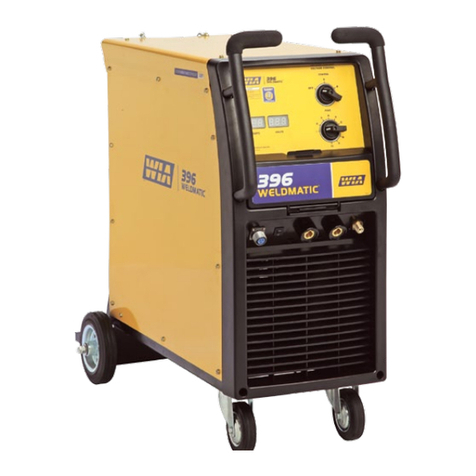
WIA Weldmatic 396 User manual
WIA
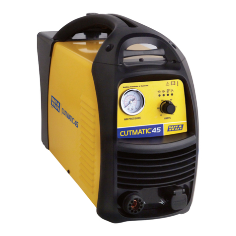
WIA Weldmatic 396 User manual

WIA
WIA Weldmatic 256 User manual

WIA
WIA WELDMATIC 350 User manual

WIA
WIA UTILITY UTAC13-0 User manual

WIA
WIA Cutmatic 45 Series User manual
WIA
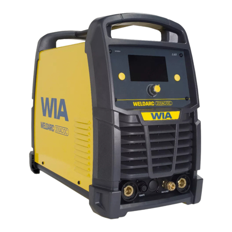
WIA WELDARC 135 User manual

WIA
WIA WELDARC 200AC/DC User manual
WIA
WIA WELDMATIC 180 User manual

WIA
WIA Weldmatic 205S User manual

WIA
WIA WELDMATIC 335 User manual