INSTALLATION · MANUAL
3. Installation/Montage
Zur Installation sind die nationalen Sicherheitsvorschriften zu
beachten. Es wird keine Haftung für unsachgemäßen Einsatz oder
Montage übernommen. Bei nachträglichen Änderungen an den
Leuchten wird keine Haftung übernommen. POW-LED Leuchten
müssen immer in Reihenschaltung an entsprechenden Konstant-
stromnetzteilen (siehe Betriebsgeräte)betrieben werden (350 mA).
Die Leuchtengehäuse sind nicht zu demontieren, da zum Schutz
Kabel und die POW LED Platine vergossen ist.
Montage der Scheinwerfers in Beton, Pflaster, Platten, Holz-
dielen, Erdreich, Kies, Rasenflächen oder Beete möglich. Da bei Pro-
jekten die Bodenverhältnisse und Einbausituation variieren ist keine
allgemein gültige Montageanleitung möglich. Die Piktogramme
verdeutlichen typische Montagebeispiele.
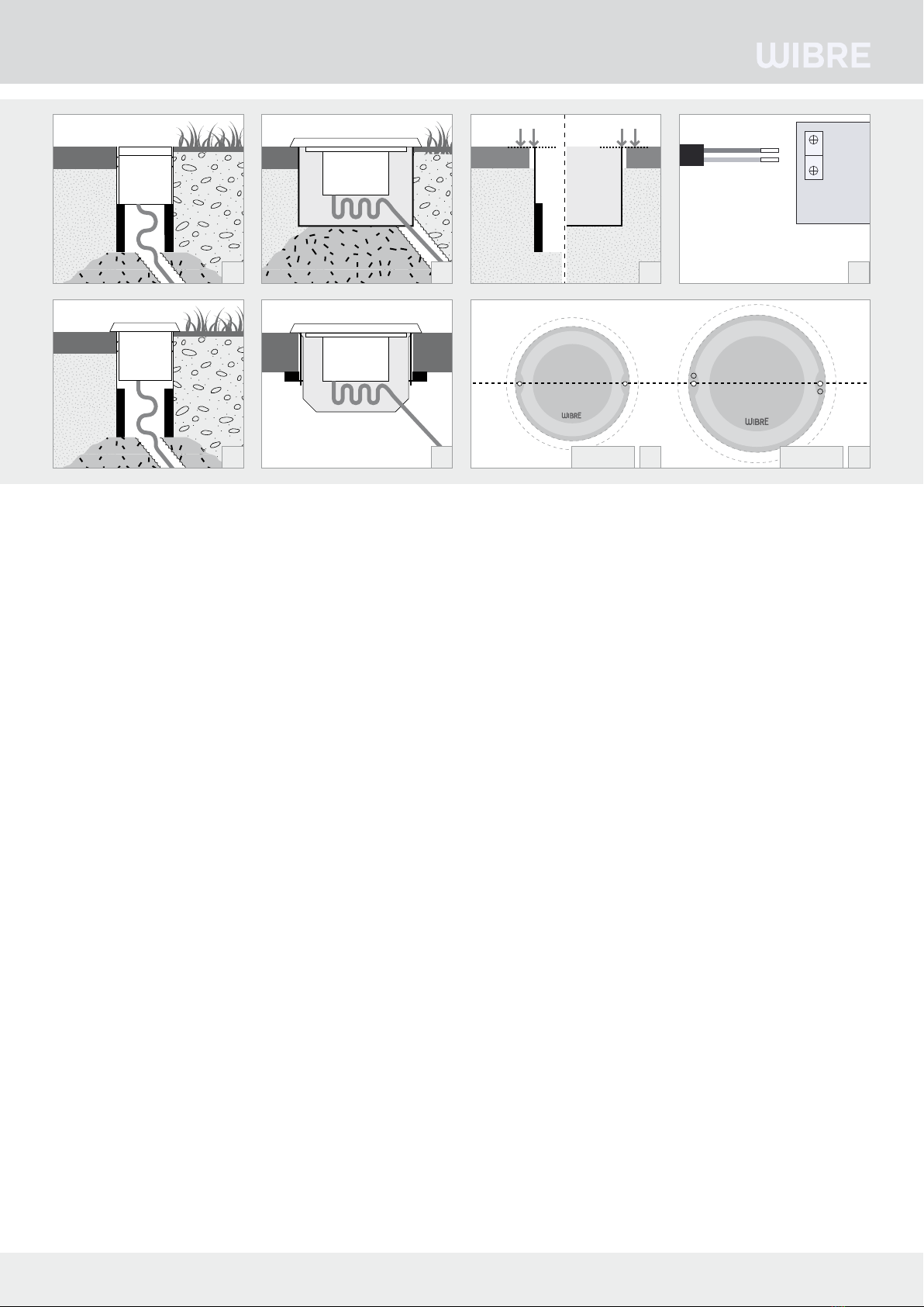
3.1./3.2. Einbau Serie 4.0010/4.0011 mittels Aluminium-
einbauhülse in Beton, Asphalt, Erde o.ä.
3.3. Einbau Serie 4.0020/4.0021/4.0025/4.0026
mittels Kunststoffeinbaugehäuse in Beton, Asphalt, Erde o.ä.
3.4. Einbau Serie 4.0020/4.0021/4.0025/4.0026
mittels Kunststoffhohlwandgehäuse in dünnwandige Systeme o.ä.
Montage Serie 4.0010/4.0011
Bei Einbau mit Aluminiumeinbauhülse sollte für eine sichere
Standfestigkeit der Einbauhülse gegebenenfalls ein Fundament
vorgesehen werden und für ausreichende Drainage z.B. durch Kie-
sauffüllung/Sand gesorgt werden. Eintretendes Oberflächenwasser
muss aus der Einbauhülse abfließen können. 3.1./3.2.
Für die Dichtigkeit und spätere Montage des Scheinwerfers muss die
Oberkante Einbauhülse mit der Oberkante Abschlussfläche
(z.B. Bodenbelag, Pflaster oder Holz) bündig sein 3.5.
Achtung: Nur werkseitig angeschlossenes Kabel verwenden.
Gewünschte Kabellänge bei Bestellung angeben, da ein späterer
Anschluss direkt an der Leuchte nicht möglich ist. Bei mechanischer
Beanspruchung sollte das Kabel zusätzlich in einem Schutzrohr
verlegt werden. Der Anschluss des Silikonkabels an das Hauptnetz
sollte imTrockenen erfolgen bzw. bei Anschluss direkt im Erdreich
sind spezielle Anschlusseinheiten mitVergussmasse zu verwenden.
(z.B.WIBRE Art.Nr. 9.9010.68.16)
Einzelanschlussader entsprechend den Vorschriften an den Netztei-
len elektrisch anschließen. 3.6. Die maximale Anzahl von Leuchten
und Anschlußart siehe auch Manual des entsprechenden Netzteiles.
Die Leuchte in die Einbauhülse einschieben und bis auf Oberkante
Abschlussfläche eindrücken
Montage Serie 4.0020/4.0021/4.0025/4.0026
Bei Einbau mit Kunststoeinbaugehäuse in
Beton, Asphalt oder Erde sollte für eine sichere Standfestigkeit der
Einbauhülse gegebenenfalls ein Fundament vorgesehen werden und
3. Installation/Mounting
When installing, observe the national safety regulations. We are not liable
for any improper use or installation. No liability will be accepted in case of
subsequent modification to the lights.
POW-LED lights must always be operated in series with appropriate
constant-current power sources (see operating devices) (350 mA).
The light housings must not be removed, since the cable and POW LED
printed circuit board are covered with waterproofing for protection.
Installation of the spotlights is possible in concrete, pavement,
slabs, wooden floor boards, soil, gravel, lawn or garden beds. Since ground
conditions and installation circumstances vary, no general installation
instructions can be provided. The icons symbolise typical installation
examples.
3.1./3.2. installation of series 4.0010/4.0011 using aluminium
installation sleeves in concrete, asphalt, soil, or the like.
3.3. Installation of series 4.0020/4.0021/4.0025/4.0026
using plastic installation housing in concrete, asphalt, soil, or the like.
3.4. Installation of series 4.0020/4.0021/4.0025/4.0026
using plastic hollow-wall housing in thin-walled systems or the like.
Installation of series 4.0010/4.0011
When installing with aluminium installation sleeve, a foundation as well
as sufficient drainage, e.g. with gravel/sand filling, might be needed for
secure stability of the installation sleeve. Entering surface water must be
able to flow out of the installation sleeve. 3.1./3.2.
For tightness and later installation of the spotlight, the upper edge of the
installation housing must be flush with the upper edge of the top layer
surface (e.g. with the decking, pavement or asphalt) 3.5.
Attention: Use only cable connected at the factory. Specify desired
cable length when ordering, since a later connection directly to the light
is no longer possible. In case of mechanical load, the cable should also be
laid in a protective tube.
The silicone cable should be connected to the mains supply under dry
conditions, or special connection units with sealing compound are to be
used if connected in the soil. (e.g. WIBRE article no. 9.9010.68.16)
Electrically connect individual wires to the power supply according to regu-
lations. 3.6. For the maximum number of lights and type of connection,
also see the manual of the corresponding power supply.
Push the light into the installation sleeve and press down until it is flush
with the top layer surface.
Installation of series
4.0020/4.0021/4.0025/4.0026
For installation with plastic installation
housing in concrete, asphalt or soil, a foundation as well as sufficient
drainage, e.g. with gravel/sand filling, might be needed for secure stability
of the installation sleeve. Entering surface water must be able to flow out
of the installation sleeve. 3.3.
3. Installation/Montage
Respecter les prescriptions nationales applicables en matière de sécurité.
Nous déclinons toute responsabilité pour l’utilisation ou le montage non con-
forme. De même, nous réfutons toute responsabilité pour les modifications
réalisées sur les luminaires. Pour leur exploitation, les projecteurs à POW-LED
doivent toujours être reliés en série au bloc d‘alimentation en courant continu
correspondant (voir blocs d‘alimentation) (350 mA).
Ne pas démonter les boîtiers de projecteur, étant donné que le câble et la
platine POW LED sont scellés.
Montage du projecteur dans le béton, les pavés, les plaques, les lames
de bois, la terre, le gravier, les espaces verts ou les plates-bandes. Étant
donné que dans les différents projets, les conditions du sol ainsi que la situ-
ation d’intégration varient, nous ne pouvons établir une notice de montage
générale. Les pictogrammes expliquent les exemples de montage type.
3.1./3.2. Montage des séries 4.0010/4.0011 avec tube de
montage en aluminium dans le béton, l‘asphalte, la terre, entre autres.
3.3. Montage des séries 4.0020/4.0021/4.0025/4.0026
avec boîtier de montage en plastique dans le béton, l‘asphalte, la terre, entre autres.
3.4. Montage des séries 4.0020/4.0021/4.0025/4.0026
avec boîtier de montage en plastique dans les constructions à parois fines.
Montage des séries 4.0010/4.0011
Lors du montage avec tube en aluminium, il est recommandé de prévoir le
cas échéant une fondation en béton afin de garantir une bonne stabilité
du tube de montage et d‘assurer un drainage suffisant, par ex. par un
remplissage de gravier/sable. L‘eau de surface pénétrant dans le tube de
montage doit pouvoir s‘écouler. 3.1./3.2. Pour l’étanchéité et le montage
a posteriori du projecteur, le bord supérieur du tube de montage doit affleurer avec
la surface de finition (p. ex. le revêtement de sol, les pavés et l’asphalte). 3.5.
Attention: utiliser uniquement les câbles raccordés en usine. Indiquer
la longueur souhaitée du câble lors de la commande, étant donné qu‘un rac-
cordement ultérieur directement au projecteur ne sera pas possible. En cas de
sollicitation mécanique, le câble doit être posé dans une gaine de protection.
Le raccordement du câble en silicone au secteur doit être réalisé en milieu sec
et, dans le cas d‘un raccordement direct dans le sol, il convient d’utiliser des
unités de raccordement spéciales à masse de scellement. (par ex. WIBRE Réf.
9.9010.68.16) Raccorder les différents conducteurs aux blocs d‘alimentation
conformément aux prescriptions. 3.6. Pour le nombre maximal de
projecteurs et le type de raccordement, voir également le manuel du bloc
d‘alimentation correspondant. Insérer le projecteur dans le tube de montage
et l‘enfoncer jusqu‘à affleurer le bord supérieur de la surface de finition.
Montage des séries 4.0020/4.0021/4.0025/4.0026
Lors du montage avec boîtier en plastique dans
le béton, il est recommandé de prévoir le cas échéant une fondation afin de
garantir une bonne stabilité du tube de montage et d‘assurer un drainage
suffisant, par ex. par un remplissage de gravier/sable. L‘eau de surface
pénétrant dans le tube de montage doit pouvoir s‘écouler. 3.3.
2/4 WIBRE Elektrogeräte Edmund Breuninger GmbH & Co. KG · Liebigstrasse 9 · 74211 Leingarten/Germany
T
elefon:
+49
(0)
7131
9053-0
·
T
elefax:
+49
(0)
7131
9053-19
·
E-Mail:
[email protected]rot/red
schwarz/
black
+
–
+
–
sec
Netzteil
Ballast
Alimentation
3.1
3.2
3.3 3.5
3.83.74.0020/21 4.0025/26
3.6
3.4
Hinweis: Reihenverschaltung bauseits
Reference: Serial connection made on site
Référence: connexion en série a fairre sur place