manuals.online logo
Brands
  1. Home
  2. •
  3. Brands
  4. •
  5. Wibre
  6. •
  7. Outdoor Light
  8. •
  9. Wibre 4.0071 User manual

Wibre 4.0071 User manual

INSTALLATION · MANUAL
4.0071
Bodeneinbau-Scheinwerfer mit Einbaugehäuse
Ground mounted-Light with built-in pot
Projecteur de Sol avec boîtier d‘encastrement
1. Anwendung
Bodeneinbauscheinwerfer geeignet für Markierung, Akzentuierung
und Beleuchtung von Gebäuden, Fassaden, Skulpturen,Terrassen
oder als allgemeine Effekt- bzw. Orientierungsbeleuchtung.
Der Einbau erfolgt im Boden oderWand für befestigte Flächen,
Wege, Plätze undWände. Passendes Einbaugehäuse im Lieferum-
fang enthalten.
Sonderkonstruktionen-/anwendungen auf Anfrage.
Überrollbar bis 2500 kg. In Fahrspuren, wo gebremst oder
beschleunigt wird (horizontale Kräfte) ist der Einbau nicht möglich.
2. Technische Daten/Konstruktion
· Scheinwerfer komplett ausV4A-Edelstahl 1.4571
· Schutzart IP67
· Runde oder quadratische Aufsatzblende ausV4A-Edelstahl, H3mm
· mit 3 POW-LED 350 mA kaltweiss (6000 K), neutralweiss (4500 K),
warmweiss (3000 K), blau; 3 POW-LED RGB 350 mA,
Niedervolt-Halogen QR-CB51 ES 20 W/35W/12V-AC
· 360° drehbar und +/-15° schwenkbar
· rotationsymmetrische Lichtverteilung bei POW LED weiß 10° und
30° und RGB 10° und 30° und bei Niedervolt-Halogen 36°
· Kabelverschraubung M16
· inklusive Einbaugehäuse aus Kunststoff POM
für denWand- und Bodeneinbau
· Lieferung inklusive Leuchtmittel und 3m Unterwasserkabel
· Konstantstromnetzteil/RGB Controler/Transformator extern
- Gewicht: 1,0 kg
1. Application
Floor ground installation spotlights, suitable for marking, accenting and
lighting of buildings, facades, sculptures, patios or as general effect or
orientation lighting.
They can be installed in the ground/floor or wall for paved surfaces, paths,
open spaces and walls. Matching installation housing included in the scope
of delivery.
Special designs/applications on request.
Resistant to rolling loads of up to 2500 kg. They cannot be installed in drive
lanes, where braking or acceleration occurs (horizontal forces).
2. Technical data/design
· Spotlight, entirely made ofV4A stainless steel 1.4571
· Protection class IP67
· Round or square attachment cover, made of V4A stainless steel, H3mm
· with 3 POW-LED 350 mA cold white (6000 K), neutral white (4500 K),
warm white (3000 K), blue; 3 POW-LED RGB 350 mA,
low voltage halogen QR-CB51 ES 20W/35W/12 V-AC
· 360° pivotable and +/-15° adjustable
· Rotationally symmetric light distribution with POW LED white 10° and
30° and RGB 10° and 30° and for low-voltage halogen 36°
· Cable screw fixture M16
· including installation housing made of POM plastic
for wall and floor installation
· Supplied with lamp and 3m of underwater cable
· Constant-current power source/RGB controller/external transformer
-Weight: 1,0 kg
1. Application
Projecteurs d‘orientation et pour le monter dans le sol, adaptés pour le bali-
sage, l‘accentuation et l‘éclairage de bâtiments, façades, sculptures, terrasses
ou encore en tant qu‘éclairage décoratif ou d‘orientation.
Le montage se fait dans le sol ou le mur pour les surfaces consolidées, les
chemins, les places et les murs. Le boîtier de montage adapté est compris
dans la livraison.
Constructions/applications spéciales sur demande.
Résistant jusqu‘à 2500 kg. Le montage n‘est pas possible dans les voies de
circulation subissant des forces horizontales (freinage et accélération).
2. Caractéristiques techniques/Construction
· Projecteur complet en acier inoxydable V4A 1.4571
· Indice de protection IP67
· Enjoliveur rond ou carré en acier inoxydable V4A, H 3 mm
· avec 3 POW-LED 350 mA blanc froid (6000 K), blanc neutre (4500 K),
blanc chaud (3000 K), bleu ; 3 POW-LED RVB 350 mA,
halogène basse tension QR-CB51 ES 20 W/35 W/12 V CA
· rotatif 360° et orientable +/-15°
· Diffusion de la lumière à symétrie de rotation de 10° et 30° pour POW LED
blanche et RVB et de 36° pour halogène basse tension
· Presse-étoupe M16
· Boîtier d‘encastrement en matière plastique POM
pour montage mural ou au sol inclus
· Ampoule et câble immergeables de 3 m inclus dans la livraison
· Bloc d‘alimentation en courant continu/contrôleur RVB/
transformateur externe
- Poids: 1,0 kg
WIBRE Elektrogeräte Edmund Breuninger GmbH & Co. KG · Liebigstrasse 9 · 74211 Leingarten/Germany
Telefon: +49 (0) 7131 9053-0 · Telefax: +49 (0) 7131 9053-19 · E-Mail: [email protected] 1/4
95 115
115
65
100
3
115
115
115
115
IP67
STAINLESS
STEEL V4A
1.4571
316Ti
POW-LED
INCL.
3.000 K
4.500 K
6.000 K
RGB
CONSTANT
CURRENT
KONSTANT
STROM
DALI
1-10 V
OPTIONAL
DIMM
CABLE
INCL.
2.5t
INSTALLATION · MANUAL
3. Installation/Montage
Zur Installation sind die nationalen Sicherheitsvorschriften zu
beachten. Es wird keine Haftung für unsachgemäßen Einsatz oder
Montage übernommen. Bei nachträglichen Änderungen an den
Leuchten wird keine Haftung übernommen.
POW-LED Leuchten müssen immer in Reihenschaltung an ent-
sprechenden Konstantstromnetzteilen (siehe Betriebsgeräte)
betrieben werden (350 mA).
Die Leuchtengehäuse sind nicht zu demontieren, da zum Schutz die
Kabel und POW LED Platine vergossen ist.
Montage des Scheinwerfers in Beton, Pflaster, Platten, Holzdielen,
Erdreich, Kies, Rasenflächen oder Beete möglich. Da bei Projekten
die Bodenverhältnisse und Einbausituation variieren ist keine
allgemein gültige Montageanleitung möglich. Die Piktogramme
verdeutlichen typische Montagebeispiele.
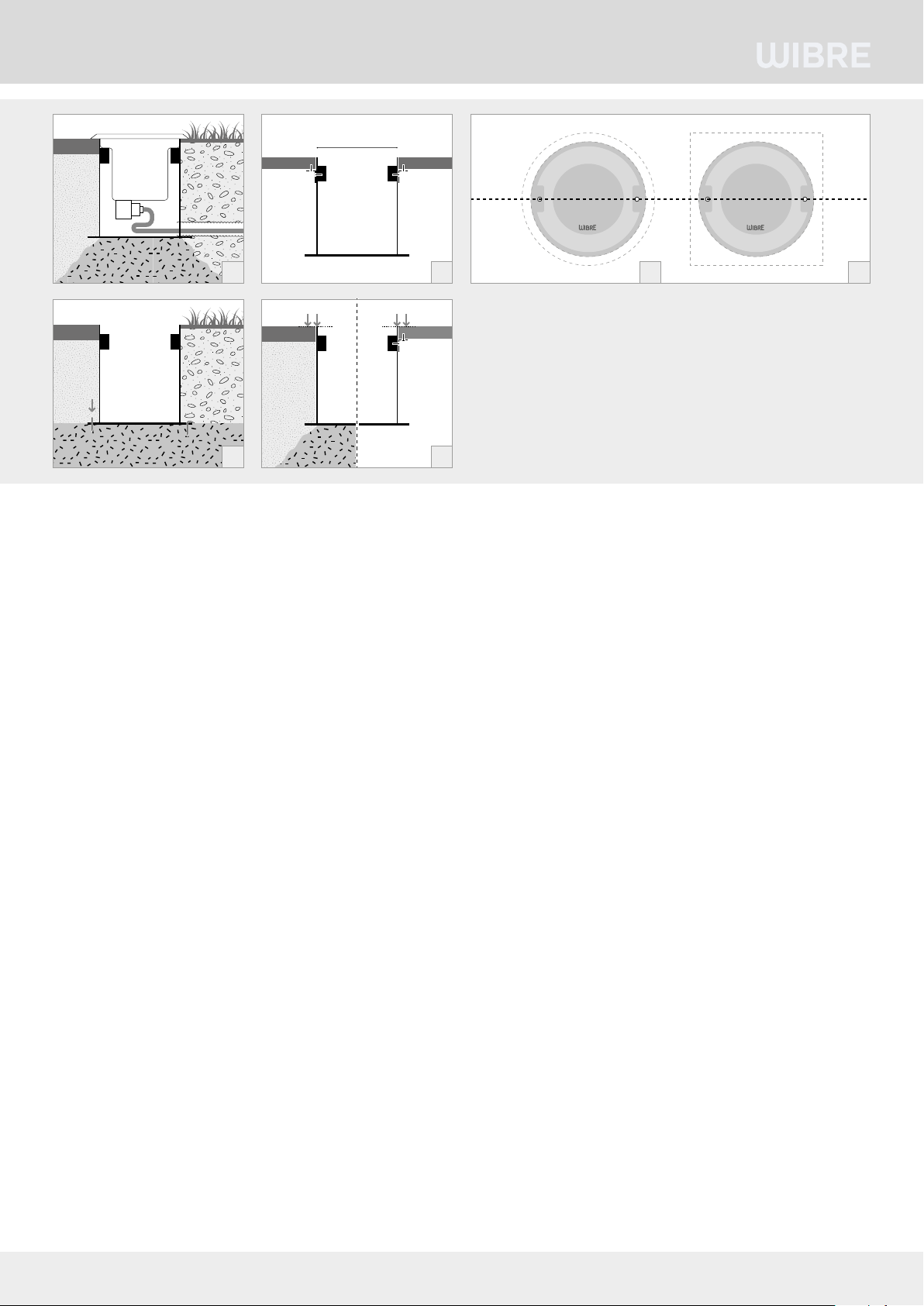
3.1./3.2. Einbau mittels Kunststoffeinbaugehäuse in Beton,
Asphalt, Erde o.ä.
3.3. Einbau mittels Kunststoffeinbaugehäuse in dünnwandige
Systeme o.ä.
Montage
Bei Einbau mit Kunststoffeinbaugehäuse in Beton, Asphalt oder
Erde sollte für eine sichere Standfestigkeit der Einbauhülse gege-
benenfalls ein Fundament vorgesehen werden und für ausreichende
Drainage z.B. durch Kiesauffüllung/Sand gesorgt werden.
Gegebenenfalls können die seitlichen Löcher am Boden des Einbau-
gehäuse zur Fixierung oder Ausrichtung eingesetzt werden. 3.2.
Bei Einbau mit Kunststoffeinbaugehäuse inWände oder dünn-
wandige Systeme sollte mit einem Schneidewerkzeug eine Öffnung
von D100 mm vorgesehen werden und das Einbaugehäuse mittels
den Haltewinkeln fixiert werden. 3.3.
Achtung: Für spätere Montage des Scheinwerfers muss die Ober-
kante Einbaugehäuse mit der Oberkante Abschlussfläche
(z.B. Boden, Fliese, Holz) bündig sein. 3.4.
Für gewünschte horizontale bzw. vertikale Ausrichtung der Leuchte
ist unbedingt auf eine korrekte Fixierung des Einbaugehäuses und
Ausrichtung der Schraublöcher für den späteren Scheinwerfereinbau
zu achten. 3.5./3.6.
3. Installation/mounting
When installing, observe the national safety regulations. We are not liable
for any improper use or installation. No liability will be accepted in case of
subsequent modification to the lights.
POW-LED lights must always be operated in series with appropriate
constant-current power sources (see operating devices) (350 mA).
The light housings must not be removed, since the cable and POW LED
printed circuit board are covered with waterproofing for protection.
Installation of the spotlight is possible in concrete, pavement, slabs,
wooden floor boards, soil, gravel, lawn or garden beds. Since ground
conditions and installation circumstances vary, no general installation
instructions can be provided.The icons symbolise typical installation
examples.
3.1./3.2. Installation using plastic installation housing in concrete,
asphalt, soil, or the like.
3.3. Installation using plastic installation housing in thin-walled systems
or the like.
Installation
For installation with plastic installation housing in concrete, asphalt or soil,
a foundation as well as sufficient drainage, e.g. with gravel/sand filling,
might be needed for secure stability of the installation sleeve.
If necessary, the holes in the bottom of the built-in pot can be used to fix or
adjust the spotlight. 3.2.
For installation with plastic installation housing in walls or thin-walled
systems, an hole d100 mm should be cut with a cutting tool and fixed with
the brackets. 3.3.
For tightness and later installation of the spotlight, the upper edge of the
installation housing must be flush with the upper edge of the top layer
surface (e.g. ground, tile, wood). 3.4.
To be able to align the light horizontally or vertically, as desired, attention
must always be paid to correct fixing of the installation housing and
alignment of the screw holes for later spotlight installation. 3.5./3.6.
3. Installation/Montage
Respecter les prescriptions nationales applicables en matière de sécurité.
Nous déclinons toute responsabilité pour l’utilisation ou le montage non
conforme. De même, nous réfutons toute responsabilité pour les modifi-
cations réalisées sur les luminaires.
Pour leur exploitation, les projecteurs à POW-LED doivent toujours être reliés
en série au bloc d‘alimentation en courant continu correspondant (voir blocs
d‘alimentation) (350 mA).
Ne pas démonter les boîtiers de projecteur, étant donné que les câbles et la
platine POW LED sont scellés.
Montage du projecteur dans le béton, les pavés, les plaques, les lames de
bois, la terre, le gravier, les espaces verts ou les plates-bandes. Étant donné
que dans les différents projets, les conditions du sol ainsi que la situation
d’intégration varient, nous ne pouvons établir une notice de montage
générale. Les pictogrammes expliquent les exemples de montage type.
3.1./3.2. Montage avec boîtier d‘encastrement en plastique dans le
béton, l‘asphalte, la terre, entre autres.
3.3. Montage avec boîtier d‘encastrement en plastique dans des
constructions à parois fines, entre autres.
Montage
Lors du montage avec boîtier d‘encastrement en plastique
dans le béton, l‘asphalte ou la terre, il est recommandé de prévoir le cas
échéant une fondation afin de garantir une bonne stabilité du tube de
montage et d‘assurer un drainage suffisant, par ex. par un remplissage de
gravier/sable.
Le cas échéant, utiliser les trous du fond de pot d’encastrement pour la
fixation ou le positionnement. 3.2.
Lors du montage avec boîtier d‘encastrement en plastique dans les murs ou
les constructions à parois fines prévoir avec des outils de coupe un trou de
diamètre. 100 mm et monter le pot d’encastrement avec l’aide de l’étrier de
fixation. 3.3
Pour l’étanchéité et le montage a posteriori du projecteur, le bord supérieur
du boîtier d‘encastrement doit affleurer avec la surface de finition
(p. ex. Le sol, les carreaux, le bois). 3.4.
Afin d‘assurer l‘alignement horizontal et vertical souhaité du projecteur,
veiller impérativement à une bonne fixation du boîtier d‘encastrement et
à un alignement approprié des trous de vis pour le montage ultérieur du
projecteur. 3.5./3.6.
2/4 WIBRE Elektrogeräte Edmund Breuninger GmbH & Co. KG · Liebigstrasse 9 · 74211 Leingarten/Germany
Telefon: +49 (0) 7131 9053-0 · Telefax: +49 (0) 7131 9053-19 · E-Mail: [email protected]
ø 100
3.1
3.2
3.3 3.5 3.6
3.4
INSTALLATION · MANUAL
Attention: Use only cable connected at the factory. Specify desired
cable length when ordering. Because of mechanical load, the cable should
also be laid in a protective tube.
The silicone cable should be connected to the mains supply under dry
conditions, or special connection units with sealing compound are to be
used if connected in the soil. (e.g. WIBRE article no. 9.9010.68.16)
Electrically connect individual wires to the power supply according to
regulations. 3.7.
The maximum number of lights can be taken from the power supply
manual. 3.8.
Fixing of the Spotlight
Place the light into the installation sleeve, insert approx. 0.5 m of cable into
the housing, and tighten the screws until the housing is flush with the top
edge of the final surface.
4. Connection to power units/ connection
matrix
Spotlights with POW-LED units may only be connected in series. 3.8.
If necessary. make the serial connection in a separate distribution box,
which outside must also be protected against moisture with sealing
compound.
5. General service information
-When cleaning, make sure that the lights do not come into contact with
metal-corroding cleaning agents.The use of cleaning agents containing
hydrochloric acid on and near spotlight parts made of stainless steel must
always be avoided.
- Clean spotlights and installation housing regularly to avoid extraneous
rust deposits.
- Attention: Do not use high-pressure cleaners.
- Attention: Protect lightbulbs from freezing; they must be removed,
if necessary, or specially protected.
- Lost screws may only be replaced by screws made of V4A.
- Depending on load (wattage, external conditions), we recommend
changing the seals (on the glass pane, screws, O-ring) and cable every
5–8 years.
Attention: utiliser uniquement les câbles raccordés en usine. Indiquer
la longueur de câble souhaitée lors de la commande. En cas de sollicitation
mécanique, le câble doit être posé dans une gaine de protection.
Le raccordement du câble en silicone au secteur doit être réalisé en milieu sec
et, dans le cas d‘un raccordement direct dans le sol, il convient d’utiliser des
unités de raccordement spéciales à masse de scellement. (par ex. WIBRE Réf.
9.9010.68.16)
Raccorder les différents conducteurs aux blocs d‘alimentation conformément
aux prescriptions. 3.7.
Le nombre maximal de projecteurs pouvant être reliés est indiqué dans le
manuel du bloc d‘alimentation 3.8.
Fixation du Projecteur
Mettre le projecteur en place dans le tube de montage, placer env. 0,5 m
de câble dans le boîtier et le visser jusqu‘à affleurement avec la surface de
finition.
4. Raccordement aux blocs d‘alimentation/
Matrice de raccordement
Les projecteurs à POW-LED doivent uniquement être raccordés en série. 3.8.
Le cas échéant, procéder au raccordement en série dans des boîtiers répar-
titeurs séparés dont l‘extérieur doit en outre être protégé contre l‘humidité à
l‘aide d‘une masse de scellement.
5. Instructions d‘entretien générales
- Lors du nettoyage, le projecteur ne doit pas entrer en contact avec des
détergents agressifs contre les métaux. L‘utilisation de détergent à base
d‘acide chlorhydrique sur et à proximité des pièces du projecteur en acier
inoxydable est totalement interdite.
- Nettoyer régulièrement le projecteur et le boîtier de montage afin d‘éviter
tout dépôt d‘oxydation.
- Attention: ne pas utiliser de nettoyeur haute pression.
- Attention: Protéger les projecteurs contre le gel ; le cas échéant, les
démonter ou assurer une protection spéciale.
- Les vis perdues ne doivent être remplacées que par des vis en acier
inoxydable V4A.
- Selon la sollicitation (puissance, circonstances environnementales), il est
recommandé de procéder au changement des joints (sur les vitres, les
raccords vissés et les joints toriques) et du câble tous les 5 à 8 ans.
WIBRE Elektrogeräte Edmund Breuninger GmbH & Co. KG · Liebigstrasse 9 · 74211 Leingarten/Germany
Telefon: +49 (0) 7131 9053-0 · Telefax: +49 (0) 7131 9053-19 · E-Mail: [email protected] 3/4
rot/red
schwarz/
black
+
–
+
–
sec
Netzteil
Ballast
Alimentation
3.7
3 POW-LED 350 mA
max 100 m
secprim
MAX21
braun/brown/brun
blau/blue/bleu
3 POW-LED RGB 350 mA MAXMIN
max 100 m
POW-LED
POW-LED
POW-LED
CH3CH2CH1
–
+
–
+
–
+rot/red/rouge
grün/green
/vert
blau/blue/bleu
weiß/white/blanc (we)
rot/red/rouge (rt)
schwarz/black/noir (sw)
grün/green/vert (gg)
gelb/yellow/jaune (ge)
blau/blue/bleu (bl)
3.8
3.8
Achtung: Nur werkseitig angeschlossenes Kabel verwenden.
Gewünschte Kabellänge bei Bestellung angeben.Wegen
mechanischer Beanspruchung sollte das Kabel zusätzlich in einem
Schutzrohr verlegt werden.
Der Anschluss des Silikonkabels an das Hauptnetz sollte im
Trockenen erfolgen bzw. bei Anschluss direkt im Erdreich sind
spezielle Anschlusseinheiten mitVergussmasse zu verwenden.
(z.B.WIBRE Art.Nr. 9.9010.68.16)
Einzelanschlussader entsprechend den Vorschriften an den Netz-
teilen elektrisch anschließen. 3.7.
Die maximale Anzahl der Leuchten sind dem Manual des Netzteiles
zu entnehmen. 3.8.
Montage des Scheinwerfers
Die Leuchte in die Einbauhülse einsetzen, ca. 0,5 m Kabel in das
Gehäuse einlegen und bis auf Oberkante der Abschlussfläche
einschrauben.
4. Anschluß an Netzteile/Anschlußmatrix
Scheinwerfer mit POW-LED Einheiten sind nur in Reihe anzu-
schließen. 3.8.
Gegebenenfalls Reihenanschluß in separaterVerteilerbox vor-
nehmen, die im Außenbereich zusätzlich mitVergußmasse gegen
Feuchtigkeit schützen.
5. Allgemeine Wartungshinweise
- Beim Reinigen darf die Leuchte nicht mit Metall angreifenden
Reinigungsmitteln in Berührung kommen. Der Einsatz salzsäure-
haltiger Reinigungsmittel an und in der Nähe von Scheinwerfer-
teilen aus Edelstahl ist in jedem Fall zu unterlassen.
- Scheinwerfer und Einbaugehäuse regelmäßig reinigen,
um Fremdrostablagerungen zu vermeiden.
-Achtung: Keine Hochdruckreiniger verwenden.
- Achtung: Strahler vor Einfrieren schützen, gegebenenfalls
müssen diese demontiert oder speziell geschützt werden.
-Verloren gegangene Schrauben dürfen nur durch Schrauben aus
V4A ersetzt werden.
- Je nach Beanspruchung (Höhe der Watttage, äußere Umstände) ist
alle 5–8 Jahre einWechsel der Dichtungen (Glasscheibe, Verschrau-
bung, O-Ring) und der Kabel zu empfehlen.
Hinweis: Reihenverschaltung bauseits
Reference: Serial connection made on site
Référence: connexion en série a fairre sur place
INSTALLATION · MANUAL
4/4 WIBRE Elektrogeräte Edmund Breuninger GmbH & Co. KG · Liebigstrasse 9 · 74211 Leingarten/Germany
Telefon: +49 (0) 7131 9053-0 · Telefax: +49 (0) 7131 9053-19 · E-Mail: [email protected]
6. Garantiebestimmungen
Unsere Garantiebedingungen finden Sie auf der jeweiligen
Garantiekarte des Produkts und unter wibre.de/warranty.
6. Warranty conditions
Our warranty conditions can be found on the respective warranty
card for the product and at wibre.de/warranty.
6. Conditions de garantie
Nos conditions de garantie se trouvent sur la carte de garantie
correspondante du produit et sous wibre.de/warranty.
W267 Stand 08.20 - Technische Änderungen vorbehalten - Für Druckfehler übernehmen wir keine Haftung
5. Wichtige Hinweise
(Bei Nichtbeachtung folgender Punkte,
entfällt die Garantie.)
•Vor der Installation müssen alleTeile auf Transportschäden
überprüft werden!
• Jegliche Montage-, Installations- und Elektroarbeiten müssen von
qualifiziertem Fachpersonal durchgeführt werden.
• ZurVermeidung von Gefährdungen darf eine beschädigte äußere
flixible Leitung dieser Leuchte ausschließlich vom Hersteller,
seinem Servicevertreter oder einer vergleichbaren Fachkraft
ausgetauscht werden.
• Die Lichtquelle dieser Leuchte darf nur vom Hersteller oder einem
von ihm beauftragten Servicetechniker oder einer vergleichbar
qualifizierten Person ersetzt werden.
• ZurVermeidung von Fremdrost nur Edelstahlwerkzeug verwenden!
• Die Kabellänge der Leuchten ist so zu wählen, dass man nicht im
Wasser oder feuchten Umgebung verlängern muss. Spätere Rekla-
mationen aufgrund dessen können nicht akzeptiert werden.
• Es dürfen nur originale Wibre-Betriebsgeräte verwendet werden.
• Ein Montageabstand von 10 cm zwischen Betriebsgeräten wird
dringend empfohlen, um wechselseitiges Erhitzen zu vermeiden.
• Anschluss der Betriebsgeräte muss stromlos erfolgen, da sonst
Entladungen im Netzteil zur Schädigung der LED führen können.
Es darf keine Primärspannung beim Wechsel der LED anliegen.
• Beim Anschließen der Leuchte die Polung beachten! Eine falsche
Polung kann dem LED-Modul schaden.
• Die Installation eines bauseitigen Überspannungsschutzes nach
DINVDE 0100-443, DINVDE 0100-534 und EN 62305 wird
empfohlen.
• Bitte achten Sie auf Maßnahmen gegen ESD (Elektrostatische
Entladung) während aller Arbeiten am Scheinwerfer, Betriebsgerät
und LED.
5. Important information
(If the following points are disregarded,
the guarantee expires.)
• Before installation, all parts must be checked for transport damage!
• All fitting, installation and electrical work must be performed by
qualified specialist staff.
•To avoid any hazards, a damaged external flexible cable of this
luminaire should only be replaced by the manufacturer, his service
representative or a comparable specialist.
•The light source of this luminaire may only be replaced by the
manufacturer or a service technician appointed by him or a compa-
rably qualified person.
• Only use stainless steel tools to avoid external rust!
•The cable length of the lights should be chosen in such a way that
it is not necessary to extend in water or moist environments. Later
complaints resulting from this cannot be accepted.
• Only original Wibre operating units may be used.
• An installation distance of 10 cm between operating devices is
urgently recommended in order to avoid mutual heating up.
•The operating devices must be connected without power, as
otherwise discharges in the power supply may cause the LED to
be damaged. No primary voltage may be applied when changing
the LED.
• Note polarity when changing the lights!The wrong polarity can
damage the LED module.
• It is recommended that the customer install an overvoltage pro-
tection in accordance with DINVDE 0100-443, DIN VDE 0100-534
and EN 62305.
• Please comply with all anti-ESD (electrostatic discharge) measures
during all work on the spotlight, operating device and LED.
5. Remarques importantes
(La garantie s‘éteint en cas de non-respect
des points suivants)
• L‘absence d‘avaries de transport doit être vérifiée avant
l‘installation !
•Tous les travaux de montage et d‘installation, ainsi que les travaux
électriques, doivent être réalisés par du personnel qualifié.
• Pour éviter tout danger, un câble flexible externe endommagé du
projecteur ne peut être remplacé que par le fabricant, son représen-
tant de service ou un spécialiste qualifié.
• La source lumineuse de ce liminaire ne peut être remplacée que par
le fabricant ou un technicien de service désigné par lui ou par une
personne ayant une qualification comparable.
• Afin d‘éviter tout dépôt de rouille, utiliser exclusivement des outils
en acier inoxydable !
• La longueur de câble des lampes doit être choisie de telle sorte à ce
qu‘il ne soit pas nécessaire de la prolonger dans de l‘eau ou dans un
environnement humide. Toute réclamation ultérieure à ce motif ne
sera pas acceptée.
• Seuls des équipementsWibre originaux doivent être utilisés.
• Une distance de montage de 10 cm entre les équipements est
vivement recommandée afin d‘éviter un réchauffement mutuel.
• Le raccordement des équipements doit être effectué sans courant,
sans quoi des décharges dans le bloc d‘alimentation pourraient
entraîner une détérioration des LED. Aucune tension primaire ne
doit être établie lors du changement des LED.
• Lors du raccordement des lampes, respecter la polarité ! Une erreur
de polarité peut endommager le module de LED.
• L‘installation d‘une protection contre la surtension par le client
conforme aux normes DINVDE 0100-443, DIN VDE 0100-534 et EN
62305 est recommandée.
•Veuillez respecter les mesures contre la décharge électrostatique
durant tous les travaux sur des projecteurs, équipements et LED.

Other Wibre Outdoor Light manuals

Wibre 4.0314 User manual

Wibre

Wibre 4.0314 User manual

Wibre 4.0010 User manual

Wibre

Wibre 4.0010 User manual

Wibre 4.0100 User manual

Wibre

Wibre 4.0100 User manual

Wibre 4.0050 User manual

Wibre

Wibre 4.0050 User manual

Popular Outdoor Light manuals by other brands

PANA ET-LAD510C operating instructions

PANA

PANA ET-LAD510C operating instructions

WE-EF EFL540 LED Installation and maintenance instructions

WE-EF

WE-EF EFL540 LED Installation and maintenance instructions

Health Zenith SL-4110 Installation and operating instructions

Health Zenith

Health Zenith SL-4110 Installation and operating instructions

OBI Sassano 312057 instruction manual

OBI

OBI Sassano 312057 instruction manual

LIGMAN VA-20023-LC installation manual

LIGMAN

LIGMAN VA-20023-LC installation manual

RL R460410 Series quick start guide

RL

RL R460410 Series quick start guide

Sunnydaze Decor INA-385 manual

Sunnydaze Decor

Sunnydaze Decor INA-385 manual

Hess MADRID Installation and operating instructions

Hess

Hess MADRID Installation and operating instructions

WAC Lighting dweLED 649 Series installation instructions

WAC Lighting

WAC Lighting dweLED 649 Series installation instructions

kim lighting Lightvault RGBW LTV81 installation instructions

kim lighting

kim lighting Lightvault RGBW LTV81 installation instructions

furniture123 DMM002 user manual

furniture123

furniture123 DMM002 user manual

Henn&Hart FL0425 instructions

Henn&Hart

Henn&Hart FL0425 instructions

Saxby Lighting Odyssey ST5008BK installation instructions

Saxby Lighting

Saxby Lighting Odyssey ST5008BK installation instructions

LIGMAN ZA-20001 installation manual

LIGMAN

LIGMAN ZA-20001 installation manual

LUCCI OSBORNE DAY NIGHT SLEEP PLUS installation instructions

LUCCI

LUCCI OSBORNE DAY NIGHT SLEEP PLUS installation instructions

LIGMAN BIU-90044-LC installation manual

LIGMAN

LIGMAN BIU-90044-LC installation manual

atmosphera Bren manual

atmosphera

atmosphera Bren manual

Gama Sonic 94BM500D2 instruction manual

Gama Sonic

Gama Sonic 94BM500D2 instruction manual

manuals.online logo
manuals.online logoBrands
  • About & Mission
  • Contact us
  • Privacy Policy
  • Terms and Conditions

Copyright 2025 Manuals.Online. All Rights Reserved.