Widearea AER800-24P User manual

Widearea Telecommunication Technology Co., Ltd
Add: 2nd,3rd East Round Longtan Industry Garden 10#,Chengdu, Sichuan, China
Tel: (86)28 84207501 (86)28 84207506 Fax: (86)28 84209696
E-mail: master@widearea.com.cn Web Site: http://www.widearea.com.cn
ADSL Loop Extender
(AER800-24P)
Installation Manual
Version: 001
Please read this
document carefully
before installation!

ADSL Loop Extender Installation Manual Page 1
This publication may neither be reproduced in whole nor in part without the express written
permission of Widearea.
Preface
This manual provides information on how to best use this product. Please read
this manual thoroughly before installation and use. Additionally, please keep
this manual handy for ease of reference during installation and troubleshooting.
The contents of this document may be updated in the future, without prior
notice.
This booklet was created with thorough attention to the content. If,
however, you have a question, spot an error, or find a description lacking, please
refer to the end of this booklet for information on how to contact us.
All brand names and trademarks are the property of their respective
owners.

ADSL Loop Extender Installation Manual Page 2
This publication may neither be reproduced in whole nor in part without the express written
permission of Widearea.
Contents
1. General Description............................................................................................ 3
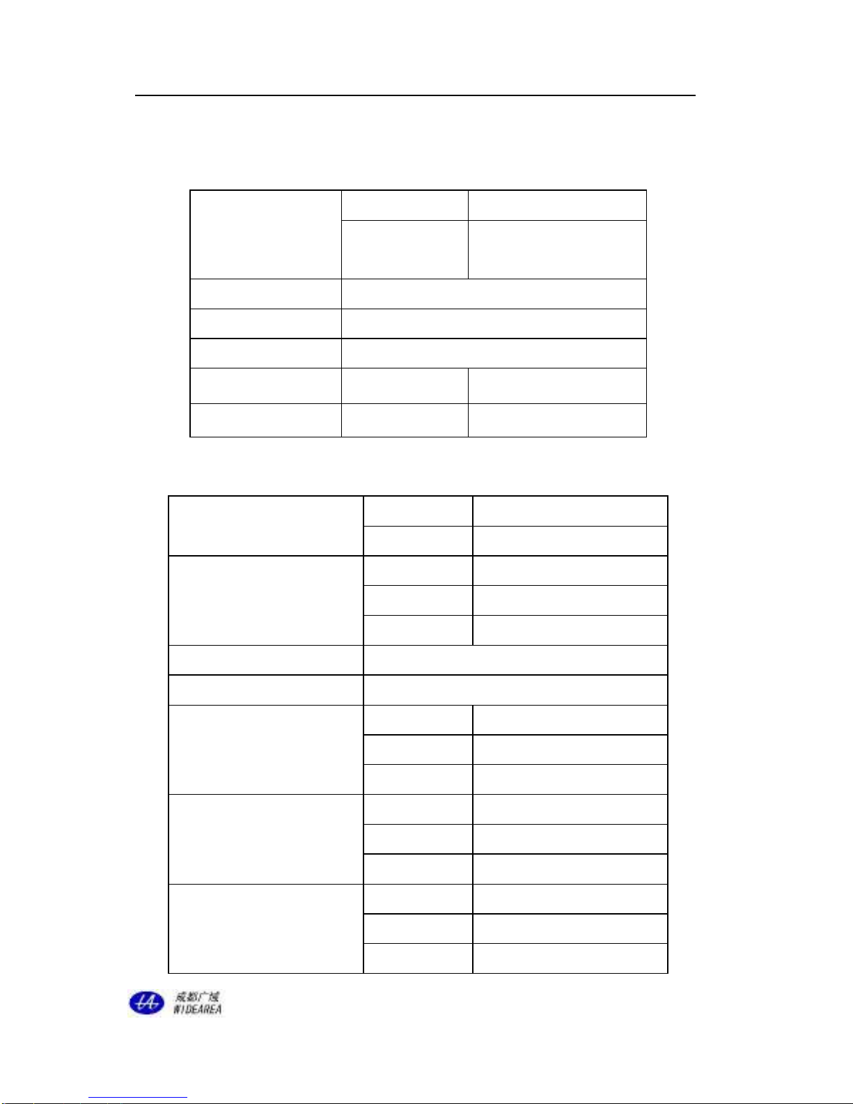
2. Technical Specifications..................................................................................... 4
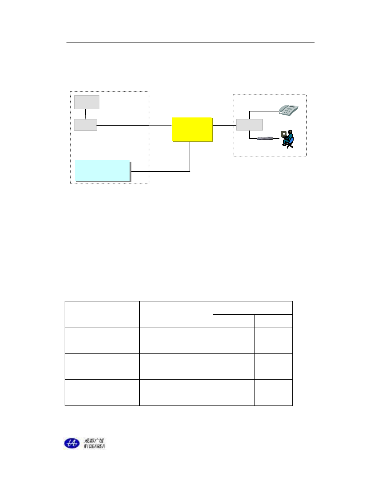
3. Application......................................................................................................... 4
3.1 The Real Lines Connection of Equipment............................................... 5
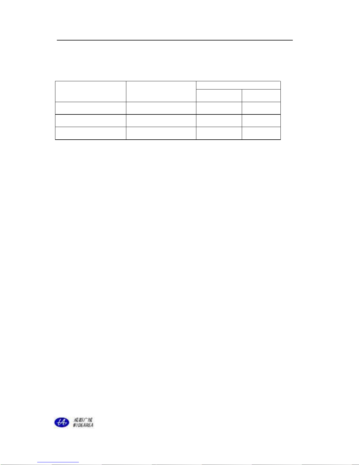
3.2 Resistance and Length Demand .............................................................. 5
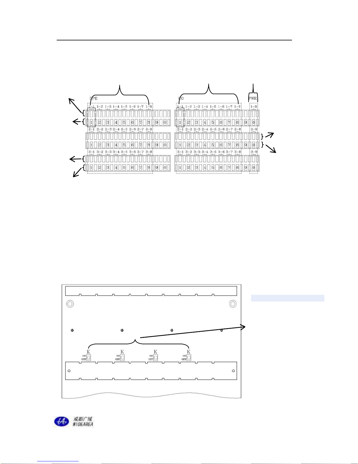
4. Products Structure .............................................................................................. 6
4.1 AER800-24P ADSL Loop Extender........................................................ 7
4.1.1 AER800-24P..................................................................................... 7
4.1.2 Extender card AER800-C1P........................................................... 10
4.1.3 Power card AER800-PWR ............................................................. 10
4.2 AEC Power supply Series.......................................................................11
4.2.1 AEC-B1P.........................................................................................11
4.2.2 AEC-B4P.........................................................................................11
4.2.3AEC-RACK ................................................................................... 12
5. Installation Procedure....................................................................................... 14
5.1 Unpack .................................................................................................. 14
5.2 Install the Power Supply Equipment ..................................................... 14
5.3 Install the ADSL Loop Extender ........................................................... 15
6. Troubleshooting................................................................................................ 16

ADSL Loop Extender Installation Manual Page 3
This publication may neither be reproduced in whole nor in part without the express written
permission of Widearea.
1. General Description
The ADSL Loop Extender expands the coverage of ADSL lines. It will provide systems with a
higher performance-to-cost ratio, improve equipment utilization rates, and optimize the network.
This product will allow you to double the number of subscribers that you can reach while
offering a more consistent high bandwidth service to your existing customers.
The ADSL Loop Extender is an active element installed in the outside loop plant. It operates
as an amplifier and equalizes the signal.
The new generations of line powered ADSL Loop Extenders consist of an enclosure and card
system designed to offer a modular deployment option. The parts list is detailed below:
AER800-24P Box: A Box for 24 AER800-C1P cards and 3 AER800-PWR cards, which
are divided into 3 independent sub-systems.
AER800-C1P: A one port ADSL Loop Extender designed to be inserted into the
backplane of the AER800-24P enclosure.
AER800-PWR: One port Power Supply, which can power 1~8 AER800-C1P cards, and
can be inserted into the AER800-24P.
Benefits
Additional ADSL subscriberscan be added by inserting AER800-C1P cards.
Only one additional power pairs can power 1~8 AER800-C1P cards.
Comprehensive over-voltage protection.
Easy to install, deploy, and maintain.
Low power consumption.

ADSL Loop Extender Installation Manual Page 4
This publication may neither be reproduced in whole nor in part without the express written
permission of Widearea.
2. Technical Specifications
Table 1 –Technical Specifications of AER800-24P
Operating
Environment
Temperature
-40℃~+65℃
Relative
Humidity
5% ~95%
(Non-condensing)
Input Voltage
DC60V~DC122V
Power Consumption
Less than 0.2W( per port )
Max. Output Current
Less than 18mA for each power card (for eight ports )
Dimension(LWH)
AER800-24P Box
662mm×362mm×94mm
Supported Subscribers
AER800-24P
24 ADSL subscribers
Table 2 - Technical Specifications of AEC-B1P/B4P/RACK
Operating Environment
Temperature
-10℃~+45℃
Relative Humidity
5%~95% (Non-condensing)
Input Voltage
AEC-B1P
AC 110V/ AC220V or DC -48V
AEC-B4P
DC -48V
AEC-RACK
DC -48V
Output Voltage
DC 116V
Max. Output Current
Less than 50mA
Output Port
AEC-B1P
1Port
AEC-B4P
4Port
AEC-RACK
2×13Port(MAX)
Supported quantity of AER800-C1P
AEC-B1P
8 AER800-C1P
AEC-B4P
32 AER800-C1P
AEC-RACK
208 AER800-C1P
Dimension(LWH)
AEC-B1P
110×50×30mm
AEC-B4P
480×160×44mm
AEC-RACK
485×153×133mm

ADSL Loop Extender Installation Manual Page 5
This publication may neither be reproduced in whole nor in part without the express written
permission of Widearea.
3. Application
3.1 Equipment connection diagram:
Figure 1 ADSL Loop ExtenderApplication Diagram
L1: The signal twisted-pair connecting the AER800-C1P to the DSLAM.
L2: The signal twisted-pair connecting the AER800-C1P to the Modem.
L3: Power supply twisted-pair sending DC116V to the AER800-PWR card.
3.2 Resistance and Length Demand
The recommended installation conditions are as follows:
(1)26 AWG (0.4mm) twisted-pair
Table 3 -The demand of loop resistance and length
Route
Loop Resistance
(Ohms)
length
K feet
Km
L1(CO-Extender)
415 ~ 1240
4.9 ~
14.8
1.5 ~
4.5
L2(Extender-CPE)
83 ~ 1100
1.0 ~
13.0
0.3 ~
4.0
L(CO-Extender-CPE)
635 ~ 1660
7.5 ~
19.7
2.3 ~
6.0
Modem
CPE
L2
ADSL+POTS
ADSL
L3
Power Supply
L1
ADSL+POTS
ADSL Loop Extender
Power Supply
DSLAM
Switch
POTS
CO
ADSL
Loop Extender
splitter

ADSL Loop Extender Installation Manual Page 6
This publication may neither be reproduced in whole nor in part without the express written
permission of Widearea.
(2)24 AWG(0.5mm) twisted-pair
Table 4 -The demand of resistance and length
Route
Loop Resistance
(Ohms)
Length
K feet
Km
L1(CO-Extender)
345 ~ 1030
6.6 ~ 19.7
2.0 ~ 6.0
L2(Extender-CPE)
52 ~ 929
1.0 ~ 17.7
0.3 ~ 5.4
L(CO-Extender-CPE)
570 ~ 1449
10.8 ~ 27.6
3.3 ~ 8.4
4. Products Structure
AER800-24P Box: Enclosure for 24 AER800-C1P cards and 3 AER800-PWR cards.
AER800-C1P: A one port ADSL Loop Extender designed to be inserted into the
AER800-24P
AER800-PWR: Provides power for 1~8 AER800-C1P cards.

ADSL Loop Extender Installation Manual Page 7
This publication may neither be reproduced in whole nor in part without the express written
permission of Widearea.
4.1 AER800-24PADSL Loop Extender
Figure 1 AER800-24P Overview
AER800-PWR Cards
Modular card slots
Terminal Area
Card Area
Ground Terminal
CPE Cable Gland
LED Power Indicator
CO Cable Gland

ADSL Loop Extender Installation Manual Page 8
This publication may neither be reproduced in whole nor in part without the express written
permission of Widearea.
Figure 2 AER800-24PTerminals Area
According to the connection diagram on the back of the door, terminals are connected to the
card with the same code internally. Through the internal pairs, Extender cards are connected to
the internal terminal. CO and CPE cables should be connected to external terminals.
Note: When inserting Line Power Extender Cards, 1-9 / 2-9 / 3-9 slots can be used for
additionalAER800-C1PLcards, allowing for a total of 27 subscribers.
CPE Terminals
Power Supply
Input Terminal
Extender Card Power Switch.
To turn on the individual
Extender cards, make sure
each switch is set to ON. Each
card has a corresponding
power switch directly beneath
the slot.
CO Terminals
The First External
Terminals Row
The Third External
Terminals Row
The Second External
Terminals Row
The First Internal
Terminals Row
The Third Internal
Terminals Row
The Second Internal
Terminals Row

ADSL Loop Extender Installation Manual Page 9
This publication may neither be reproduced in whole nor in part without the express written
permission of Widearea.
Figure 5 AER800-24P Cards Area
Table 5- The Corresponding of K Switch
Switch Bit
AER800-C1P Card
K1
1-1,1-2
K2
1-3,1-4
K3
1-5,1-6
K4
1-7,1-8
K5
2-1,2-2
K6
2-3,2-4
K7
2-5,2-6
K8
2-7,2-8
K9
3-1,3-2
K10
3-3,3-4
K11
3-5,3-6
K12
3-7,3-8
4.1.2 Extender card AER800-C1P
AER800-C1P is the Extender card. LED light indicates power supply status.
4.1.3 Power card AER800-PWR
AER800-PWR is the power supply card, which receives remote power from the CO, after
conversion, it powers the AER800-C1P. The LED indicates that DC116V power has been
supplied.

ADSL Loop Extender Installation Manual Page 10
This publication may neither be reproduced in whole nor in part without the express written
permission of Widearea.
4.2 AEC Power Supply Series
4.2.1 AEC-B1P (1Port Output)
Figure 6 AEC-B1P
Output connector:
Figure.7 AEC-B1P Output Connector Wiring Diagram
4.2.2 AEC-B4P (4Port Output)
Figure 8 AEC-B4P Front View
Figure 9 AEC-B4P Back View
Power output switch
Power LED
DC Power Input Terminal
Power Supply Output Terminal
Ground Terminal

ADSL Loop Extender Installation Manual Page 11
This publication may neither be reproduced in whole nor in part without the express written
permission of Widearea.
Table 6- The Description of AEC-B4PTerminal
Terminal
Description
K11
PWR11
J1
First group and first output.
A11
B11
K12
PWR12
J2
First group and second output.
A12
B12
K21
PWR21
J3
Second group and first output.
A21
B21
K22
PWR22
J4
Second group and second output.
A22
B22
4.2.3 AEC-RACK (Maximum 2×13Port Output)
AEC-RACK is a rack for AEC-C2P cards. One rack contains slots for 13 cards.
AEC-C2P is a 2 port power supply for express powered ADSL Loop Extenders
(AER800-xP).
Figure 10 AEC-RACK Front View
Figure 11 AEC-RACK Back View
Power Supply Rack
Power Supply Card AEC- C2P
Power Output Switch
Power LED
DC Input Terminal
Standby DC Input Terminal
Ground Terminal

ADSL Loop Extender Installation Manual Page 12
This publication may neither be reproduced in whole nor in part without the express written
permission of Widearea.
Attention: Polarity of DC48V power input.
Table 7 –Technical Specifications of AEC-RACK, AEC-C2P
Operating Environment
Temperature
-10℃~+45℃
Relative Humidity
5%~95%
(Non-condensing)
Input Voltage
DC48V(36V~72V)
Output Voltage
DC 116V per port
Output Current
Less than 50mA
Fuse Rating
5A
Dimension of RACK
485mm(L)×153mm(W)×133mm(H)
Table 8- the Description of the AEC-RACK Terminal
Terminal
Description
K1
PWR1
J
First output
A1
B1
K2
PWR2
J
Second output.
A2
B2
Note: In this table, the “J”indicates any of the outlets “J1~J13”
In figure 11, you can input DC48V through the 2×3 cords “DC48V-I”. The “DC48V-II”is only
used in during factory testing. Additionally, the grounding screw is located in the lower right hand
corner. “COM ALM”In the upper left hand corner is only used for factory testing. The outlets
“J1~J13”are the DC116V output terminals. AEC-C2P cards can supply 2хDC116V which
allows a single card to power two lines.

ADSL Loop Extender Installation Manual Page 13
This publication may neither be reproduced in whole nor in part without the express written
permission of Widearea.
AEC-C2P
Figure 12 The Panel of AEC-C2P
In figure 12, the lights “PWR1”and “PWR2”indicate the status of the equipment. After the power
supply is connected, press the button “K1”and “K2”, and the corresponding PWR light should be
solid green. Flashing indicator indicates short circuits or over-current alarm condition.
5. Installation Procedure
5.1 Unpack
When unpacking the equipment, be sure to check the contents of the packaging for
completeness against your purchase order. Notify your supplier immediately if any items are
missing.
Note: Please save packing material. All equipment returned must be packed in the original
packing material.
Be sure to inspect the equipment for shipping damage, including bent or loose hardware, and
broken connectors. If the equipment appears to have been damaged in transit, please contact
your supplier.
5.2 Install the Power Supply
(1) Generally, the Power Supply is installed at the CO. Make sure the type of power supply you
ordered, AC85V~AC265V or DC48V is correct for your source voltage.
(2) Before installation, the DC 48V or AC85V~AC265V power supply must be reliably
grounded.
(3) The power supply can also be installed in the CPE or near the ALE, if CO installation is not

ADSL Loop Extender Installation Manual Page 14
This publication may neither be reproduced in whole nor in part without the express written
permission of Widearea.
feasible.
(4) If the ADSL Loop Extender is installed in a remote location without local power available,
an additional copper pair (L3 as shown in Fig. 1) is required for power. The supply voltage
will pass through the power converter and feed to this additional pair.
(5) The supplied accessories include a power cord for DC -48V. Connect it to the DC -48V power
source. Please connect the cord according to the polarization indicated.
(6) Remove about 10mm of insulation and insert the wire end into the connector matched with
the outlet and screw it down. Then insert the connector into the outlet. After that, connect
the signal cable, the signal cable is polarity independent.
Attention: 1.Please connect the ground terminal to reliable a ground. Copper-core wire
with no less than 2.5mm2(13 AWG) diameter is required as ground wire.
2. Power supply should NOT be turned on until the ALE installation is
finished.
3. When the power supply wire is active, do NOT operate the A and B wire of
the supply pair simultaneously. The A and B wire should be isolated.
5.3 Install the ADSL Loop Extender
(1) Install the AER800-24P Enclosure in the junction cabinet. Ground the Enclosure through the
grounding screw located on the bottom outside the Box.
Attention: Copper-core wire with no less than 2.5mm2(13 AWG) diameter is required as
ground wire. One end of the wire should connect to Loop Extender’s ground terminal.
The other end of the wire should connect to a reliable grounding point.
(2) Insert the power card AER800-PWR into the AER800-24P Box.
(3) Insert the Extender card AER800-C1P into the AER800-24P Box.
(4) Connect the cable according to the connection diagram.
Connect the power pair into the AER800-PWR card.
Connect the signal cable to the terminal area, the cable from the DSLAM connects to the
“CO”terminal, and the cable from the modem connects to the “CPE”terminal.
Attention: The Power Supply should NOT be turned on until the Extender installation is

ADSL Loop Extender Installation Manual Page 15
This publication may neither be reproduced in whole nor in part without the express written
permission of Widearea.
finished.
(5) Power on: after confirming that all the twisted-pair cables are connected correctly and the
Enclosure is securely installed, Then turn on the Extender card, please make sure Extender
card Power Switch is set to ON. After powering on the system the ADSL Loop Extender will
work within 10 seconds.
6. Troubleshooting
Table 5 - ADSL Loop Extender Troubleshooting
Problem Description
Possible Reason
Suggested Resolution
Equipment does not work after
connected. Status LED is OFF.
CO side cable is not
connected properly.
Check CO side cable.
No
connection
AER800-C1PL
status LED is on.
Cables at DSLAM or
Modem side are not
connected properly.
Correct the cable connection.
Line quality issues.
Diagnose cable for proper
Ohms/Attenuation values.
There is a telephone
before the splitter on
CPE side.
Discard the telephone before the
splitter on CPE side.
ADSL Loop
Extender is not
connected properly.
Correct the cable connection, or
check whether the distance between
the DSLAM, Extender, and Modem
is within recommended values.
L1 or L2 is too short.
Check that loop extender placement
meets engineering requirements.
SNR Margin is too
high.
Reduce SNR Margin setting on the
DSLAM until a connection is made.
We suggest using SNR Margin < 10.

ADSL Loop Extender Installation Manual Page 16
This publication may neither be reproduced in whole nor in part without the express written
permission of Widearea.
Testing with SNR margin = 1 can
provide useful hints during
troubleshooting.
There is noise on the user’s
telephone line.
CO/CPE cable is
connected to ground
or the wire insulation
is faulty.
Check the cables.
Possible
electromagnetic
interference.
Check to ensure the extender is not
located near any high voltage
equipment.
Internet is slow, frequent
disconnects.
Possible PC issues,
virus, hardware
malfunction, etc.
Verify issue with test set or a known
good piece of hardware. Check
statistics on modem and DSLAM.
Parallel open wire at
CPE is too long or
the connector is
rusted.
Change the parallel cable to copper
twisted-pair.
The CPE side cable
has too many
connectors.
Avoid exposed connectors, use good
quality cable.
SNR Margin too low.
Increase the SNR margin setting in
the DSLAM to 6 or more.
Bit Error Rate too
High.
Increase SNR Margin setting in the
DSLAM.
Data profile is too
high for this circuit.
Lower the minimum data rate in the
DSLAM.
Table of contents
Other Widearea Extender manuals