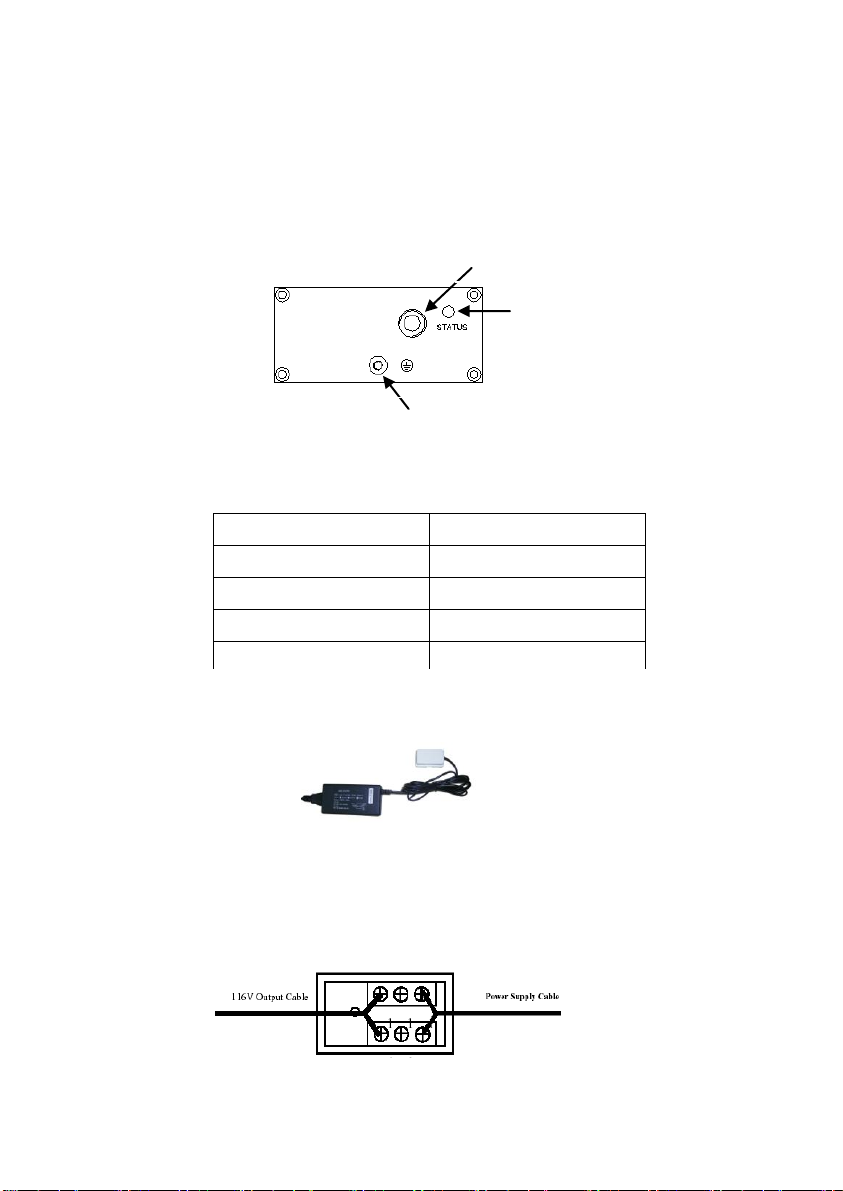
Figure 4 AEC-B1P connector wiring diagram
Installation Procedure
5.1 Unpack
Unpack equipment carefully, check for completeness against the purchase order. Notify the
supplier if items are missing.
Note: Save packing material. All equipment returned must be packed in the original
packing material.
Inspect equipment for shipping damage, including bent or loose hardware, and broken
connectors. If equipment was damaged in transit, contact the supplier.
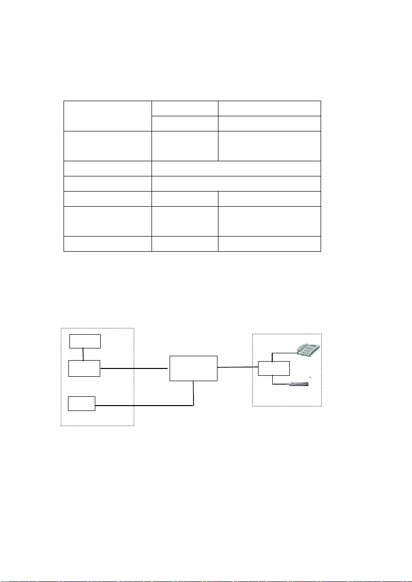
5.2 Install the remote power supply
Generally, the Power Supply is installed at CO side. The type of power supply ordered should
be right, either AC110V /AC220V or DC48V.
The Power supply also can be installed in the CPE or near the extender.
One Spare copper pair is needed for deliver power to VER-1P.
Before installation, the DC 48V or AC110V~AC220V power supply should be grounded
reliably.
DC 48V Power input is non-polarity.
The output of DC116V is non-polarity.
Attention:
1. Ground terminal should be grounded reliably. Copper-core wire with no less than 2.5mm2
section area is required as ground wire.
2. Remote power supply should not be turned on until the extenderinstallation is finished.
3. When the power supply wire is active, do not touch both two wires of the twist pair
simultaneously.
5.3 Install the VER
Fix the VER-1P box in the junction cabinet or near about at the supplied point. Ground the box
through the grounding screw in the bottom outside the box.
Attention: Copper-core wire with no less than 2.5mm2section area is required as ground