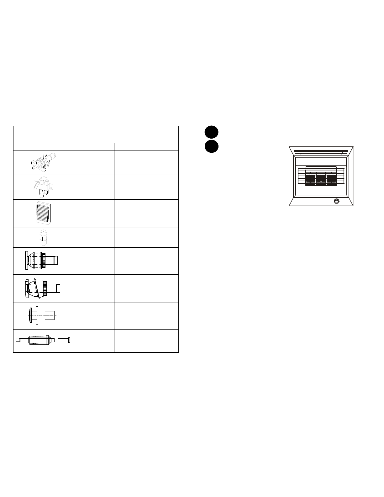
Widney Revo User manual

SHORT PARTS LIST
The illustrated short parts list includes part numbers.
When ordering quote gas fire name with part number & description.
Gas Train PART NUMBER DESCRIPTION
W00018
W00166 Control Valve with rotary ignition
(LPG)
Control Valve with rotary ignition
(NG)
W00020
W00170 Oxygen depletion device / pilot
assembly (LPG)
Oxygen depletion device / pilot
assembly (NG)
RA002 Radiant (pack of 3)
W00028
W00167
Burner Injector (LPG)
Burner Injector (NG)
W99901
Straight Terminal with Vent
Plain Finish.
For other finishes please contact
customer services
W99801
Angled Terminal with Vent.
Plain Finish.
For other finishes please contact
customer services
W99600
Straight Terminal Non Vented.
Plain Finish.
For other finishes please contact
customer services
W00213
Terminal with Vent
Pantile Roof
For other finishes please contact
customer services
8
Part Number: W00317 Issue E
GB
IE
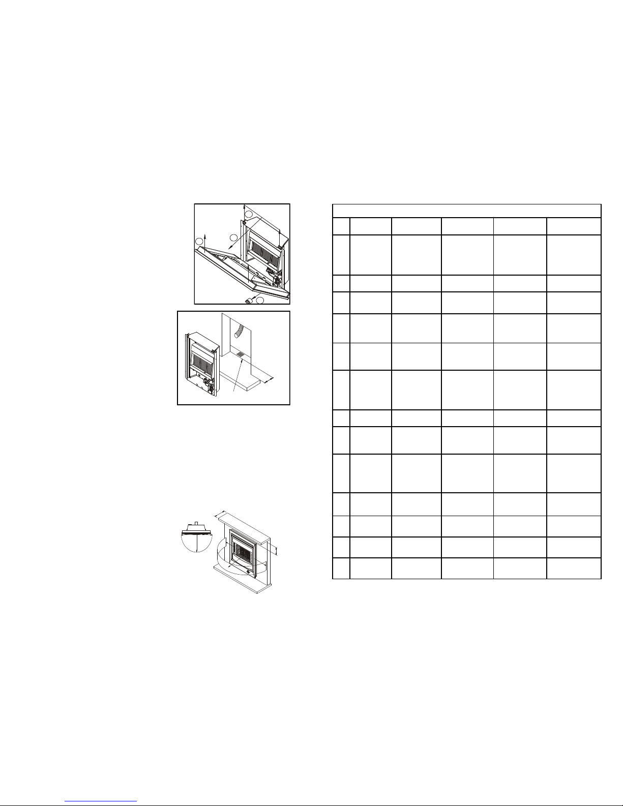
INSTALLATION & MAINTENANCE INSTRUCTIONS
READ THESE INSTRUCTIONS BEFORE INSTALLING OR SERVICING THE FIRE
IMPORTANT: Before installation ensure that the local distribution conditions (identified by
the type of gas and pressure) and the adjustment of the appliance are compatible.
Revo Natural gas version.
The appliance is suitable for use with G20 natural gas at a supply pressure of 20mbar for categories
I2H & I2E and additionally G25 at a supply pressure of 25mbar (pressure couple operates) in the case
of category I2E+& I2L.The following lists all EC member states, which have a suitable gas supply for
each category designation:
I2H:- AT, CH, CZ, DK, ES, FI, GB, GR, IE, IT, NO, PT, SE, EE, LT, LV, SI, SK
I2E:- DE, LU - I2E+:- BE, FR—I2L:- NL
Revo LPG gas version.
The appliance is suitable for use with G30 Butane at a supply pressure of 28-30 mbar and G31
Propane at a supply pressure of 37 mbar for category I 3+. It is also suitable for G30 Butane and
G31 Propane at a supply pressure of 30mbar for I 3B/P
The following lists all EC member states, which have a suitable gas supply for each category
designation:
I 3B/P:- CZ, FI, NL, NO, SE, LT, LV, SI, SK
I 3+:- BE, CH, CZ, ES, FR, GB, IE, IT, PT, EE, CY
It is a legal requirement that all gas appliances are installed by a competent person in accordance
with the Gas Safety Installation and Use Regulations 1994.
Failure to install the appliance as stated can lead to prosecution, it is in your interests
that the law is complied with.
Installation and Ventilation requirements shall be in accordance with these Installation Instructions,
BS EN 1949:2002, BS EN 721:1999, BS5871 and BS EN 1647:1999.
For the Republic of Ireland the installation must be carried out by a competent person and also conform to the relevant pa rts of :
The current edition of IS 813—Domestic Gas Installations
All relevant national and local rules in force
WIDNEY LEISURE LTD.
SAXON BUSINESS PARK, HANBURY ROAD,
STOKE PRIOR, BROMSGROVE,
WORCESTERSHIRE B60 4AD. ENGLAND
TELEPHONE: +44(0)1527 577800
Email: sales@widney-leisure.co.uk Web: www.widney-leisure.co.uk
1
WIDNEY
Revo
Gas Fire
All Model Variants

PREPARATION OF THE FIRE:
Note: Before commencing installation it is recommended that
you fill in the appliance details on the rear of the user’s
instruction.
REMOVAL OF THE FIRE FRONT:
Remove the control knob from the gas valve by pulling in the
direction of the arrow. Lift the front upwards approximately
10mm to clear the top location brackets taking care not to distort
or damage the top louvre vents
Pull the top of the front forward approximately 50mm then lift
clear of the locating tabs in the base of the fire. (See Fig 1)
REPLACING THE FIRE FRONT:
Reverse the above procedure taking care to locate the
upturned tabs on the base panel into the slots in the lower
panel return flange on the fire front.
LOCATION:
When locating the fire ensure that the minimum thermal lift of
1690mm as indicated in figure 4 can be achieved.
PREPARING THE APERTURE:
Cut an aperture in the furniture to the following
dimensions: 560mm High x 440mm Wide, this ensures a
minimum 5mm air gap between the fire back and the
furniture is maintained.
It is recommended that the base of the fire is supported
and no room air is allowed to enter the cavity from under
the fire base (See fig 2).
FITTING THE FIRE:
The fire must only be fitted with recommended flue liner and terminals - please consult the supplier for
further information. The flue liner needs to be prepared prior to fitting. Refer to these instructions and Fig 4
for this stage.
Depending on the construction of the flue cavity, the flue liner can be installed before or after the fire back is
fastened into position. In any installation, the flue liner must be pushed fully over the fire back flue spigot
and secured to the fire and Terminal spigot using steel self-tapping fasteners which will retain the liner into
full position to the terminal/fire spigots. Under no circumstances must the liner be left installed without a
sound connection and the position unfastened.
The fire should be installed as fig 3 with self tapping screws through the 2 fixing brackets on the sides of the
main fire chassis to the fire surround.
Any materials, coatings or finishes used in the construction of the fire surround and hearth must be
specified to tolerate the full radiated and convected and conducted heat from the fire.
POSITION OF COMBUSTIBLE MATERIALS:
It is recommended that no fixed combustible materials are
located within 500mm of the centre line of the fire –measured
from the centre radiant. Any combustible materials used for
the construction of the fireplace that are not subject to direct
line of sight to the ceramic radiants must be able to tolerate
the radiated, conducted and convected heat of the appliance
when operated at full rate. The materials used must comply
with the relevant British or EN standard / Code of Practice for
this installation. Note: It is the responsibility of the installer to
ensure that any material used adjacent to or adjoining the
appliance is fit for purpose. Any loose furnishings should not
be placed within the dimensions as indicated in (Figure 3)
1
2
3
4
Fig 1
Fig 2
Ensure that the Hearth
extends under the Fire
120mm
minimum
Fig 3
100mm
Maximum
100mm
Minimum
500mm
A 500mm line should be
taken from the centre of
the Fire Radiants to a part
500mm in front of the fire
500mm
2
7
WIDNEY LEISURE GAS FIRE TROUBLE SHOOTING TABLE
Fault Action I still have a
problem
Action I still have a
problem
1 Fire will Not
Ignite
Check gas pressure
at fire
If pressure is correct
see item2
See trouble shooting
headings for further
assistance: If Fault
not listed contact:
Widney Leisure Ltd
Customer service
2 The pilot does
not spark
Check spark Gap Spark Gap is correct
but has no spark
Replace gas valve
and pilot assembly.
As Above
3 Fire Ignition
Sparks but does
not light
Check pilot jet for
blockage
Pilot is clear but no
gas coming through
Check Main Gas
Valve for blockage
As Above
4 Pilot light
ignites but
main burner
does not ignite
Check main
injector for
blockage
The main injector is
clear but the fire
does not ignite
Check Main Gas
Valve for Blockage
As Above
5 Main burner
ignites but
flame is very
low
Check main
injector for
blockage
The main injector is
clear
Check for blockage
in main gas valve
and pipe work
As Above
6 The main gas
valve is
blocked
Replace gas valve See trouble shooting
headings for further
assistance: If Fault
not listed contact:
Widney Leisure Ltd
Customer service
7 The gas feed
pipe is blocked
Replace gas feed
pipe
As Above
8 Ceramic
Radiant turning
black
(Sooting)
Ensure that no
direct draft is
entering the fire
There are no drafts
around the fire
Check to ensure
radiants are correctly
fitted
As Above
9 The main
burner is
blocked
Replace burner See trouble shooting
headings for further
assistance: If Fault
not listed contact:
Widney Leisure Ltd
Customer service
10 Fire burns with
yellow flame
Ensure that no
direct draft is
entering the fire
There are no drafts
around the fire
Check main injector
for blockage
Contact Widney
Leisure Ltd Customer
service
11 Fire Flame
fluctuates
Ensure that no
direct draft is
entering the fire
There is a draft from
the rear of the fire
Contact:
Widney Leisure Ltd
Customer service
12 Fire appears to
be overheating
Check gas pressure
at fire
The gas pressure is
correct
Contact:
Widney Leisure Ltd
Customer service
13 Fire does not
get hot enough
Check main
injector for
blockage
The injector is clear Check gas pressure
at fire
As Above

As with any gas fire the fire must be installed by a Competent person in accordance with the gas
safety (Installation and Use) Regulations 1998. It is recommended that a competent person in line with
the service instructions in the Installation and Maintenance Manual services the appliance annually.
MAINTENANCE:
Before carrying out maintenance turn off the gas supply. Removal of the fire front is necessary before
any maintenance can take place.
SPILLAGE:
Test for spillage in accordance with the procedure Page 5.
CLEANING:
Clean inside the appliance with a soft brush, and then vacuum to remove all dust and lint particles
each year or more regularly if deterioration in performance is noticed.
CONTROLS:
If it is necessary to remove or replace parts of the control system, remove the gas control valve from
the fire after first disconnecting the gas supply pipe, and the feed pipes to both the burner and pilot
assembly. Disconnect the thermocouple and electrode lead by unscrewing the main lock nut, and
remove the valve from the bracket.
CLEANING THE INJECTOR:
Remove the gas feed pipe from the valve to the injector. Remove the injector from the burner, check
to see if it is blocked. To clean the injector, blow out with compressed air. Do not clean with any object
that may cause damage to the injector.
IGNITION SYSTEM:
There is no maintenance needed on the piezo spark generator, which is an integral part of the control
valve.
ELECTRODE AND THERMOCOUPLE: - (see fig 6)
There is no adjustment of the electrode. The whole oxy pilot assembly is pre-factory set and is
available as a spare.
PILOT/OXYGEN ANALYZER: - (see fig 6)
The pilot/oxygen analyzer device is preset at the factory, and cannot be adjusted. To remove the
device unscrew the clamp screw, unscrew the tube nut and withdraw the unit. To replace the device
reverse the operations above.
Note: In the event of repeated intervention (lockout) by the above device the flue operation should be
checked first (see spillage test).
Under no circumstances should the pilot/oxygen analyzer be put out of action or overridden.
Only Widney parts should be used in the event of assembly replacement.
FLUE AND TERMINAL CHECKS:
At least once a year checks are recommended on both the flue and the terminal.
Check that they are not blocked in any way and that there are no signs of corrosion, deterioration or
damage. If there are then replacement is necessary.
DO NOT OVER TIGHTEN ANY TUBE NUT
When remaking any gas joint with an olive it is normally sufficient to hand tighten the nut until it locks
onto the olive. Then a further half turn with a spanner is normally sufficient to ensure the joint is gas
tight.
Always leak test any re-made gas joints in the fire before handing over to user.
All the above should be carried out by a Competent Person.
If in doubt contact Widney Leisure Customer Service. (01527 577800)
6
FLUE CAVITY & ROOM VENTILATION:
FLUE CAVITY:
It is recommended that the flue cavity is vented to avoid build up of heat and to ensure that internal
surface temperatures within the cavity do not exceed a 50°C rise.
Note: It is important to position the flue cavity ventilation as far as possible from the rear of the fire.
VENTILATION GUIDELINES:
Warning excessive ventilation should be avoided as this may result in flame disturbance.
A) The flue cavity should be vented with a minimum combined upper and lower level ventilation of
2,000mm² and a maximum of 5,000mm² Free air. Except where an approved vented terminal is
fitted ensure that the cavity is ventilated to avoid excessive build up of heat. Ensure that the fire
is shielded from direct flue cavity ventilation to reduce the effect of wind entering the cavity.
B) For appliances fitted with approved vented terminals W00213, W99901, W99801 Top Side
vents should not be fitted.
ROOM VENTILATION:
Positioning of room ventilation is specific to each home; however care should be taken when sighting
ventilation to avoid drafts or air movement across the face of the appliance
FLUE LINER INSTALLATION :
IT IS IMPORTANT TO ENSURE THAT THE
FLUE IS CORRECTLY SEALED AND
INSTALLED. TO ENSURE THAT THE FLUE
GASES WILL MAINTAIN A TEMPERATURE
ABOVE THE DEW POINT OF 132°C, A
MINIMUM THERMAL LIFT OF 1690mm IS
REQUIRED –THIS IS MEASURED FROM
THE FLUE SPIGOT OUTLET TO THE
TERMINAL OUTLET - (See Fig 4)
The flue liner should be installed and
fixed to the fire flue spigot by means of a
self tapping screw and or a spring clip.
The flue liner must rise continually from
the spigot of the appliance with no less
than a 10 deg incline from the
horizontal. The length of the flue liner
must be sufficient to ensure that the
minimum thermal lift of 1690 mm is
achieved.
TERMINAL INSTALLATION: Several
types of terminal are available to suit
both flat and pitched roof homes. Please
contact your supplier for further
information. Only flue terminals of an
approved type must be fitted to the
appliance. For information on approved terminal please see terminal guide at the end of this manual.
Install the terminal by cutting a clearance hole in the roof of the holiday home. Insert the terminal
through the hole and seal with a suitable material, and secure through fixing holes provided with self-
tapping screws. Connect the flue liner to the fire spigot at the rear of the fire and secure it with a screw
and or spring clip. Shape the flue finer to the required position and connect to the terminal ensuring
the flue liner rises continually from the rear of the fire to its termination. The flue liner must be
supported to ensure that a minimum are gap of 50mm is maintained between the flue liner and any
combustible material.
IMPORTANT NOTE:
Please ensure that the terminal is clear from any obstruction prior to operating the appliance.
Fig 4
1200mm Maximum
276mm Minimum
1690mm
(Minimum thermal
lift height required)
390mm
Min. incline no
less than 10°
Option:
Ventilated Terminal in
place of Top Side Vent
Option:
Floor Vent in place
of Bottom Side Vent
Top Side Vent
Bottom Side Vent
3

CONNECTION OF GAS SUPPLY:
Connect the supply of gas to the gas control by means of a 5/16‖ (8mm) o/d pipe. The supply pipe
connects directly into adaptor fitted to gas control inlet. The adaptor is clearly visible on the left hand
side of the heat shield that is located over the control tap. The nuts should be tightened sufficiently
to seal the joint, but not over tightened as this will result in damage to the olives and could cause
failure of the nut.
RADIANT INSTALLATION:
Remove the Radiant retention panel.
Place the first radiant in the centre of the combustion chamber and insert the top edge under the
combustion chamber canopy, then lower the radiant into the radiant carrier and slide to one side.
Repeat the procedure for the remaining two with the centre radiant being the last one to be fitted.
Replace the Radiant retention panel.
SPECIFICATION:
Overall height: 585mm
Overall width: 635mm
Overall depth: 250mm (including spigot length)
Wall opening: 560mm High x 440mm Wide
Weight: 10Kg
Heat input: Max: 3.8 kW Gross
Min: 1.9 kW Gross
Gas Connection: Suitable for connection to 5/16‖ or 8mm copper pipe
with olive and nut.
Burner: Worgas Type POO -2041
Injector: Widney W00028 (1.02mm) LPG
Widney W00167 (1.48mm) NG
Pressure test point: On Control Valve
Pilot/Oxygen depletion device: Copreci Pt. No. ―21100/181‖ W00020 LPG
Copreci Pt. No. ―21100/182‖ W00170 NG
Control Valve with Rotary Piezo: Copreci W00018 LPG
Copreci W00166 NG
Appliance efficiency classification: 1
Gas Consumption
Tap Position
Gas type High Low
G20 0.362 m3/hr 0.181 m3/hr
G25 0.421 m3/hr 0.211 m3/hr
G30 0.108 m3/hr (0.28 kg/hr) 0.054 m3/hr (0.14 kg/hr)
G31 (37 mbar) 0.143 m3/hr (0.27 kg/hr) 0.072 m3/hr (0.135 kg/hr)
G31 (30 mbar) 0.129 m3/hr (0.243 kg/hr) 0.065 m3/hr (0.122 kg/hr)
LPG
4
Gas category Gas Pressure at control pressure
test point:
I2H G20 19.4 +/- 1 mbar
Natural gas I2E G20 19.4 +/- 1 mbar
I2E+ G20 19.4 +/- 1 mbar
I2L or G25 24.0 +/- 1mbar
I3B/P G30 28 mbar +/- 2 mbar
or G31 29.5 mbar +/- 2 mbar
I3+ G30 28 mbar +/- 2 mbar
or G31 36.5 mbar +/- 2 mbar
INSTALLATION CHECKS - SERVICE AND MAINTENANCE:
TESTING THE INSTALLATION:
AFTER INSTALLATION THE FOLLOWING CHECKS SHOULD BE
COMPLETED BY A COMPETENT PERSON:
A) The appliance should be checked for gas soundness. This should be
carried out using a suitable leak test fluid (NOT A NAKED FLAME)
B) The setting pressure should be checked and adjusted to the
recommendations detailed on the specification sheet with all appliances on.
C) The operation of the controls, e.g. ignition device, flame failure etc.
should be checked for satisfactory performance.
D) Ignition System, A piezo crystal in the gas control valve operates the ignition system. Depress the
gas control knob and turn anticlockwise rapidly (Two Clicks will be heard). If the fire does not ignite
after any air in the gas supply pipe has been purged check electrode setting –Dimension between
the tip of the thermocouple and the tip of the electrode should be 4.0mm -0/+0.5 (see fig 5).
E) The operation of the flame failure device should be checked for satisfactory performance.
F) Test for spillage (see fig 6).
A SPILLAGE TEST MUST BE PERFORMED BEFORE THE INSTALLATION IS APPROVED.
The Spillage test must be carried out in accordance with BS 5440 -1 2008 - 6.3.2.3 or later, and
the following instructions.
-Remove the Dress-guard.
-Light the fire at full rate.
-After 10 minutes carry out a spillage test as follows:
Turn off and insert a lighted smoke pellet or match into position indicated in diagram below.
The installation is satisfactory if the smoke is drawn into the fire. If the smoke is not drawn into the
fire relight the fire and leave on for a further 10 minutes and repeat the test. (This test should be
carried out immediately after the fire has been turned off). If the smoke is still not drawn into the fire,
the flue system may require attention. IF THIS IS THE CASE, DISCONNECT THE FIRE AND SEEK
EXPERT ADVICE.
INITIAL LIGHTING:
When the fire is first lit, it should be run on high setting for about 1 hour. Ensure the room is
well ventilated and all doors and windows are open, this is to allow for any residual lubricants
remaining from the manufacturing process to burn off.
WORKING SURFACES:
Due to the nature of the appliance most surfaces on the appliance casing will become hot: in
particular the warm air outlet, fireguard and appliance top. The customer should be advised
on the need to avoid touching them wherever possible.
The areas around the control knob and ignition button are not classed as working surfaces
and are perfectly safe to operate.
4.0mm -0/+0.5
Fig 5
Fig 6
Smoke pellet
INCORRECT METHOD
Radiants X
10mm
Smoke pellet
CORRECT METHOD
Radiants
5
Other Widney Heater manuals