Widney RSW10KL User manual

1
GB
RSW10KL
Instantaneous Gas Water Heater
Suitable for use in the following countries:
AT,BE,CH,DE,DK,ES,FI,FR,GB,GR,IE,IT,NL,PT,HU,PL,BG,CY,CZ,LT,RO,SI,SK
INSTALLER MANUAL
GAS SAFETY (INSTALLATION AND USE) REGULATIONS 1998 (AS AMENDED)
It is a Legal requirement that all gas appliances must be installed by a registered
person in accordance with the above regulations.
Failure to install appliances correctly could lead to prosecution. It is in your own
interest, and that of safety, to ensure that the Legal requirements are complied with.
Read these instructions carefully before attempting to operate the appliance. Comply
with all applicable warnings.
Do not interfere with any sealed components, and use the appliance only in
accordance with these instructions.
RECOMMENDATIONS - FOR THE INSTALLER
This appliance must not be installed, adjusted or adapted for use with another type of gas.
GAS SAFETY (INSTALLATION AND USE) REGULATIONS 1998 (as amended)
It is a Legal requirement that all gas appliances must be installed by a registered person in accordance with the above
regulations.
Failure to install appliances correctly may lead to prosecution.
It is in your own interest, and that of safety, to ensure that the legal requirements are complied with.
In addition to the above regulations, this appliance must be installed in accordance with the current IEE Wiring
regulations, Health and Safety Document No 635 'The Electricity at Work Regulations. It should also be in accordance
with the relevant recommendations in the current editions of all relevant National Standards. Your particular attention
is drawn to the following standards relevant to an installation in Leisure Accommodation Vehicles:
BS EN 1647:2004+A1:2008 Leisure accommodation vehicles; Caravan holiday homes; Habitation requirements
relating to health and safety.
BS EN 721:2004 Leisure accommodation vehicles: Safety ventilation requirements.
BS EN 1949:2002 Specification for the installation of LPG systems for habitation purposes in leisure accommodation
vehicles and in other vehicles.
BS 5440-1:2008 Flueing and ventilation for gas appliances of rated input not exceeding 70 kW net (1st, 2nd and 3rd
family gases). Specification for installation of gas appliances to chimneys and for maintenance of chimneys
BS5482-2:1977 Domestic butane- and propane-gas-burning installations: Installations in caravans and non-permanent
dwellings.
Codes of Practice
CoP 501
CoP 502
IMPORTANT: References to the above standards are for guidance only. Installers must always check to ensure that
the references made to EN and BS standards in this document are to the latest requirements.
The installation must be according to national and local regulations and the requirements of the CPD (construction
products directive).
Manufacturer’s instructions must NOT be taken in any way as over-riding statutory regulations
Always refer to technical information provided on the appliance data plate before installing this appliance
Ensure that the appliance is compatible with local regulations
GB
IE

2
INTRODUCTION
The WIDNEY RSW10KL is a wall hung, room sealed, fan assisted, microprocessor controlled fully modulating gas
Water heater for providing domestic hot water. It is particularly suitable for Caravan Holiday Home and Park Home
use. It is not suitable for road going vehicles.
DO’s and Don’ts
DO read the installation instructions before fitting the product
DO check that the correct gas and Water supply is available
DO use the recommended terminal and Flue Pipe
DO check that the flue system is correctly fitted prior to commissioning
DO NOT attempt to fit this appliance unless you are a qualified fitter
DO NOT operate this appliance before the installation checks are complete
Guidance Notes for POSITIONING AND LOCATION of Water Heater
1. WATER HEATER LOCATION
In positioning the water heater, the following limitations MUST be observed:
The position must allow for a suitable flue termination to be made.
The water heater must be installed on a flat vertical wall capable of supporting its weight. - If the water heater is in a
room containing a bath or shower, the water heater controls and power supply must be situated so that they cannot be
touched by the person using the bath or shower. Your attention is drawn to the current IEE Wiring Regulations, and in
Scotland the electrical provisions of the Building Regulations applicable in Scotland. - A compartment used to enclose
the appliance MUST be designed and constructed specifically for the purpose. An existing cupboard, or compartment,
may be used provided it is modified accordingly.
Please read the warnings located at the end of these instructions before proceeding with INSTALLATION.
2. FLUE TERMINAL POSITION
The heater must be installed so that the terminal is exposed to the external air.
It is important that the position of the terminal allows free passage of air across it at all times.
It is essential to ensure that the products of combustion discharging from the terminal cannot re-enter the building or
vehicle, through ventilators, windows, or other sources of natural air infiltration, such as other flues etc, with the
exception of doors, but not the opening windows thereof.
The minimum acceptable dimensions from the terminal to obstructions and ventilation openings are as follows:
Directly below an opening fixed vent or window etc................. 300mm
Adjacent to an opening fixed vent or window etc..................... 300mm
Below gutters........................................................................ 75mm
From a vertical drain pipe....................................................... 75mm
From an internal or external corner ........................................ 300mm

3
Where the terminal is fitted in a position to which children, the elderly, or disabled people have access (less
than 1.5m above steps, decking or ground), a suitable terminal guard should be fitted. In certain weather
conditions the terminal may emit a plume of steam.
•DO NOT MOUNT within 300mm vertically from a terminal on the same wall or horizontally from a terminal on
the same wall.
3. MINIMUM CLEARANCES
•Minimum clearances of 5mm to the front and sides of the heater must be observed. However full access from
the front in the form of an opening door, must be given to allow access to the controls and for servicing.
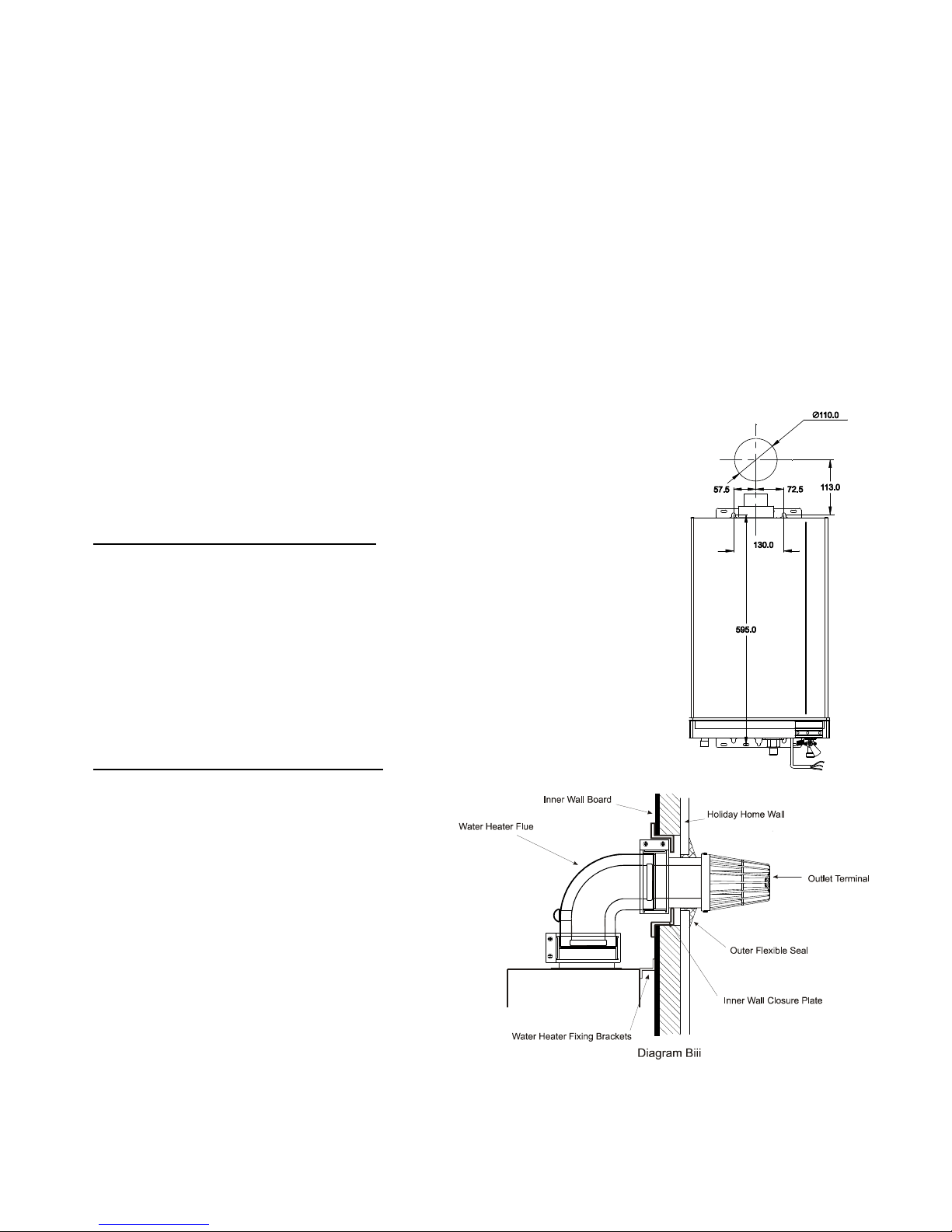
•200mm above the top of the heater case is required for the flue assembly.
•150mm is required below the heater to allow easy access to the gas isolation cock.
VENTILATION AND SERVICES REQUIREMENT
4. VENTILATION REQUIREMENTS
The following notes are for general guidance:
The Widney RSW10KL is a room sealed appliance and needs no purpose provided combustion air ventilation.
If the water heater is to be built into a small cupboard or compartment (i.e. at minimum clearances) and overheating
can be foreseen (i.e. close proximity to a cooking appliance etc.) permanent air vents are recommended for cooling
purposes in the cupboard or compartment.
5. ELECTRICITY SUPPLY
THIS APPLIANCE IS NOT DESIGNED TO BE USED WITH AN INVERTER, HOWEVER IF THERE IS NO OTHER
ALTERNATIVE THEN A PURE (TRUE) SINE WAVE INVERTER MUST BE USED.
•A 3 amp fused three pin plug and unswitched shuttered socket outlet (both complying with BS 1363 or
equivalent EN standard) or a 3 amp fused double pole isolator with a contact separation of 3mm in all poles
supplying only the heater should be used.
•Installation into a Bathroom – Please refer to the current IEE wiring regulations for installation and refer to the
data plate for product IP rating.
•THIS APPLIANCE MUST BE EARTHED
Where the product is fitted in a bathroom or an area that may be exposed to water spray please ensure that
appropriate electrical protection is provided to the mains connection.
6. GAS SUPPLY
The gas pipes must be copper. Do not connect plastic pipes directly to the heater. It is recommended that the copper
is extended to below the floor of the caravan/vehicle before connecting to plastic.
•Ensure the heater is set for the gas supply intended.
•A gas supply at the rating specified on the data label.
•Ensure the regulator is of sufficient capacity to carry the maximum water heater input plus the demand for any
other installed appliances.
•Ensure the connection between the supply/bottle and the caravan holiday home or park home is designed so
that no more than 2.4mbar of pressure drop occurs.
No more than 3 m of 15mm pipe should be used. Where the supply exceeds 3 m the pipe should be suitably
sized only reducing to 15mm before the water heater
•A full bore isolation valve must be fitted in the supply close to the water heater with either a union or
compression connection between the valve and the appliance to allow safe disconnection of the appliance.
•Connect the gas supply using a 15mm compression fitting.
•The complete installation must be tested for gas soundness.
7. CONNECTIONS TO WATER HEATER
The water pipes must be copper. Do not connect plastic pipes directly to the heater. It is recommended that the
copper is extended to below the floor of the caravan/vehicle before connecting to plastic.
•Ensure the water pipe complies with the requirements
•Remove any swarf or other residues in the pipes.
•Connect the heater using a 15mm compression tap connector fittings
•An isolation valve should be fitted to the inlet connection near to the appliance to allow service disconnection
of the appliance.
8. HOLIDAY HOME SERVICES
•Ensure that the pipe sizing and connections between the supply/bottle regulator and the caravan/vehicle is
designed so that no more than a maximum pressure drop of 2.5mbar occurs.
•This appliance must be fitted with an isolation valve not supplied.
•A cold water supply with a working pressure of a minimum of 0.18 bar measured at the cold water inlet to the
heater is required. Wherever possible the cold supply to the heater should be the first connection off the main
supply in order to minimise hot water flow reduction when cold water services are called for.

4
APPLIANCE DIMENSIONS:
A
C
D
B
E
F
G
I
J
M
N
O
P
K
LGAS
GAS
H
Q
MODEL
A
B
C
D
E
F
G
H
I
RSW10kl side flue
3
60
57
2
1
35
60
-
100
25
6
5
130
180
590
RSW10kl rear flue
3
60
57
2
1
65
60
-
100
25
95
130
180
590
J K L M N O P Q WEIGHT
40 35 55 175 90 125 187 168 13.6kg
70 65 85 175 90 125 187 168 13.6kg

5
Diagram Bi
INSTALLATION PROCEDURE
9. UNPACKING
The Water heater is supplied in a separate carton. Care should be taken when unpacking to ensure there is no
damage to the product.
Included in the Water heater carton are :- Installation and User instructions, Gas isolation valve & 100mm of 15mm dia
Copper tube.
In a separate pack: Flue kit – comprising of Inlet and outlet rigid tube – Terminal – Elbow - Clamping Rings (2) –
Sealing Collars (2).
THE WATER HEATER MUST BE INSTALLED WITH THE SUPPLIED FLUE KIT
10. SELECTING THE POSITION
Decide where the heater is to be fixed taking into account the installation requirements required under the relevant
standards and sections 1, 2,3,12 of these instructions.
11. WALL MOUNTING
The Water Heater can either be mounted with the flue system exiting to the rear or side of the appliance. For
Wall mounting with flue to the rear refer to paragraph entitled ‘Flue installation to the rear’.
Materials around the flue system – The outer flue will reach a maximum
temperature rise of 35
o
C. Care should be taken in ensuring that any materials
touching the outer flue are capable of withstanding this temperature for extended
periods. It is recommended that the rubber inner and outer seals are pushed into
the wall aperture before sealing. This will ensure that the outer flue pipe fits
centrally in the wall aperture.
Flue installation to the side: See diagram Bi
The water heater should be mounted on a suitable wall with sufficient structural strength
to ensure adequate support.
1. Mark the position of the fixing holes and the outlet aperture in the wall as
indicated in diagram Bi. Ensure that the position of the flue outlet meets with the
requirements of the relevant standards and is located as detailed in section 2.
2. Cut the hole for the flue liner through the wall of the home.
3. Fix the flue system to the water heater see section 12.
4. Fix the water heater securely through the fixing brackets located at the base
and top of the unit.
5. Go to section 12.
Flue installation to the rear: See diagram Biii
This method of installation requires a fixing kit part
no. RSWFIX01. The fixing kit comprises of two fixing
brackets to replace the fixing brackets fitted to the
water heater and a wall closure plate.
The water heater should be mounted on a suitable
wall with sufficient structural strength to ensure
adequate support.
1. Mark the position of the fixing holes and the
outlet aperture in the wall as indicated in
diagram Bi. Ensure that the position of the
flue outlet meets with the requirements of
the relevant standards and is located as
detailed in section 2.
2. Cut the hole for the flue liner through the
wall of the home.
3. Align the closure plate with the hole in the
inner wall and mark around the closure plate.
4. Cut out the inner section of the wall to fully recess the inner wall closure plate diagram Biii.
5. Insert the closure plate into the wall opening and fix with suitable fixings.
6. Fix the flue system to the water heater see section 12.
7. Go to section 12.

6
12. FLUE INSTALLATION
Positioning:
•The water heater MUST be installed so that the terminal is exposed to the external air.
•It is important that the position of the terminal allows free passage of air across it at all times.
•It is ESSENTIAL TO ENSURE, that products of combustion discharging from the terminal cannot re-enter the
building, or vehicle, through ventilators, windows, or other sources of natural air infiltration, such as other flues
etc, with the exception of doors, but not the opening windows thereof. The minimum acceptable dimensions
from the terminal to obstructions and ventilation openings must be as detailed in section 2.
Installing the flue system:
IMPORTANT
The standard horizontal flue kit supplied with the RSW10KL is part number RSWFK1M. This kit provides for 1
meter of flue length and one 90
0
elbow. Note: DO NOT INSTALL THIS APPLIANCE WITH MORE THAN ONE 90
0
Elbow (Bend) and more than 1.0 metre of flue length.
Never use a flue kit not specifically approved for use with this appliance.
NOTE: Where the home is pre-installed with the RSW10KL please consult the home manufacture for
replacement part numbers.
NOTE: The inner flue pipe of the terminal must be cut
accurately and must always be 100 mm longer than the outer
flue in order to ensure correct location in the terminal and
elbow. NOTE: The outer pipe has two holes at one end to
fix the terminal always cut the pipe at the opposite end to
these two holes.
To calculate the correct length of the outer flue use the
following formula and refer to diagram Ei
Formula: dimension X + Y + 20 mm (Note Dimension X is
the distance between the inner wall of the home and the
end of the elbow without the sealing collar attached; in
the case of rear flue installation the appliance should be
fitted with installation Kit RSWFIX01 if this kit is used
then the dimension X = 10mm.)
For calculating the inner flue lengths use the overall length of
the outer flue liner when cut to size and add 100mm.
Two sealing collars are provided to seal the external pipe
against the internal and external wall.RSWSC01.
The flue assembly must be installed with a slight downwards
incline of 2
0
towards the terminal to prevent the ingress of rain water, which may damage the heater. See diagram Eii.
Terminal Guard: if the position on the outlet terminal is less that 2 meters above ground level it is recommended that
a terminal guard be fitted.

7
Connecting the flue system:
Refer to diagram to assist in assembly.
1. Slide the inner flue pipe into the outer flue
pipe ensuring that the spacer on the inner flue
pipe is evenly positioned - Note for flue
lengths less than 300 mm the spacer is not
required, see diagram Eii.
2. Fit the clamping rings onto the elbow. Note:
ensure that the smaller diameter of the
clamping ring seal is facing the water
heater outlet spigot, see diagram Eiii.
3. Connect one end of the elbow to the water
heater and secure the clamping ring.
4. Slide the inner flue pipe into the elbow then slide
on the inner rubber collar over the flue pipe and
insert the outer flue pipe through the clamping
ring and into the elbow the secure the clamping
ring, see diagram Eiv.
Note: if fitting rear flue the inner rubber collar
should not be fitted.
Note; the inner flue pipe must protrude 55 mm
beyond the outer flue pipe, see diagram Eiv.
8. Fit the water heater to the wall by inserting the
flue pipe through the hole in the wall and
securing the water heater through the fixing
brackets into the pre drilled holes as detailed in section 11.
5. On the outside of the home slide the
outer collar over the outer flue pipe.
6. From the outside of the home locate the
terminal onto the inner flue pipe ensure
that the rubber seal is fitted to the
terminal before fixing to the flue pipe
then push the terminal over the outer
flue pipe.
NOTE The maximum gap on Fig Eiv
ensure that the inner flue pipe is
correctly aligned in the elbow on the
water heater before pushing on fully.
When the terminal is in the correct
position the holes in the terminal will align with the holes in the
outer flue pipe. Secure the terminal to the outer flue pipe with the
fixings provided.
7. If applicable slide the inner collar up to the inner wall and seal
with sealant. See diagram Evi
8. Slide the outer collar up to the outside wall and seal with sealant.
Outer and Inner sealing collars
Wall
Air Gap
Diagram Evi
Outer Flue
Note: 2°down

8
INSTALLATION COMPLETION
13. WIRING
Observe all the usual precautions to ensure that the electricity supply is isolated before beginning any installation
work. The heater should be wired as described in section 5.
Important: this appliance must be earthed.
14. GAS AND WATER CONNECTIONS
Connect the gas and water connections to the appliance using the appropriate fittings. Ensure that the pipe sizing,
material and connections comply with sections 6, 7, and 8 of this manual.
SETTING AND FIRST USE
15. THE CONTROL SCREEN
The control screen displays the water temperature, fan operation,
burner operation and water delivery and fault diagnostics information.
In normal operating conditions the screen will display the set water
temperature and operational mode, for example if the water heater is
not being used the temperature will be displayed together with a
shower head. If the water heater is working then the shower head will
display a water effect and the burner and fan will flash on and off.
The temperature of the water that will
be delivered from the appliance is set
by using the up and down buttons on
the left hand side of the panel.
To operate the water heater turn on the power from the mains – (the control panel will
light up and display the number 18 which confirms that PCB mode and settings are
correct for this appliance, the display will then go to a non-illuminated condition), then
switch on the water heater via the on—off switch on the control panel. The water heater
is now in operational mode and will automatically start up when the hot water tap is used.
Water temperature can be set between 35
0
C and 65
0
C it recommended that the optimal
temperature is 40
0
C
16. GENERAL GUIDANCE NOTES ON HOT WATER DELIVERY
The temperature of the hot water is governed by both the ambient temperature of
the cold water supply and its flow rate through the water heater. The flow rate of the
hot water is controlled by the hot outlet tap / shower.
Water Flow settings: The appliance is fitted with a manual water flow adjuster which
should be in the summer position for normal operation; however in very cold
conditions the water inlet temperature may be too low to heat the water effectively. If
this happens then the water flow switch should be set to the winter position.
The water heater can theoretically supply more than one outlet simultaneously;
however in practice the tap which is nearest will receive the most hot water. If the
shower is in use and a kitchen tap is opened virtually all the hot water will be
diverted to the kitchen as it offers the least resistance.
•Due to the restrictive nature of simple mixer showers it is wise to turn the temperature selector down on
the water heater before using the shower.
DO NOT PLACE YOUR HANDS under the tap or use the shower until this initial flow has passed.
Allow time (30 seconds) for the temperature to stabilise after making an adjustment at the tap before making further
adjustments.
17. APPLIANCE SAFETY LOCK-OUT
This water heater has a fault indicator built in to it on the front display, whenever a malfunction is detected in the water
heater the display panel will indicate a fault code and turn the water heater off. Please refer to the fault code section to
diagnose a fault.

9
COMMISSIONING ENGINEER AND END USER FAULT CODES
Fault
Code Problem Identified Action to take
E0 Input Water Temperature sensor
Fault
Switch off mains power supply – then restart by switching mains supply on and
pressing the on off button on the control panel – If problem persists contact
service
E1 Ignition Failure / No Flame Detected
Switch off mains power supply
Check gas supply and gas pressure at appliance
Restart by switching mains supply on and pressing the on off button on the
control panel
–
If problem persists contact service
E3 Blocked Flue—Abnormal wind
Condition
Switch off mains power supply
Check for blockage around outlet terminal
Leave for 30 minutes then restart by switching mains supply on and pressing
the on off button on the control panel – If problem persists contact service
E4 Fan or Power Fault
Switch off mains power supply –
Check mains supply and fuse
Restart by switching mains supply on and pressing the on off button on the
control panel – If problem persists contact service
E5 Outlet water temperature too high /
Over Temperature Protection
Switch off mains power supply –
Check flow of water supply to water heater
Switch on
Check temperature setting on water heater.
Turn to full and re test for temperature.
Turn Winter summer water valve to summer setting.
Switch off mains power supply
Restart by switching mains supply on and pressing the on off button on the
control panel – If problem persists contact service
E6 Water Outlet temperature sensor
failure
Check temperature setting on water heater.
Turn to full and re test for temperature.
Turn Winter summer water valve to winter setting.
Switch off mains power supply
Restart by switching mains supply on and pressing the on off button on the
control panel – If problem persists contact service
E7 DIP Switch incorrect setting
Factory Setting incorrect.
Switch off mains power supply
Switch of gas and water supply
Turn on all services
Restart water heater.
If problem persists contact service
F0 Power on start-up failure
Water is flowing through heater on power up.
Ensure water is NOT flowing through heater when power supplied.
Reset by turning off power and ensure all taps and shower are turned off. Re-
power water heater to clear fault code.

10
18. ROUTINE SERVICING
To ensure continued safe and efficient operation of the appliance it is recommended that it is checked and serviced at
regular intervals. The frequency of servicing will depend upon the particular installation conditions and usage but in
general once a year should be regarded as a minimum, even if only occasional usage has occurred. It is a legal
requirement that any service work MUST be carried out by a registered engineer.
Before leaving the factory the heater is pre-set in accordance with the information on the data plate. No adjustment is
necessary and under no circumstances should any of the seals be broken. This includes the removal of the front case
which can only be done by a qualified technician.
19. CLEANING
In addition to routine servicing carried out by a qualified technician it is recommended that the outer case be cleaned
periodically. This should be done with a soft dry cloth. Care should be taken not to damage the LCD control panel.
Periodically the flue terminal should be checked to ensure that it is clean and free of debris. A visual inspection is
recommended and if debris is noticed the appliance should be turned off and the terminal dismantled and cleaned. When
replacing the terminal ensure that it is correctly fitted – refer to section 12 of this manual.
20. SAFETY
It is essential that these instructions are strictly followed for the safe and economical operation of this appliance.
The appliance is a fan-assisted room sealed gas water heater and therefore the flue terminal MUST NOT BE
OBSTRUCTED under any circumstances. If it is damaged, turn off the appliance and consult your installer, or service
engineer. If it is known or suspected that a fault exists on the appliance it MUST NOT be used until the fault has been
rectified by a competent person.
21. PRECAUTIONS AGAINST FREEZING DURING WINTER STORAGE
During cold periods and if the water heater is situated in a place liable to freeze, the water must be completely drained
from the water heater as follows:
1. Turn off the cold water Supply.
2. Open all the hot water outlet taps on the installation.
3. Release the drain plugs fitted at the lowest point of the pipe work.
4. Open the bleed valve on the side of the water inlet fitting a few turns to allow air into the system.
NOTE: There is no drain plug fitted to the hot water heater side of the water heater.
When the operation is finished, close the hot water outlet taps and replace the drain plug and tighten the bleed valve on
the side of the water inlet fitting.
To put the water heater back into service, open the cold water supply.
NOTE: In a Caravan Holiday Home installation there may be a drain cock on the cold inlet under the van directly
below the water heater which may be used.
22. COMMISIONING
Before commissioning, ensure that the whole gas installation is purged and tested for soundness. Always ensure that
connections made to the appliance for gas type, gas pressure and water pressure are in accordance with the appliance
data plate.
23. POST INSTALLATION CHECKS
GAS CIRCUIT
Turn on the gas supply and check for leaks downstream of the isolation cock using leak detector spray.
WATER CIRCUIT
Turn on the water supply and check for leaks.
INITIAL OPERATION
Operate the heater as per the instructions in section 14 of this manual.
FINAL CHECKS
Re-light and test for gas soundness
Carry out an operating gas pressure test to ensure maximum potential performance.

11
USERS INSTRUCTIONS
Upon completion of testing the system the installer should:
•Give the instructions to the user and explain how the heater works.
•Demonstrate the operation of the heater.
•Explain the LOCKOUT and how to re-set.
•Stress the importance of an annual service by a registered engineer.
•Explain to the user how to proceed in case of freezing cold weather (drain down the water circuit, turn off the
gas and electrical supply).
•Explain the precautions to be taken to avoid frost damage
WARNINGS
THE OUTER CASE OF THIS PRODUCT IS FACTORY SEALED AND MUST NOT BE TAMPERED WITH BY A
NON COMPETENT PERSON. REMOVAL OF THIS SEAL WILL INVALIDATE THE WARRANTY.
PRECAUTIONS AGAINST FREEZING DURING WINTER STORAGE
DURING COLD PERIODS AND IF THE WATER HEATER IS SITUATED IN A PLACE LIABLE TO FREEZE, THE
WATER MUST BE COMPLETELY DRAINED FROM THE WATER HEATER AS FOLLOWS:
1. TURN OFF THE COLD WATER SUPPLY.
2. OPEN ALL THE HOT WATER OUTLET TAPS ON THE INSTALLATION.
3. RELEASE THE DRAIN PLUGS FITTED AT THE LOWEST POINT OF THE PIPE WORK.
4. OPEN THE BLEED VALVE ON THE SIDE OF THE WATER INLET FITTING A FEW TURNS TO ALLOW AIR
INTO THE SYSTEM.
NOTE: THERE IS NO DRAIN PLUG FITTED TO THE HOT WATER HEATER SIDE OF THE WATER HEATER.
WHEN THE OPERATION IS FINISHED, CLOSE THE HOT WATER OUTLET TAPS AND REPLACE THE DRAIN
PLUG.
TO PUT THE WATER HEATER BACK INTO SERVICE, OPEN THE COLD WATER SUPPLY.
NOTE: IN A CARAVAN HOLIDAY HOME INSTALLATION THERE MAY BE A DRAIN COCK ON THE COLD
INLET UNDER THE HOME DIRECTLY BELOW THE WATER HEATER WHICH MAY BE USED.
THE WATER AND GAS PIPES MUST BE COPPER. DO NOT CONNECT PLASTIC PIPES DIRECTLY TO THE
HEATER. IT IS RECOMMENDED THAT THE COPPER IS EXTENDED TO BELOW THE FLOOR OF THE
CARAVAN/VEHICLE BEFORE CONNECTING TO PLASTIC.
THE WATER HEATER MUST BE INSTALLED WITH THE SUPPLIED FLUE KIT
MATERIALS AROUND THE FLUE SYSTEM – THE OUTER WILL REACH A MAXIMUM TEMPERATURE RISE OF
35
O
C. CARE SHOULD BE TAKEN IN ENSURING THAT ANY MATERIALS TOUCHING THE OUTER FLUE ARE
CAPABLE OF WITHSTANDING THIS TEMPERATURE FOR EXTENDED PERIODS. IT IS RECOMMENDED THAT
THE RUBBER INNER AND OUTER SEALS ARE PUSHED INTO THE WALL APERTURE BEFORE SEALING. THIS
WILL ENSURE THAT THE OUTER FLUE PIPE FITS CENTRALLY IN THE WALL APERTURE.

12
Short Parts List
Short Parts List
Part Number
/ Description
Part Number / Description Part Number / Description
General Components
RSWBCU
Burner
Control Unit
RSWTF Transformer RSWTH01 Thermostat
RSWTHSET
Inlet and Outlet
Thermistor
RSWPS
Pressure switch RSWPRV01
Pressure relief valve
Flue System Components
RSWE Elbow RSWT Terminal RSWSC01 Sealing
Collar Flexible
Neoprene
RSWCR Clamping
Rings RSWCRUS
Clamping Ring
Upper Seal
Neoprene
RSWCRLS
Clamping Ring
Lower Seal
Neoprene
RSWTS
Terminal Seal
Neoprene
RSWFS Inner flue
seals ( x 2)
Neoprene
RSWFK1M Flue kit 1 Metre including
Terminal-Elbow Inner flue, Outer Flue,
Clamping Rings (2) – Sealing Collars (2).
RSWFIX01 Fixing Kit
RSWT01 Terminal Guard

13
Specification
Widney Leisure Ltd, Saxon Business Park, Stoke Prior, Bromsgrove, Worcestershire B60 4AD
Telephone +44(0) 1527577800 Fax +44(0)1527577900
Email: sales@widney-leisure.co.uk—web: www.widney-leisure.co.uk
W00542 – Issue R
Product Description Wall Mounted side flue, room sealed, fan assisted Water Heater with
electronic control for water temperature and safety operation
Model Name
RSW10KL
Specification
Value
Gas Type
37mbar – G31 Propane Only
Gas Category
I
3p
@30/37/50 mbar
Gas Burner Pressure
Internally Regulated to 19.0 mbar
Efficiency
Nominal Energy Consumption
Minimum Energy Consumption
20 kW
6.5 kW
Water Pressure
Max
Min
8.0 bar
0.18 bar
Min Water Flow
-
l/min
∆50
0
C
∆25
0
C
High Low
5.25 2.4
10.5 3.3
Supply Voltage
220~230V a.c. 50Hz
Power
60 W
Gas Consumption
High (20kW)
Low (6.5kW)
M
3
/hr Kg/hr
0.752 1.43
0.244 0.46
Appliance Type
C
13
Degree of Electrical Protection
IPX4D
Combustion Flue Gas Temperature
147
0
C

14
GB
RSW10KL
Chauffe-eau à gaz instantané
Adéquat pour une utilisation dans les pays suivants :
AT,BE,CH,DE,DK,ES,FI,FR,GB,GR,IE,IT,NL,PT,HU,PL,BG,CY,CZ,LT,RO,SI,SK
MANUEL D’INSTALLATION
RÉGLEMENTATIONS 1998 SUR LA SÉCURITÉ DU GAZ (INSTALLATION ET
UTILISATION) (TELLES QUE MODIFIÉES)
La loi exige que tous les appareils à gaz soient installés par un professionnel agréé,
conformément aux réglementations ci-dessus.
Le fait de ne pas installer correctement les appareils peut entraîner des poursuites
judiciaires. Il est de votre propre intérêt, et pour ce qui est de la sécurité, de vous assurer
de la conformité à la loi en vigueur.
Lisez attentivement ces instructions avant d’utiliser l’appareil. Observez tous les
avertissements applicables.
Ne touchez pas aux composants scellés et utilisez l’appareil conformément à ces
instructions.
RECOMMANDATIONS – POUR L’INSTALLATEUR
Cet appareil ne doit pas être installé, ajusté ou adapté à une utilisation avec un autre type de gaz.
RÉGLEMENTATIONS 1998 SUR LA SÉCURITÉ DU GAZ (INSTALLATION ET UTILISATION) (telles que modifiées)
La loi exige que tous les appareils à gaz soient installés par un professionnel agréé, conformément aux réglementations
ci-dessus.
Le fait de ne pas installer correctement les appareils peut entraîner des poursuites judiciaires.
Il est de votre propre intérêt, et pour ce qui est de la sécurité, de vous assurer de la conformité à la loi en vigueur.
En plus des réglementations ci-dessus, cet appareil doit être installé conformément aux réglementations de câblage IEE
actuelles, Document de santé et de sécurité No. 635 « Réglementations sur l’électricité sur le lieu de travail ». Cet
appareil doit également être conforme aux recommandations appropriées dans les éditions actuelles de toutes les
normes nationales concernées. Une attention toute particulière doit être portée sur les normes suivantes se rapportant à
une installation dans des véhicules habitables de loisir :
BS EN 1647:2004+A1:2008 Véhicules habitables de loisir ; mobil-homes ; exigences d’habitation concernant la santé et à
la sécurité.
BS EN 721:2004 Véhicules habitables de loisir : exigences de ventilation de sécurité.
BS EN 1949:2002 Spécification pour l’installation de systèmes GPL à des fins d’habitation dans des véhicules habitables
de loisir et dans d’autres véhicules.
BS 5440-1:2008 Évacuation et ventilation pour les appareils à gaz d’une puissance d’entrée nominale ne dépassant pas
70 kW net (gaz de 1
ère
, 2
ème
et 3
ème
famille). Spécification pour l’installation d’appareils à gaz à des cheminées et pour
l’entretien des cheminées.
BS5482-2:1977 Installations domestiques à gaz butane et propane : installations dans des caravanes et des habitations
non permanentes.
Codes de pratique
CoP 501
CoP 502
IMPORTANT : Les références aux normes ci-dessus sont uniquement présentées à titre indicatif. Les installateurs doivent
toujours vérifier pour veiller à ce que les références aux normes EN et BS de ce document soient conformes aux
dernières exigences.
L’installation doit être effectuée conformément aux réglementations nationales et locales et aux exigences de la Directive
sur les produits de construction.
Les instructions du fabricant Ne doivent PAS être considérées comme l’emportant sur les réglementations statutaires. Il
est nécessaire de toujours se reporter aux informations techniques fournies sur la plaque signalétique de l’appareil avant
d’installer cet appareil.
S’assurer que l’appareil est compatible aux réglementations locales.
F

15
INTRODUCTION
Le modèle WIDNEY RSW10KL est un chauffe-eau à gaz mural étanche, entièrement modulant, ventilé et commandé par
microprocesseur pour la distribution d’eau chaude domestique. Il convient tout particulièrement à une utilisation en
caravane ou mobil-home. Cet appareil n'est pas adapté pour les véhicules allant de la route
Robinet de purge
Régulateur de débit
d'eau été/hiver
Points de fixation
Câble secteur
RSW
10LK
Admission de gaz
Sortie d'évacuation
Panneau de commande
Admission d'eau froide
À FAIRE et À NE PAS FAIRE
LIRE les instructions d’installation avant d’installer le produit
VÉRIFIER que l’alimentation de gaz et d’eau correcte est disponible
UTILISER l’évacuation et le conduit d’évacuation recommandés
VÉRIFIER que le système d’évacuation est correctement installé avant la mise en service
N’installez PAS cet appareil à moins que vous soyez un installateur qualifié
N’utilisez PAS cet appareil avant que les contrôles d’installation aient été effectués
Conseils pour le POSITIONNEMENT et l’EMPLACEMENT du chauffe-eau
1. EMPLACEMENT DU CHAUFFE-EAU
Lors du positionnement du chauffe-eau, les limites suivantes DOIVENT être observées :
La position doit permettre une bonne évacuation.
Le chauffe-eau doit être installé sur un mur vertical droit capable de supporter son poids. Si le chauffe-eau est dans une
pièce renfermant une baignoire ou une douche, les commandes et l’alimentation électrique du chauffe-eau doivent être
situées de façon à ce que la personne utilisant la baignoire ou la douche ne puisse pas les atteindre. Une attention toute
particulière doit être portée sur les réglementations de câblage IEE actuelles et, en Écosse, sur les dispositions en
matière d’électricité des réglementations du bâtiment applicables en Écosse. Un compartiment utilisé pour renfermer
l’appareil DOIT être conçu et construit spécifiquement à cette fin. Un placard ou un compartiment existant peut être utilisé,
à condition qu’il soit modifié en conséquence.

16
Veuillez lire les avertissements figurant à la fin des ces instructions avant d’entreprendre l’INSTALLATION.
2. POSITION DE L’ÉVACUATION
Le chauffe-eau doit être installé de façon à ce que l’évacuation soit exposée à l’air extérieur.
Il est important que la position de l’évacuation permette à tout moment le libre passage de l’air à travers.
Il est essentiel de s’assurer que les produits de la combustion se déchargeant à travers l’évacuation ne puissent pas
pénétrer de nouveau le bâtiment ou le véhicule, à travers les ventilateurs, les fenêtres ou d’autres sources d’infiltration
d’air naturelle, comme d’autres évacuations, etc., à l’exception des portes, mais pas des fenêtres ouvrantes de
l’habitation.
Les dimensions minimales acceptables de l’évacuation aux obstructions et aux ouvertures de ventilation sont les
suivantes :
Directement en dessous d’un évent fixe ouvrant ou d’une fenêtre, etc................ 300mm
Adjacente à un évent fixe ouvrant ou une fenêtre, etc.……………..................... 300mm
Sous les gouttières........................................................................................... 75mm
À partir d’un tuyau d’évacuation vertical……....................................................... 75mm
À partir d’un angle intérieur ou extérieur………………........................................ 300mm
Si une évacuation est installée dans une position où des enfants, des personnes âgées ou des personnes
handicapées y ont accès (moins de 1,5 m au-dessus de marches, d’un plancher ou du sol), un dispositif de
protection adéquat doit être installé. Dans certaines conditions météorologiques, l’évacuation dégage un panache
de vapeur.
•NE PAS INSTALLER à moins de 300 mm à la verticale d’une évacuation sur la même paroi ou à l’horizontale à
partir d’une évacuation sur la même paroi.
3. DÉGAGEMENTS MINIMUMS
•Il est nécessaire d’observer des dégagements minimums de 5 mm à l’avant et sur les côtés du chauffe-eau.
Toutefois, un accès total à l’avant sous la forme d’une porte ouvrante doit être assuré pour pouvoir accéder aux
commandes et accomplir les tâches d’entretien.
•Un dégagement de 200 mm au-dessus du haut du carter du chauffe-eau est nécessaire pour l’ensemble
d’évacuation.
•Un dégagement de 150 mm est exigé sous le chauffe-eau pour faciliter l’accès au robinet d’isolement du gaz.
•EXIGENCES DE VENTILATION ET DE BRANCHEMENTS
4. EXIGENCES DE VENTILATION
Les remarques suivantes sont présentées à titre indicatif :
Le Widney RSW10KL est un appareil étanche et ne nécessite aucune ventilation d’air de combustion spécifique.
Si le chauffe-eau est intégré à un petit placard ou compartiment (c.-à-d. avec des dégagements minimum) et qu’une
surchauffe est observée (c.-à-d. à proximité rapprochée d’un appareil de cuisson, etc.), des évents d’air permanents sont
recommandés à des fins de refroidissement dans le placard ou le compartiment.
5. ALIMENTATION ÉLECTRIQUE
CET APPAREIL N’EST PAS CONÇU POUR ETRE UTILISE AVEC UN CONVERTISSEUR, CEPENDANT S’IL N’Y A PAS
D’AUTRE ALTERNATIVE, ALORS UN VRAI CONVERTISSEUR DOIT ETRE UTILISE.
•Une fiche à trois broches à fusible de 3 ampères et une prise non commutable à éclipse de protection (toutes
deux conformes à la BS 1363 ou une norme EN équivalente) ou un sectionneur bipolaire à fusible de 3 ampères
avec une séparation de contact de 3 mm pour tous les pôles alimentant uniquement le chauffe-eau doivent être
utilisés.
•Installation dans une salle de bains – Veuillez vous reporter aux réglementations de câblage IEE actuelles pour
l’installation et à la plaque signalétique pour le degré de protection IP du produit.
•CET APPAREIL DOIT ÊTRE RELIÉ À LA TERRE
Lorsque le produit est installé dans une salle de bains ou dans un endroit susceptible d’être exposé à des projections
d’eau, veuillez vous assurer que le raccordement au secteur est équipé d’une protection électrique appropriée.
6. ALIMENTATION DE GAZ
Les conduites de gaz doivent être en cuivre. Ne branchez pas de tuyaux en plastique directement au chauffe-eau. Il est
recommandé que les conduites en cuivre se prolongent jusque sous le plancher de la caravane/du véhicule avant de
brancher des éléments en plastique.

17
•S’assurer que le chauffe-eau est réglé pour l’alimentation de gaz prévue.
•Une alimentation de gaz aux spécifications figurant sur la plaque signalétique.
•S’assurer que le régulateur est d’une capacité suffisante pour accepter la puissance maximum du chauffe-eau,
ainsi que la demande de tout autre appareil installé.
•S’assurer que le raccord entre l’alimentation/la bouteille et que la caravane ou le mobil-home est conçu de
manière à éviter toute chute de pression supérieure à 2,4 mbar.
Il ne faut pas utiliser plus de 3 mètres de conduit de 15 mm. Lorsque la longueur d’alimentation dépasse 3 m, le conduit
doit être de taille correcte, avant de le réduire à 15 mm avant le chauffe-eau.
•L’alimentation doit être équipée d’un clapet d’isolement à passage intégral près du chauffe-eau avec soit un
raccord union soit un raccord de compression entre le clapet et l’appareil pour permettre le débranchement en
toute sécurité de l’appareil.
•Raccordez l’alimentation de gaz en utilisant un raccord de compression de 15 mm.
•L’installation complète doit être testée pour la sûreté du gaz.
7. RACCORDS AU CHAUFFE-EAU
Les conduites d’eau doivent être en cuivre. Ne branchez pas de tuyaux en plastique directement au chauffe-eau. Il est
recommandé que les conduites en cuivre se prolongent jusque sous le plancher de la caravane/du véhicule avant de
brancher des éléments en plastique.
•S’assurer que la conduite d’eau est conforme aux exigences
•Retirez tout copeau ou tout débris de la conduite.
•Raccordez le chauffe-eau en utilisant des raccords de connecteur à comprimer de 15 mm
•Un clapet d’isolement doit être installé sur le raccord d’admission près de l’appareil pour permettre le
débranchement de l’appareil à des fins d’entretien.
8. BRANCHEMENTS DE RÉSIDENCE SECONDAIRE
•S’assurer que la dimension des tuyaux et les raccords entre l’alimentation/le régulateur de bouteille et la
caravane/le véhicule sont conçus de manière à éviter toute chute de pression supérieure à 2,5 mbar.
•Cet appareil doit être équipé d’un clapet d’isolement (qui n’est pas fourni).
•Une alimentation d’eau froide d’une pression de service d’un minimum de 0,18 bar mesurée au niveau de
l’admission d’eau froide du chauffe-eau est exigée. Si possible, l’alimentation d’eau froide du chauffe-eau doit être
le premier raccord à partir de l’alimentation principale afin de minimiser la réduction de débit d’eau chaude lors
des demandes en eau froide du système.

18
DIMENSIONS DE L’APPAREIL :
A
C
D
B
E
F
G
I
J
M
N
O
P
K
LGAZ
GAZ
H
Q
MODÈL
E
A
B
C
D
E
F
G
H
I
RSW10kl
évacuation
latérale
360 572 135 60-100 25 65 130 180 590
RSW10kl
évacuation
arrière 360 572 165 60-100 25 95 130 180 590
J K L M N O P Q POIDS
40 35 55 175 90 125 187 168 13,6 kg
70 65 85 175 90 125 187 168 13,6 kg

19
PROCÉDURE D’INSTALLATION
9. DÉBALLAGE
Le chauffe-eau est fourni dans un carton séparé. Veuillez déballer avec soin afin d’éviter tout endommagement du
produit.
Le carton d’emballage du chauffe-eau comprend :- Les instructions d’installation et d’utilisation
Séparé : Le kit d’évacuation – incluant un tube rigide d’admission et de sortie – le conduit – un raccord coudé – des
bagues de fixations (2) – des manchons d’étanchéité (2).
LE CHAUFFE-EAU DOIT ÊTRE INSTALLÉ AVEC LE KIT D’ÉVACUATION.
10. SÉLECTION DE LA POSITION
Choisissez l’endroit où le chauffe-eau doit être installé en tenant compte des exigences d’installation conformément aux
normes appropriées et aux sections 1, 2, 3 et 12 de ces instructions.
11. FIXATION MURALE
Le chauffe-eau peut être installé avec le système d’évacuation sortant sur l’arrière ou sur le côté de l’appareil.
Pour la fixation murale avec l’évacuation à l’arrière, voir le paragraphe intitulé « Installation de l’évacuation à
l’arrière ».
Matériaux autour du système d’évacuation – L’évacuation externe va atteindre une
température maximum de 35°C. Il est donc nécessaire de s’assurer que les
matériaux touchant l’évacuation externe sont capables de résister à cette
température pendant des périodes prolongées. Il est recommandé que les
garnitures d’étanchéité internes et externes soient poussées dans l’ouverture
murale avant de recouvrir le tout. Ceci permettra de s’assurer que le conduit
d’évacuation externe se loge bien au centre de l’ouverture murale.
Installation de l’évacuation sur le côté : voir Schéma Bi
Le chauffe-eau doit être installé sur une paroi adéquate d’une résistance structurelle
suffisante à assurer un support adéquat.
1. Marquez la position des trous de fixation et l’ouverture de sortie dans le mur
comme il est indiqué sur le Schéma Bi. Assurez-vous que la position de la
sortie d’évacuation est conforme aux exigences des normes appropriées et aux
détails figurant en section 2.
2. Découpez le trou pour la garniture de l’évacuation à travers le mur de
l’habitation.
3. Fixez le système d’évacuation au chauffe-eau. Voir section 12.
4. Fixez le chauffe-eau en toute sécurité à l’aide des supports de fixation situés à
la base et en haut de l’unité.
5. Passez à la section 12.
Installation de l’évacuation sur l’arrière : voir Schéma Biii
Cette méthode d’installation réclame l’utilisation d’un kit
de fixation No. RSWFIX01. Le kit de fixation comprend
deux supports de fixation montés sur le chauffe-eau et
d’une plaque d’obturation murale.
Le chauffe-eau doit être fixé sur un mur adéquat d’une
résistance structurelle suffisante à assurer un support
adéquat.
1. Marquez la position des trous de fixation et
l’ouverture de sortie dans le mur comme il est
indiqué sur le Schéma Biii. Assurez-vous que la
position de la sortie d’évacuation est conforme
aux exigences des normes appropriées et aux
détails figurant en section 2.
2. Découpez le trou pour la garniture de
l’évacuation à travers le mur de l’habitation.
Paroi de l'habitation secondaire
Garniture d'étanchéité flexible externe
Plaque d'obturation murale interne
Évacuation du chauffe-eau
Terminal de sortie
Panneau mural interne
Schéma
Bi

20
3. Alignez la plaque d’obturation murale avec le trou dans la paroi interne et marquez le pourtour de la plaque
d’obturation.
4. Découpez la section interne de la paroi pour accepter entièrement la plaque d’obturation de paroi interne, voir
Schéma Biii.
5. Insérez la plaque d’obturation dans l’ouverture murale et assujettissez-la à l’aide de fixations adéquates.
6. Fixez le système d’évacuation au chauffe-eau, voir section 12.
7. Passez à la section 12.
12. INSTALLATION DE L’ÉVACUATION
Positionnement :
•Le chauffe-eau DOIT être installé de façon à ce que l’évacuation soit exposée à l’air extérieur.
•Il est important que la position de l’évacuation permette à tout moment le libre passage de l’air à travers.
•Il est ESSENTIEL DE S’ASSURER que les produits de la combustion se déchargeant à travers l’évacuation ne
puissent pas pénétrer de nouveau le bâtiment ou le véhicule, à travers les ventilateurs, les fenêtres ou d’autres
sources d’infiltration d’air naturelle, comme d’autres évacuations, etc., à l’exception des portes, mais pas des
fenêtres ouvrantes de l’habitation.
•Les dimensions minimales acceptables de l’évacuation aux obstructions et aux ouvertures de ventilation doivent
être conformes à celles détaillées en section 2.
Installation du système d’évacuation :
IMPORTANT
Le kit d’évacuation horizontale standard fourni avec l’appareil RSW10KL porte le numéro de pièce RSWFK1M. Ce
kit fournit 1 mètre de longueur d’évacuation et un coude à 90°. Remarque : NE PAS INSTALLER CET APPAREIL
AVEC UN COUDE DE PLUS DE 90°et une longueur d’évacuation supérieure à 1,0 mètre.
Ne jamais utiliser un kit d’évacuation qui n’est pas spécifiquement agréé pour cet appareil.
REMARQUE : Lorsque l’habitation est déjà équipée d’un RSW10KL, veuillez consulter le fabricant de l’habitation
pour obtenir les numéros des pièces de rechange.
REMARQUE : Le conduit d’évacuation interne du terminal
doit être découpé avec précision et doit toujours être de 100
mm plus long que le conduit d’évacuation externe afin
d’assurer l’emplacement correct du terminal et du raccord
coudé. REMARQUE : Le conduit externe est muni de deux
trous à une extrémité pour fixer le terminal. Toujours
couper le conduit à l’extrémité opposée à ces deux trous.
Pour calculer la longueur correcte de l’évacuation externe,
utilisez la formule suivante et reportez-vous au Schéma Ei.
Formule : dimension X + Y + 20 mm (à noter que la
dimension X est la distance entre la paroi interne de
l’habitation et l’extrémité du coude sans la garniture
d’étanchéité fixée ; dans le cas d’une installation
d’évacuation arrière, l’appareil doit être fixé à l’aide du kit
d’installation RSWFIX01 ; si ce kit est utilisé, alors la
dimension X = 10 mm.)
Pour calculer les longueurs d’évacuation internes, utilisez la
longueur hors-tout de la garniture d’évacuation interne
lorsqu’elle est découpée aux dimensions et ajoutez 100mm.
Deux manchons d’étanchéité sont fournis pour sceller le
conduit externe contre la paroi interne et externe. RSWSC01.
L’ensemble d’évacuation doit être installé avec une légère inclinaison de 2°vers le terminal pour éviter la pénétration de
l’eau de pluie qui risque d’endommager le chauffe-eau. Voir le Schéma Eii.
Protection du terminal : si la position sur le terminal de sortie est inférieure à 2 mètres au-dessus du niveau du sol, il est
recommandé d’installer une protection.
Schéma Ei
Chauffe-eau
Coude sans fixation
Paroi interne
Paroi externe
Longueur de conduit d'évacuation max.,
y compris le terminal = 1 mètre
Other manuals for RSW10KL
2
Table of contents
Languages:
Other Widney Heater manuals