Wieland Wipos UPS 20-960 User manual

wipos UPS 20-960
Uninterruptable Power Supply
USER MANUAL
Doc.-No. BA001052
Updated: 11/2018 (Rev. A)

Copyright
Wieland Electric GmbH | BA001052 (Rev. A) | 11/2018 2
COPYRIGHT
This document is copyright-protected. The rights derived from this cop-
yright are reserved for Wieland Electric GmbH. Reproduction of this doc-
ument or parts of this document is only permissible within the limits of
the statutory provision of the Copyright Act. Any modification or abridg-
ment of the document is prohibited without the express written agree-
ment of Wieland Electric GmbH.
Any other product or trade names listed in these operating instructions
are the trademarks or registered trademarks of the respective owners.
NOTE
Every effort has been made to ensure that the information contained in
this document was complete and accurate at the time of publishing.
Nevertheless, the authors retain the right to modify the information. This
customer document describes all the hardware units and functions
known at the present time. Descripti
ons may be included for units which
are not present at the customer site. The exact scope of delivery is de-
scribed in the respective purchase contract.
Conformity
Information
For more information regarding CE marking and Declaration of Conform-
ity
(DoC), please contact your local Wieland Electric customer service
organization.
Technical support
Up-to-date information concerning the product is available from the following
websites:
http://www.wieland-electric.com/
http://eshop.wieland-electric.com/
Technical support
Industrial Automation -Electronics
Hotline:
+49 951 / 93 24-995
E-Mail:
AT.TS@wieland-electric.com
Address
Wieland Electric GmbH
Brennerstraße 10-14
96052 Bamberg
Phone: +49 (0) 9 51 93 24-0
Fax: +49 (0) 9 51 93 24-198
E-mail: info@wieland-electric.com
http://eshop.wieland-electric.com
http://www.wieland-electric.com

Contents
Wieland Electric GmbH | BA001052 (Rev. A) | 11/2018 3
Table of Contents
1About this manual ............................................................................................................................... 5
1.1 Target groups and qualification of personnel ............................................................................. 5
1.2 Structure of the manual .............................................................................................................. 5
1.3 Presentation of safety-relevant information ................................................................................ 5
2Product disposal instructions .............................................................................................................. 7
3Product description ............................................................................................................................. 8
3.1 Overview of the UPS module's front........................................................................................... 8
4Features and benefits ........................................................................................................................ 10
5Function description .......................................................................................................................... 11
5.1 UPS mode ................................................................................................................................. 12
5.1.1 Backup (battery mode) .......................................................................................................... 12
5.1.2 Battery health monitor ........................................................................................................... 12
5.1.3 Battery charger ...................................................................................................................... 13
5.1.4 Coulomb counter ................................................................................................................... 15
5.1.5 PC shutdown and automatic restart ...................................................................................... 15
5.1.6 Cold start ............................................................................................................................... 16
5.1.7 Blink output on backup ......................................................................................................... 17
5.2 DC-DC mode ............................................................................................................................. 17
5.3 Current limit .............................................................................................................................. 18
5.3.1 Current limit in UPS mode ..................................................................................................... 18
5.3.2 Current limit in DC-DC mode ................................................................................................ 18
5.4 Inhibit ........................................................................................................................................ 18
5.5 Modbus ..................................................................................................................................... 19
6User interface .................................................................................................................................... 23
6.1 Status ........................................................................................................................................ 24
6.2 Settings ..................................................................................................................................... 24
6.3 Info menu .................................................................................................................................. 33
6.4 Logs ........................................................................................................................................... 34
6.4.1 Info ........................................................................................................................................ 34
6.4.2 Alarms ................................................................................................................................... 36
6.4.3 Events .................................................................................................................................... 40
6.5 Wizard (system configuration) .................................................................................................. 40

Contents
Wieland Electric GmbH | BA001052 (Rev. A) | 11/2018 4
Table of Figures
Figure 1 Front panel view ........................................................................................................................... 8
Figure 2 Terminal block 1 ........................................................................................................................... 8
Figure 3 Terminal block 2 ........................................................................................................................... 9
Figure 4 Simplified block diagram for UPS 20-960 .................................................................................. 11
Figure 5 UPS connection example ........................................................................................................... 12
Figure 6 Internal resistance measurement ............................................................................................... 13
Figure 7 Lead acid and Lithium charging algorithm ................................................................................. 14
Figure 8 Nickel charging algorithm .......................................................................................................... 14
Figure 9 Figure 7: Supercapacitors charging algorithm ........................................................................... 14
Figure 10 Shutdown and restart chart ..................................................................................................... 15
Figure 11 DC-DC connection example ..................................................................................................... 17
Figure 12 UPS status screen .................................................................................................................... 24
Figure 13 DC-DC status screen ................................................................................................................ 24
Figure 14 Alarm screen ............................................................................................................................ 24
Figure 15 Log Screen ............................................................................................................................... 34
1|About this manual
Wieland Electric GmbH | BA001052 (Rev. A) | 11/2018 5
1About this manual
Please read this section carefully before you use this manual and the
wipos
UPS from Wieland. Here you
will find all the information required for commissioning and operation.
1.1 Target groups and qualification of personnel
Commissioning and installation of components for such types of installations must be considered.
Therefore, the system manual is targeted at the following:
•Those who can verify that they have the corresponding training and already have corresponding
basic knowledge
•System integrators
•Electricians
1.2 Structure of the manual
As a guidance the overall table of contents is available in the manual at the beginning.
1.3 Presentation of safety-relevant information
Information that warns of personal injury or property damage are emphasized by safety instructions.
Please read this information carefully.
This operating manual uses various safety notices that are assigned according to the severity of a potential
hazard:
Danger!
Immediate or likely danger. Personal injury or death is possible.
Warning!
Possible danger. Not heeding this warning can lead to minor injuries.
Attention!
Damages to property is likely if these warnings are not heeded.
NOTE:
Supplementary information and useful tips, indirectly related to the safety of personnel or property.
"Danger" or "Warning" are strictly used for cases which present a risk to life or limb. Damage to property
only falls into these categories if there is also a risk of personal injury that corresponds to these levels.
DANGER
WARNING
ATTENTION
NOTE

1|About this manual
Wieland Electric GmbH | BA001052 (Rev. A) | 11/2018 6
Please, observe the following instructions:
NOTE:
Personnel which installs, programs, operates or maintains this device must have read and understood these in-
structions.
Warning!
The personnel must be thoroughly familiar with all warnings, notes and procedures described in these operating
instructions.
Where necessary, safety precautions and safety devices must comply with the applicable regulations.
Damaged products must neither be installed nor put into operation. In case of a defect, please return the device to
Wieland Electric.
The unit must not be opened.
Do not insert any objects into the unit!
Keep the unit away from fire and water
Attention!
Ensure appropriate installation before start of operation.
Do not cover any air ventilation holes.
Use the device only as intended.
NOTE
WARNING
ATTENTION

2|Product disposal instructions
Wieland Electric GmbH | BA001052 (Rev. A) | 11/2018 7
2Product disposal instructions
The WEEE (Waste Electrical and Electronic Equipment) directive has been introduced to ensure that elec-
trical/electronic products are recycled using the best available recovery techniques to minimize the impact
on the environment.
This product contains high quality materials and components which can be recycled. At the end of its life
this product MUST NOT be mixed with other commercial waste for disposal. Check the terms and con-
ditions of your supplier for disposal information.

3|Product description
Wieland Electric GmbH | BA001052 (Rev. A) | 11/2018 8
3Product description
NOTE:
Use latest device Documentation, Software and Firmware to ensure reliable operation of the system (down-
loadable from www.wieland-electric.com).
The UPS 20-960 is a microprocessor controlled unit that can perform two functions:
•UPS rated 960 W / 20 A usable in any system rated 12 … 48 V DC
•DC-DC converter (non-isolated) rated 960 W / 20 A usable in any combination of IN/OUT voltages
12 … 48 V DC
For the UPS function, it may use a battery of 12 V, independently of the operating load voltage. For any
supply voltages (12 … 48 V DC) it may use also multiple battery configuration (10 … 58 V DC). The UPS
module monitors the voltage coming from a DC power supply and in case of power failure a backup
battery is supplying the energy to the load. In normal condition the battery is kept charged by an inte-
grated battery charger supporting various battery chemistries.
As a DC-DC converter (no battery present) the input must be connected to the battery connector. The
input voltage is converted to any output voltage as per the set-up.
3.1 Overview of the UPS module's front
NOTE
1. Alarm LED indicator: ON when the unit is in
backup. Blinks at 1 Hz rate in case of error.
2. Modbus over USB: Used to connect a PC with
user software or custom application for remote
monitoring and controlling. Firmware update is
also possible through USB connection.
3. Temperature sensor: Optional temperature sen-
sor (
wipos
UPS 20 Sensor) to measure the battery
temperature for protection and temperature com-
pensated charge method.
4. Terminal block 1
5. Terminal block 2
6. Display area: provides information regarding the
device status.
7. Control keys: 4 push buttons are provided to navi-
gate through the menus and to select the various
functions.
8. Relays dry contacts: 2 relays (signal contacts) are
present for remote monitoring. See no. 26 in sec-
tion 6.2 for more details.
9. Modbus over RS485: Used to connect a PC with
user software or custom application for remote
monitoring and controlling. Firmware update is
also possible through RS485 connection.
10. Inhibit input: A voltage between 5 V DC and
30 V DC applied to this input activates the inhibit
function. See section 5.4 for more details.
1
3
2
4
5
6
7
Figure
1 Front panel view
8
9
10
11
Figure
2
Terminal block 1

3|Product description
Wieland Electric GmbH | BA001052 (Rev. A) | 11/2018 9
11. Auxiliary output supply: Maximum 5 A supply
from the battery (unregulated).
12. Input connection: 2 connectors are provided for
input connection. This must be connected to a
power supply rated 12 … 48 V DC.
13. Output connection: 2 connectors are provided for
output connection. It must be connected to the
load to be backed up.
14. Battery / DC-DC input connection: 2 connectors
are provided for battery connection. This must be
connected to the battery in UPS mode or to the
power supply in DC-DC mode. Although the unit is
protected the correct polarity must be respected
12
13
14
Figure
3 Terminal block 2

4|Features and benefits
Wieland Electric GmbH | BA001052 (Rev. A) | 11/2018 10
4Features and benefits
The main features are:
•Integrated battery charger for 12 … 48 V DC multi-chemistries batteries with a charging current
up to 20 A
•Can be operated with SUPERCAP capacitors instead of batteries
•20 A or 960 W rated load
•Automatic sensing of input voltage, load current and battery current
•Battery protection against reverse polarity connection and overcurrent
•Battery health monitoring system: measuring battery resistance, battery temperature, charge/dis-
charge cycles and Coulomb counter
•User settable maximum backup time
•Remote inhibit input
•Connection for a battery thermal sensor (optional)
•Modbus over USB and RS485 interfaces for control and monitoring
•Auxiliary output from the battery voltage (max. 5 A), protected against overcurrent/short circuit
•Suitable for energy management applications
•Suitable for user software
Embedded user interface:
•4 keys and 1 color graphic LCD display
•Allows online device configuration
•Displays the UPS module's status, logs and alarms
•2 dry contacts for programmable status signals
PC user software used for:
•Connection through Modbus
•Remote monitoring and configuration
•Firmware upgrade
•Same functionalities of the embedded user interface with the ease of the PC benefits

5|Function description
Wieland Electric GmbH | BA001052 (Rev. A) | 11/2018 11
5Function description
The UPS 20-960 is a high performance digitally controller DC-UPS that can be used in any DC system
with a rated voltage between 12 V and 48 V and up to 20 A.
At the core of the device a bidirectional DC/DC buck-boost converter (see Figure 4) acts as a battery
charger when the input supply is present. In case of a power outage (backup) the converter keeps the
output voltage regulated draining power from the battery. The converter is digitally controlled.
Figure 4 Simplified block diagram for UPS 20-960
Input
Input
switch
I
U
Input voltage
and current
measurement
I
U
Output voltage
and current
measurement
Output
I
U
Battery voltage
and current
measurement
I
U
Auxiliary voltage
and current
measurement
Auxiliary
supply
Battery
30A
Fu se
DC
DC
Bidirectional
digital control
DC/DC
converter
Battery
reverse
polarity
protection
Digital
fuse
uController
Power path
Monitoring and control
Battery health
monitor Modbus/RTU
USB
RS485
I/O
2xRelays
Inhibit
HMI
5|Function description
Wieland Electric GmbH | BA001052 (Rev. A) | 11/2018 12
5.1 UPS mode
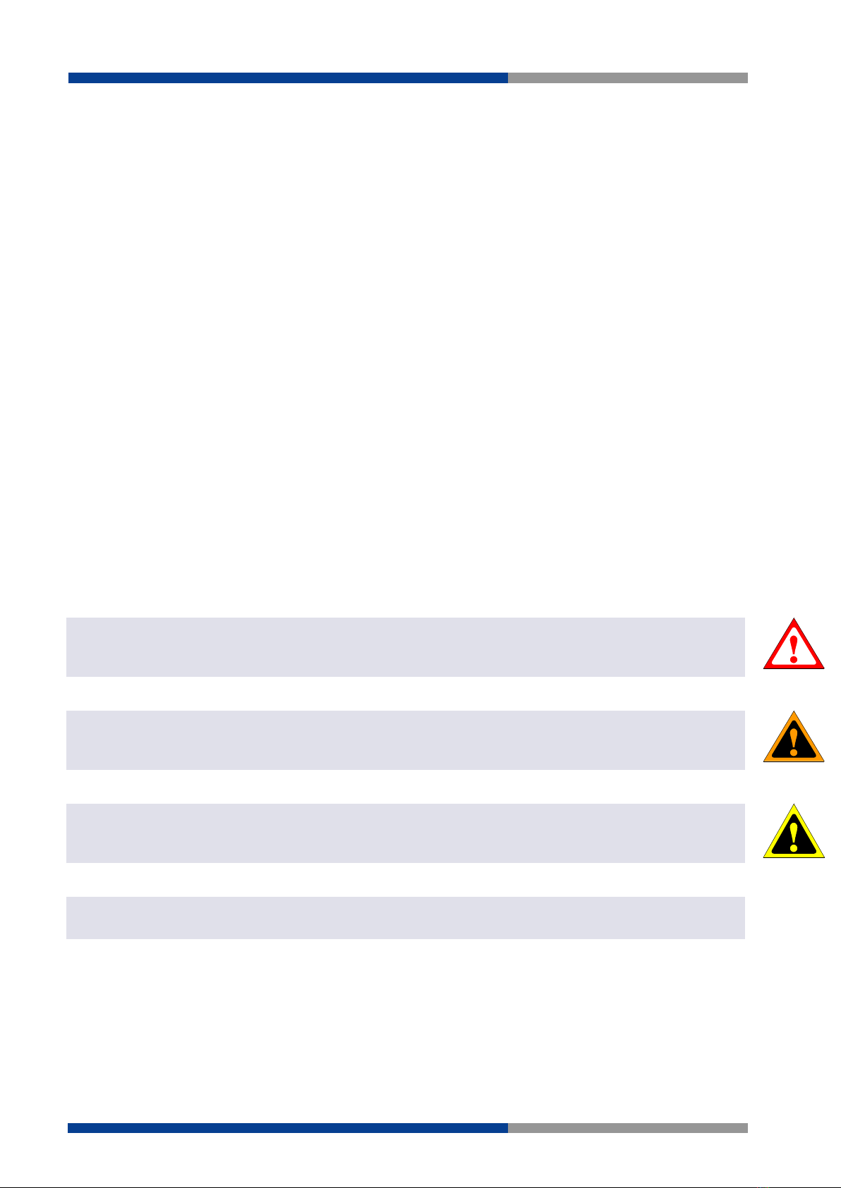
Figure 5 UPS connection example
In UPS mode the UPS module protects a load from unwanted power interruption in case of mains failure.
An example of UPS connection is given in Figure 5.
When the input is present, the UPS module acts as a bypass, connecting the input to the output via the
input switch. Meanwhile, if required, the battery is charged. During bypass there is no voltage conversion,
therefore the output supply voltage is equal to the input voltage.
In case of power outage, the UPS module takes energy from the battery to keep the output regulated at
nominal output voltage. See no. 20 in section 6.2 for more details.
5.1.1 Backup (battery mode)
The system is in backup mode if the supply for the output is sourced from the battery (input supply
missing). During backup the battery is monitored continuously to prevent over discharge.
A programmable backup timer is also implemented in order to fix a maximum backup time during
power outages. This allows preserving the battery life and shortening the recharge time, avoiding dis-
charging the battery when not needed. See no. 24 in section 6.2 for more details.
During backup the internal Coulomb counter is used to give an estimation of the residual charge of the
battery.
Backup starts when the output voltage is lower than 90% of the nominal output voltage. See no. 20 in
section 6.2 for more details.
5.1.2 Battery health monitor
The battery health monitor is composed of:
•Internal resistance measurement: The resistance is periodically measured. The internal resistance
is a good indicator of the battery health status; a sudden increase of the internal resistance indi-
cates a potential problem on the battery or on the battery wiring.
•Temperature measurement: The battery temperature is monitored through an optional tempera-
ture sensor (
wipos
UPS 20 Sensor). The battery charger takes into account the battery tempera-
ture and provides a temperature compensated charging voltage. In case of over or under temper-
ature the system disconnects the battery to prevent damage.
•Coulomb counter: Estimates the remaining battery capacity and consequently the available
backup time.
•Deep discharge protection: It protects against the deep discharge of the battery which can lead
to its irreversible damage.

5|Function description
Wieland Electric GmbH | BA001052 (Rev. A) | 11/2018 13
The battery internal resistance (Ri) is measured by draining a defined AC current through an active load
(AL) from the battery and measuring the AC voltage drop across the load terminals. The principle is rep-
resented in Figure 6.
Figure 6 Internal resistance measurement
The measured resistance is the sum of the
battery internal resistance
, the
cables resistance
and the
con-
nectors resistance
, therefore cabling problem such as loose connectors are also detected with Ri meas-
urement.
When high capacity batteries and/or small and long cables are used, Rcables+Rcon may be > Ri.
5.1.3 Battery charger
The battery charger supports batteries such as Lead-Acid, Nickel, Lithium and Supercapacitors. The
charging algorithm for each chemistry is given below.
The battery charger automatically reduces the current to avoid exceeding the maximum input current in
case of high current load. See no. 21 in section 6.2 for more details.
The user must set the following parameters to allow the charger to perform correctly:
•Battery type (see no. 5 in section 6.2)
•Battery charge voltage (see no. 6 in section 6.2)
•Battery charge current (see no. 7 in section 6.2)
•Battery float voltage (see no. 8 in section 6.2)
The battery charge terminates in case at least one of the following conditions are satisfied:
•Low current: The measured battery charge current is lower than 10% of the battery charge cur-
rent while the measured voltage is at least 98% of the battery charge voltage.
•Timer: the charge is terminated after the battery has been charged for a predetermined amount
of time. The value is automatically calculated by the device.
For Nickel batteries only, the following conditions are also checked:
•Temperature Cutoff (TCO): The battery temperature if higher than the "Battery maximal temper-
ature" minus 3 °C for more than one minute. See no. 14 in section 6.2 for more details. For ex-
ample, if the maximal battery temperature is set to 60 °C, the charge terminates in case the tem-
perature is higher than 57 °C.
•Rate of Temperature Increase (ΔT/dt): The battery temperature is rising at a rate equal or supe-
rior to 1 °C/min. To avoid unattended end of charge do not place the system on an ambient with
rapid changes of temperature (for example exposed to direct sunlight).
AC act iv e
load (AL)
Battery
R
i
+
R
cables
Iac
R
con
Uac
5|Function description
Wieland Electric GmbH | BA001052 (Rev. A) | 11/2018 14
The charger voltage is independent on the input voltage (power supply), and is user settable.
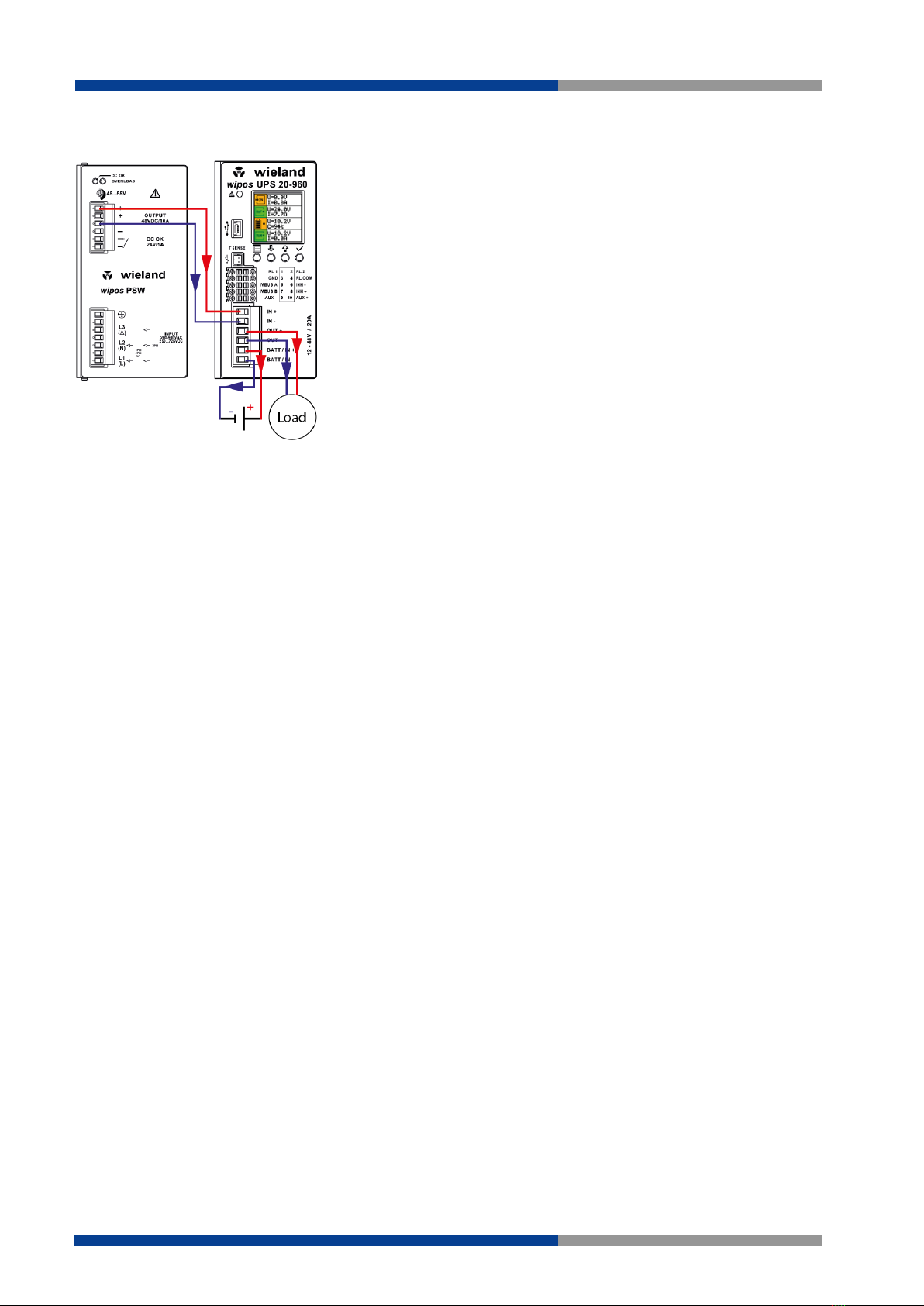
Lead acid and lithium batteries share the same 3 stages charging algorithm as shown on Figure 7.
Figure 7 Lead acid and Lithium charging algorithm
For nickel batteries, during maintenance, the UPS module gives pulses of 3 s every 30 s with a maximum
current of 1/10 of the battery charge current and maximum voltage equal to the battery charge voltage.
Figure 8 Nickel charging algorithm
For Supercapacitor after the constant current phase the algorithm goes directly to maintenance keeping
the voltage at battery charge voltage.
Figure 9 Figure 7: Supercapacitors charging algorithm
Time
Current
Voltage
Constant current Constant voltage Maintenance
Charge current
Charge voltage
Float voltage
Time
Current
Voltage
Constant current Constant voltage Maintenance
Charge current
Charge voltage
Time
Current
Voltage
Constant current Maintenance
Charge current
Charge voltage
5|Function description
Wieland Electric GmbH | BA001052 (Rev. A) | 11/2018 15
Warning!
In order to avoid potentially hazardous situations including fire hazard, safety recommendations must be followed.
Only authorized staff can install the unit.
Warning!
For Lithium cells the balancing and protection circuit must be included in the battery pack.
Warning!
For Nickel batteries the use of the external temperature sensor is mandatory. The sensor must be placed in contact
with the battery.
5.1.4 Coulomb counter
The UPS module measures the current flowing from / to the battery to keep track of the capacity available
on the battery. The capacity is measured in Ampere Hour [Ah]. The value shown is based on the following
assumptions:
•The value shown is just informative and does not represent the real state of charge of the battery
in some circumstances, for example if the battery is damaged.
•When the battery is connected for the first time or the system starts from OFF, the system as-
sumes the battery is fully discharged and start with 0 Ah counter.
•Once the battery is fully charged the system sets the counter to the nominal capacity specified
by the user. See no. 12 in section 6.2 for more details.
5.1.5 PC shutdown and automatic restart
PC shutdown: In case the UPS module is used to supply a PC it is possible to automatically shut down
the PC after an adjustable time of backup. For this the PC must run the user software and must be con-
nected through Modbus. Optionally the user software can call a task on the PC before shutting down, for
example to backup some sensitive data.
Automatic restart: UPS module is able to automatically restart a PC which was powered OFF by mistake,
for example in case of the Operating System (OS) crash. The user may adjust an output current threshold
and a timer used for detecting the PC OFF status. In order to restart the PC, the UPS module toggles the
output OFF and then ON again. User must enable in the PC BIOS the automatic start in case of supply
ON.
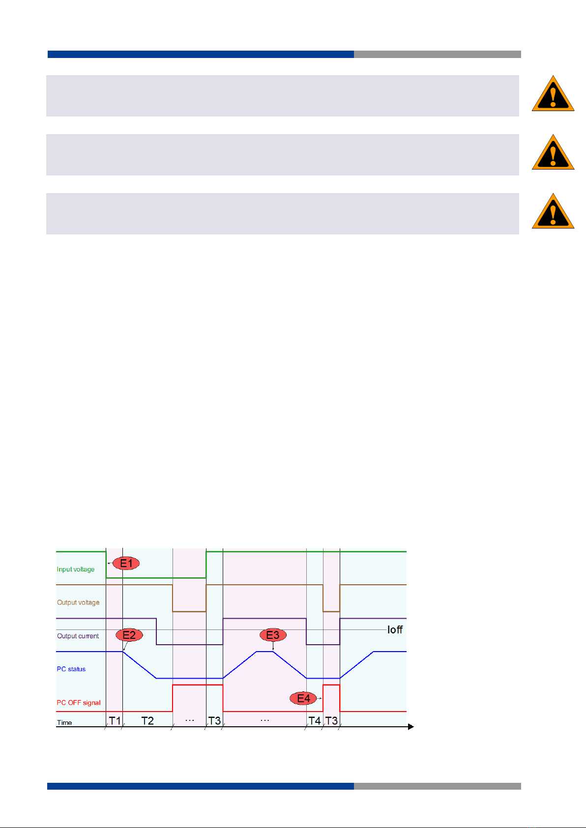
The diagram below shows the UPS module's behavior when Shutdown and Automatic restart is enabled.
Figure 10 Shutdown and restart chart
WARNING
WARNING
WARNING

5|Function description
Wieland Electric GmbH | BA001052 (Rev. A) | 11/2018 16
Parameter Name Description
E1
Backup
Power failure on the line happens. System enters backup
mode.
E2
Automatic PC shutdown
The user software sends a shutdown command to the PC.
Optionally: a task is called before shutdown.
E3
Unexpected PC shut-
down
The PC shutdowns in an unexpected way, for example
caused by OS crash.
E4
PC restart
The UPS module detects the PC being OFF because the
output current was lower than Ioff current threshold for T4
time. As a consequence, the UPS module generates an
ON->OFF->ON cycle on its output.
T1
PC shutdown delay
User settable (see no. 36 in section 6.2). Time between
start of backup and start of PC shutdown procedure.
T2
PC shutdown time
User settable (see no. 37 in section 6.2). Time between
start of shutdown procedure and output voltage OFF. This
time must be set longer than the maximum time the PC
takes to complete the shutdown.
T3
PC restart minimum
OFF
time
User settable (see no. 38 in section 6.2). T3 is the delay
used between the return of the input voltage and the acti-
vation of the output. The same time is used by the auto-
matic restart function as power OFF time to restart the PC.
The value must be big enough for the PC to detect the
supply ON->OFF->ON cycle to restart.
T4
PC
OFF
detection timer
User settable (see no. 40 in section 6.2). Minimum time at
which the output current must be below the Ioff current
threshold to trigger the automatic PC restart (PC supply
ON->OFF->ON cycle).
Ioff
PC
OFF
detection cur-
rent threshold
User settable (see no. 39 in section 6.2). Current threshold
used to detect PC OFF status. This value must be lower
than the minimum PC current consumption when this is
ON.
Table 1 Shutdown and restart
The parameters are settable through the UPS module user interface or using the user software. The
checkbox "Run on startup" must be checked in the user software when PC shutdown function is used.
To inhibit the software from calling the shutdown command, the user can select the "Inhibit shutdown"
check box.
5.1.6 Cold start
The cold start is a procedure that allows turning ON the UPS without the input power. This procedure is
used to turn ON the UPS to operate during a power interruption. This practice is also a method to see if
the battery connected to the UPS module is functional.
In cold start the UPS module will remain ON for at least 60 seconds independently from the battery
voltage (even when being under the deep discharge threshold), the inhibit input and the backup timer.
After the first 60 seconds the device stays ON until the battery is not deep discharged, the backup timer
is not expired or the inhibit input is not active.
When cold started, the "Cold start" text is written beside the input icon on the status screen.
If the input supply returns during cold start, the device reverts to normal operation.
To cold start the device the user has the following options:
•From front panel: Press and hold simultaneously the and buttons until you see the welcome
message on the screen.
•Remotely through inhibit input: When enabled on the user setting (see no. 32 in section 6.2),
the device can be cold stared toggling the inhibit status from true to false.

5|Function description
Wieland Electric GmbH | BA001052 (Rev. A) | 11/2018 17
•On battery connection: When enabled on the user settings (see no. 33 in section 6.2), the device
automatically cold starts when the battery, previously disconnected, is connected to the device.
5.1.7 Blink output on backup
When this option is enabled, during backup, the output voltage switches on/off periodically with the
timing defined on "Blink output on backup Ton" and "Blink output on backup Toff" (see no. 42 and no.
43 in section 6.2). This function may be used on illumination application where is necessary to inform the
person in the building that the lighting is running on batteries.
5.2 DC-DC mode
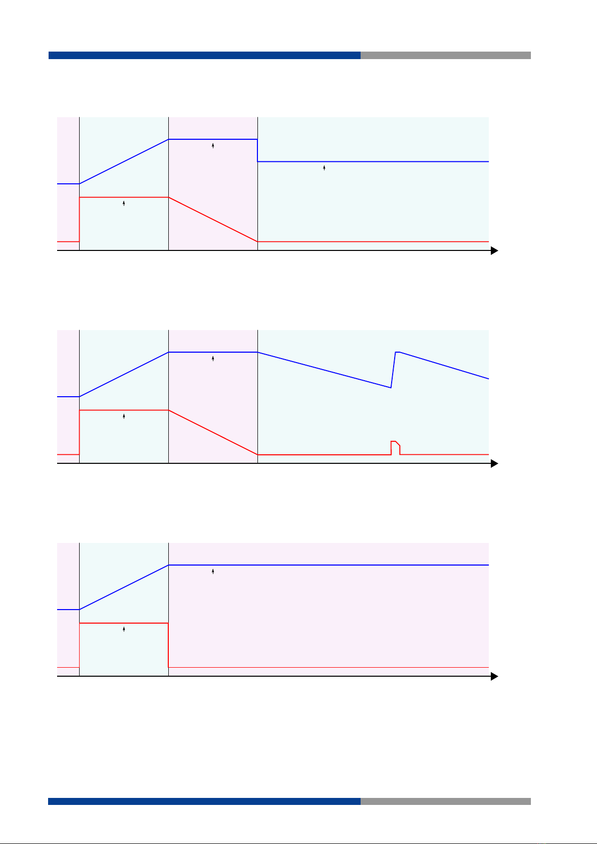
The UPS module can be used as a high performance DC-DC converter. An example of DC-DC connection
is given on Figure 11.
Any voltage between 10 V to 55 V can be converted to any voltage between 10 V to 55 V (step-up and
step-down operation) with up to 20 A input or output current.
Input and output are protected against over current with user settable limits. See section 5.3 for more
details.
When used as a DC-DC converter, the input supply must be connected to the battery connector as shown
on Figure 11.
Figure 11 DC-DC connection example

5|Function description
Wieland Electric GmbH | BA001052 (Rev. A) | 11/2018 18
5.3 Current limit
The UPS module has the ability to limit the current flowing through its input, output and battery terminals
to a user settable threshold.
5.3.1 Current limit in UPS mode
In UPS mode the UPS module provides 4 different settings for the current limit:
•Maximum input current (see no. 21 in section 6.2), default 20 A: it is used to limit the input
current at a specified threshold. For example, if the DC power supply is rated less than 20 A, the
threshold can be lowered to avoid too high current drain from the power supply. When the input
current limit is reached, the battery charging current is limited. If the input current cannot be kept
below the threshold due to excessive loading, an input overcurrent alarm is triggered. When the
input current is approaching the threshold, the measured input current is displayed with red fonts
on the LCD.
•Maximum output current (see no. 22 in section 6.2), default 20 A: it is used to limit the maximum
current delivered to the load. When the threshold is reached due to excessive loading, an output
overcurrent alarm is triggered. When the output current is approaching the threshold, the meas-
ured output current is displayed with red fonts on the LCD.
•Battery maximum charge current (see no. 7 in section 6.2), default 0.5 A (maximum settable
20 A): it is used to limit the maximum charge current supplied to the battery. This threshold will
be automatically reduced in such manner that the maximum input current limit (see no. 21 in
section 6.2) is distributed to the load with priority towards the charging.
For example, if the maximum input current limit is 20 A and the load needs 10 A while the maxi-
mum charge current is set at 12 A, the controller will limit the charging current automatically to
10 A until the load will need <10 A.
•Battery maximum discharge current (see no. 11 in section 6.2), default 20 A: it is used to limit
the maximum discharge current delivered from the battery during the backup function. When the
threshold is reached due to excessive loading, a battery overcurrent alarm is triggered and the
output voltage starts to decrease. When the battery discharge current is approaching the thresh-
old, the measured battery current is displayed with red fonts on the LCD.
5.3.2 Current limit in DC-DC mode
In DC-DC mode the UPS module provides 2 different settings for the current limit:
•Maximum input current (see no. 21 in section 6.2), default 20 A: it is used to limit the input
current at a specified threshold. For example, if the DC power supply is rated less than 20 A, the
threshold can be lowered to avoid too high current drain from the power supply. When the input
current limit is reached due to excessive loading, an input overcurrent alarm is triggered. When
the input current is approaching the threshold, the measured input current is displayed with red
fonts on the LCD.
•Maximum output current (see no. 22 in section 6.2), default 20 A: it is used to limit the maximum
current delivered to the load. When the threshold is reached due to excessive loading, an output
overcurrent alarm is triggered and the output voltage starts to decrease. When the output current
is approaching the threshold, the measured output current is displayed with red fonts on the LCD.
5.4 Inhibit
An opto-isolated input allows the inhibition of the backup function in UPS mode or switching off the
output on DC-DC mode. The polarity of the input can be defined using the "Inhibit polarity" field. See no.
28 in section 6.2 for more details.

5|Function description
Wieland Electric GmbH | BA001052 (Rev. A) | 11/2018 19
5.5 Modbus
The UPS module communicates through Modbus/RTU as specified on "MODBUS over Serial Line" and
"MODBUS APPLICATION PROTOCOL SPECIFICATION" documents available on http://www.mod-
bus.org/.
Table 2 contains the field types and Table 3 the mapped fields. For types bigger than 16 bit, access all
registers in one transaction (multiple register read or write) to ensure atomic operation.
Type Modbus function codes
Description
Read Write
BIT
1,2
5,15
Single bit with value 0 or 1
SINT16
3,4
6,16
Signed 16 bit value (2’s complement)
UINT16
3,4
6,16
Unsigned 16 bit value
SINT32
3
16
Signed 32 bit value (2’s complement) Composed of 2 consecutive
registers in big-endian order.
UINT32
3
16
Unsigned 32-bit value. Composed of 2 consecutive registers in
big-endian order.
DATE
3
16
Time and date field. Composed of 4 Modbus registers as follows:
Address offset Byte Description
0
MSB
Reserved, set to 0
LSB
Year-2000
1
MSB
Month (1=January)
LSB
Day of the month
2
MSB
Hour of the day (24h format)
LSB
Minutes
3
MSB
Milliseconds
LSB
Table 2 Modbus types
Address Type R/W Unit Min. Max. Description
Common
0x0010
DATE
R/W
R/W
Real time clock
Settings (see section 6.2)
0x1000
UINT16
R/W
1
1
247
Modbus address
0x1001
UINT16
R/W
1
1
5
Modbus baud rate
1: 9600 baud
2: 19200 baud
3: 38400 baud
4: 57600 baud
5: 115200 baud
0x1002
UINT16
R/W
1
1
3
Modbus parity
1: None
2: Even
3: Odd
0x1003
UINT16
R/W
1
1
2
Modbus stop bits
0x1010
UINT16
R/W
1
1
4
Battery type
1: Lead
2: Nickel
3: Lithium
4: Supercapacitor
0x1011
UINT16
R/W
0.1 V
10
58
Battery charge voltage

5|Function description
Wieland Electric GmbH | BA001052 (Rev. A) | 11/2018 20
Address Type R/W Unit Min. Max. Description
0x1012
UINT16
R/W
0.1 A
0.5
20
Battery charge current
0x1013
UINT16
R/W
0.1 V
10
58
Battery float voltage
0x1014
UINT16
R/W
0.1 V
5
58
Battery low voltage
0x1015
UINT16
R/W
0.1 V
5
58
Battery deep discharge voltage
0x1016
UINT16
R/W
0.1 A
5
21
Battery max. discharge current
0x1017
UINT16
R/W
0.1 Ah
1
200
Battery capacity - Supercap capacitance
0x1018
SINT16
R/W
1 °C
-40
60
Battery min. temperature
0x1019
SINT16
R/W
1 °C
-40
60
Battery max. temperature
0x101A
UINT16
R/W
1 kh
1
100
Battery lifetime
0x101B
UINT16
R/W
1
0
3
Ri alarm mode
0: Disabled
1: Fix
2: Automatic
3: Automatic done
0x101C
UINT16
R/W
0.1 m©
0
300
Ri nom
0x101D
UINT16
R/W
1%
50
300
Ri max. variation
0x1020
UINT16
R/W
1
1
2
Operating mode
1: UPS
2: DC-DC
0x1021
UINT16
R/W
0.1
10
58
Nominal output voltage
0x1022
UINT16
R/W
0.1
5
21
Max. input current
0x1023
UINT16
R/W
0.1
1
21
Max. output current
0x1024
UINT16
R/W
1
0
1
Max. Backup time enable
0: Disabled
1: Enabled
0x1025
UINT16
R/W
1 m
1
1440
Max. backup time.
0x1026
UINT16
R/W
1
0
1
Buzzer enable
0: Disabled
1: Enable
0x1027
UINT16
R/W
1
0
65535
Relay 1 configuration (see no. 27 in section
6.2)
0x1028
UINT16
R/W
1
0
65535
Relay 2 configuration (see no. 27 in section
6.2)
0x1029
UINT16
R/W
1
1
2
Inhibit polarity
1: Low
2: High
0x102A
UINT16
R/W
1
1
2
DC-DC output mode
1: Single
2: Parallel
0x102B
UINT16
R/W
1
0
1
Output enable
0: Disabled
1: Enabled
0x102C
UINT16
R/W
1
0
1
Aux enable
0: Disabled
1: Enabled
0x102D
UINT16
R/W
1
0
1
Cold start on inhibit toggle
0: Disabled
1: Enabled
0x102E
UINT16
R/W
1
0
1
Cold start on battery connection
0: Disabled
1: Enabled
0x1030
UINT16
R/W
1
0
1
PC shutdown enable
This manual suits for next models
1
Table of contents
Other Wieland UPS manuals


