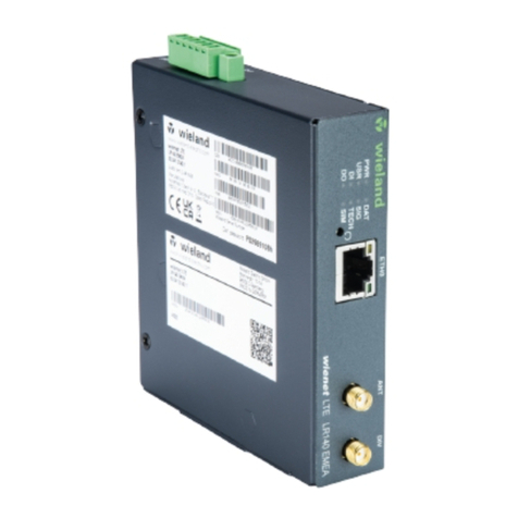
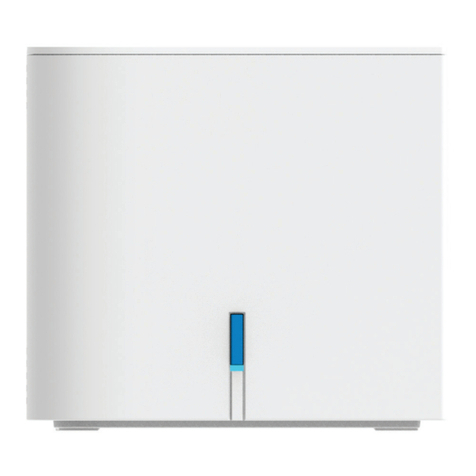
Wieland wienet LTE LR240 Technical manual

Betriebsanleitung (Original) / Operation instruction (translation from original)
wienet LTE LR240 EMEA 83.041.0240.1
wienet LTE LR241 EMEA 83.041.0241.1
LTE-Router
Wieland Electric GmbH
Brennerstraße 10
– 14
96052 Bamberg
Phone
+49 951 9324-0
Fax
+49 951 9324-198
info@wieland
-electric.com
www.wieland
-electric.com
Doc. # BA001285 – 05/2023 (Rev. B) wienet LTE LR240/LR241 EMEA 1 DE
HINWEIS
Personal, welches dieses Gerät installiert, programmiert, in Betrieb nimmt oder wartet,
muss diese Anleitung gelesen und verstanden haben.
VORSICHT
•Ggf. erforderliche Schutzmaßnahmen und Schutzeinrichtungen müssen den gültigen
Vorschriften entsprechen.
•Beschädigte Produkte dürfen weder installiert noch in Betrieb genommen werden. Im
Falle eines Defekts senden Sie das Gerät zurück an Wieland Electric.
•Nur in spannungsfreiem Zustand anschließen oder trennen!
•Führen Sie keine Fremdobjekte in das Gerät ein!
•Halten Sie das Gerät von Wasser und Feuer fern!
Entsorgung
Die Entsorgung unbrauchbarer oder irreparabler Geräte muss immer gemäß den jeweils
gültigen landesspezifischen Entsorgungsvorschriften (z. B. europäischer Abfallschlüssel
16 02 04) erfolgen.
1Funktionsbeschreibung
Der LTE-Router ist ein kompaktes elektronisches Gerät, das eine sichere Datenübertragung
mittels kabelgebundener oder kabelloser Netzwerk-Technologien ermöglicht. Das erlaubt
eine Fernwartung von angeschlossenen Geräten zu jeder Zeit und von jedem Ort aus.
•Anschluss von verschiedenen Geräten über RJ45, serielle und digitale Schnittstellen.
•Aufbau von sicheren VPN-Verbindungen
2Frontansicht
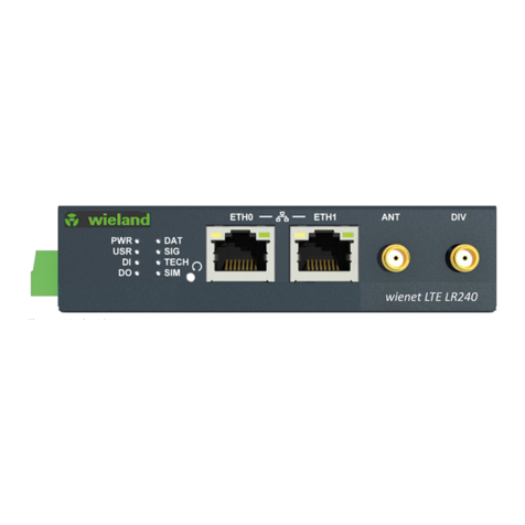
Siehe Abb. 1 und 2.WIFI-Stecker optional.
LED
Farbe
Zustand LED
Beschreibung
PWR
grün
LED ist an.
Der Router wird gestartet.
LED blinkt.
Der Router ist bereit.
LED blinkt schnell.
Firmware-Update
USR
grün
–
Kann der User belegen.
DI
grün
LED ist an.
Der erste Binäreingang ist aktiv.
DO
grün
LED ist an.
Der zweite Binäreingang ist aktiv.
DAT
grün
LED blinkt.
Kommunikation läuft über Mobilfunk.
SIG
grün
LED ist an.
Gutes Signal
LED blinkt.
Mittelmäßiges Signal
LED blinkt schnell.
Schlechtes Signal
TECH
grün
LED ist an.
Aktive SIM verwendet 4G-Technologie.
LED blinkt.
Aktive SIM verwendet 3G-Technologie.
LED blinkt schnell.
Aktive SIM verwendet 2G-Technologie.
SIM
grün
LED ist an.
SIM1 ist gewählt.
LED blinkt.
SIM2 ist gewählt.
LED blinkt schnell.
SIM-Karten-Fehler (fehlende SIM oder PIN
nicht eingegeben).
ETH0 / ETH1
grün
LED ist an.
Ausgewählte Bitrate 100 Mbps
LED ist aus.
Ausgewählte Bitrate 10 Mbps
ETH0 / ETH1
orange
LED ist an.
Netzwerkkabel ist angeschlossen.
LED blinkt.
Datenübertragung
LED ist aus.
Netzwerkkabel ist nicht angeschlossen.
3Montage und Demontage
Montage (siehe Abb. 5)
Demontage (siehe Abb. 6)
1. Befestigungsclip für Hutschiene mit drei
Schrauben am Gerät festschrauben.
2.
Gerät auf die Hutschiene einhängen.
3.
Durch leichten Druck in Pfeilrichtung
Gerät auf die Hutschiene aufschnappen.
4. Gerät in Pfeilrichtung herunterdrücken.
5.
Im heruntergedrückten Zustand Gerät in
Pfeilrichtung aus der Verrastung lösen
und von der Hutschiene nehmen.
6. Schrauben am Befestigungsclip lösen.
4Anschlussbelegung und Verdrahtung
24 V DC Versorgung, siehe Abb. 4
Pin-
Nr.
Signal-bezeichnung Beschreibung
1
PWR (+)
Positiver Pol der DC Versorgungsspannung (+9 … +48 V DC)
2
PWR (-)
Negativpol der DC Versorgungsspannung (+9 … +48 V DC
HINWEIS
•Die Erdungsschraube befindet sich schräg links über der Anschlussbuchse.
•Das Gerät muss von einer Stromversorgung gespeist werden, die als "Limited Power
Source" (LPS) oder CEC/NEC Class 2 spezifiziert ist.
Binäre Ein- und Ausgänge
Pin-Nr.
Signalbezeichnung
Beschreibung
3
IN (+)
Binäreingang
4
IN (-)
Binäreingang
5
OUT (+)
Binärausgang
6
OUT (-)
Binärausgang
IN
Siehe Abb. 7.
Serielle Schnittstellen
Ausführung
Pin-Nr.
Signalbezeichnung
Beschreibung
RS485
1
D (+)
IN / OUT
RS485
2
D (-)
IN / OUT
RS485
3
GND
Ground
RS232
3
GND
Ground
RS232
4
RXD
Received Data
RS232
5
TXD
Transmit Data
RS232
6
RTS
Request to Send
RS232
7
CTS
Clear to Send
5Einlegen der SIM / SD-Karte
1. Lösen Sie die Schrauben an der Abdeckung und nehmen Sie die Abdeckplatte ab.
2.
Schieben Sie die SIM / microSD-Karte in den SIM-/ SD-Karten-Slot auf der Rückseite ein,
siehe Abb. 3.
6Antennen
Schließen Sie die Antennen Main (ANT) und Diversity (DIV) über SMA-Anschlüsse an.
Anzugmoment: 0,9 Nm.
7Werkseinstellungen (Reset)
Der Reset-Knopf ("RST", Rückseite) stellt die Werkseinstellungen inkl. IP-Adresse und
Zugangsdaten wieder her. Drücken Sie den Reset-Knopf für min. 4 s bei eingeschaltetem
Router. Die LED "PWR" schaltet sich aus und wieder ein. Beachten Sie dann den Abschnitt 8
"Zugriff auf den Router".
8Zugriff auf den Router
1. Verbinden Sie Ihren PC via Ethernet-Kabel mit dem Router (Port "ETH0").
2. Ändern Sie die Netzwerkeinstellungen am PC so, dass dieser automatisch eine IP-Adresse
erhält.
3. Der Router wird via Web-Browser parametriert. Logindaten zur Web-Oberfläche:
Adresse:
http://192.168.1.1
Benutzername:
root
Passwort: siehe Etikett am Produkt
Pxxxxxxxxh
9Technische Daten
Anschlussdaten
Eingangsspannung
9 … 48 V DC
Leistungsaufnahme (Ruhe / typ. / max.)
2 W / 3,5 W / 10 W
1× binärer Eingang
36 V / 0.5 mA
1× binärer Ausgang
Open Drain, 36 V / 100 mA
Eingangsspannung Signal 0 / 1
≤ 0.8 V (0.5 mA)) / ≥2 V
Max. Ausgangslast
100 mA bei 9 … 48 V
Serielle Schnittstellen
1× RS232 (Tx, Rx, GND, RTS, CTS)
1× RS485 (A(-), B(+), GND)
Funktechnologie
4G LTE Cat 4; WIFI (LR241)
WIFI-Daten
Antenne
1× R-SMA-Stecker
Standards
IEEE802.11 ac/b/g/n 2.4 GHz / 5 GHz
Sicherheit
WEP, TKIP, AES, WPA, WPA2, 802.1X
Modi
Access Point (bis zu 8 Clients), Station, Multirole
STA & AP
Allgemeine Daten
Betriebsumgebungstemperatur
-40 … +75 °C
Lagertemperatur
-40 … +85 °C
Relative Luftfeuchtigkeit
5 … 95 %, nicht kondensierend
Schutzart
IP30
Montageart
DIN-Hutschiene 35 mm, Wandmontage
Gehäuse
Metallgehäuse
Abmessungen / Gewicht
103 × 95 × 25 mm, siehe Abb. 8 / 345 g
Antennenanschlüsse (ANT, DIV)
2× SMA-Buchse (1× Main, 1× Diversity)
Benutzerschnittstelle
ETH0/ETH1
IP-Adresse / NetMask (ETH0)
2× Ethernet (1+ 1), RJ45, 10/100 Mbps
192.168.1.1 / 255.255.255.0
PWR & I/O / SERIAL
6-poliger Connector / 7-poliger Connector
Anschlussquerschnitt (6-/7-polig)
max. 1,5 mm²
Abisolierlänge
max. 5 mm
Frequenzbänder;
Sendeleistung
FDD
TDD
UMTS/HSPA+
GPRS/EDGE
Wi-Fi
700 / 800 / 900 / 2600 / 1800 / 2100 MHz, Power
2500 / 2300 / 2600 MHz
900 / 2100 MHz; max. Power 25 dBm
900 / 1800 MHz; max. Power 33 dBm
2,4/5 GHz; max. Power 17,3 dBm
microSD-Karte
2× SIM (Micro SIM – 3FF); 15,0 × 12,0 × 0,76 mm
Normen
CE
CE: Hiermit erklärt Wieland Electric GmbH, dass das Produkt wienet LTE LR240 EMEA mit
den folgenden europäischen Anforderungen übereinstimmt: RED Richtlinie 2014/53/EU,
RoHS-Richtlinie 2011/65/EU. Die vollständige EU-Konformitätserklärung ist mit der
jeweiligen Teilenummer unter z. B. https://eshop.wieland-
electric.com/products/83.041.0240.1 im Register "Downloads" abrufbar.
10 Mitgeliefertes Zubehör
Befestigungsclip für Hutschiene
5
6
7
8
1
2
3
4

Installation instruction (translation from original)
wienet LTE LR240 EMEA 83.041.0240.1
wienet LTE LR241 EMEA 83.041.0241.1
LTE Router
Wieland Electric GmbH
Brennerstraße 10
– 14
96052 Bamberg
Phone
+49 951 9324-0
Fax
+49 951 9324-198
info@wieland
-electric.com
www.wieland
-electric.com
Doc. # BA001285 – 05/2023 (Rev. B) wienet LTE LR240 EMEA 2 EN
NOTE
Personnel which installs, programs, operates or maintains this device must have read and
understood these instructions.
CAUTION
•Protective measures and mechanisms must correspond to applicable regulations.
•Damaged products must neither be installed nor put into operation. In case of a defect,
please return the device to Wieland Electric.
•Only connect or disconnect the device when de-energized!
•Do not insert any objects into the device!
•Keep the device away from water and naked flames!
Disposal
The disposal of unusable or irreparable devices should always be done in accordance with
the respectively valid country-specific waste-elimination guidelines (e.g. European Waste
Code 16 02 14).
1Function description
The LTE router is a compact electronic device that facilitates a data connection by using
cable based or wireless network technologies. This enables remote maintenance of
connected devices at any time, from anywhere.
•Connection of different devices via RJ45, serial and digital interfaces.
•Establishment of secure VPN connections.
2Front view
See Fig. 1 and 2.
LED
Color
State of LED
Description
PWR
green
LED on
The router is being started.
LED flashes
The router is ready.
LED flashes rapidly
Firmware update
USR
green
–
Can be assigned by the user.
DI
green
LED on
The first binary input is active.
DO
green
LED on
The second binary input is active.
DAT
green
LED on
Communication via radio channel
SIG
green
LED on
Good signal
LED flashes
Fair signal
LED flashes rapidly
Poor signal
TECH
green
LED on
4G technology is used by the active SIM.
LED flashes
3G technology is used by the active SIM.
LED flashes rapidly
2G technology is used by the active SIM.
SIM
green
LED on
First SIM card active
LED flashes
Second SIM card active
LED flashes rapidly
SIM card problem (missing SIM or PIN not entered)
ETH0 /
ETH1
green
LED on
Selected 100 Mbps bit rate
LED off
Selected 10 Mbps bit rate
ETH0 /
ETH1
orange
LED on
The network cable is connected.
LED flashes
Data transmission
LED off
The network cable is not connected.
3Mounting and removal
Mounting (see Fig. 5)
Removal (see Fig. 6)
1. Attach the fixing clip of the DIN rail (top
hat rail) to the device with three screws.
2.
Attach the device to the DIN rail.
3.
Snap the device onto the DIN rail by
applying slight pressure in the direction of
the arrow.
4. Press the device down in the direction of
the arrow.
5.
While it is pressed down, detach the
device from the latching (in the direction
indicated by the arrow) and remove it
from the DIN rail.
6. Unscrew the screws from the fixing clip.
4Connection assignment and wiring
24 V DC supply, see Fig. 4
Pin no.
Signal designation
Description
1
PWR (+)
Positive terminal of the DC power supply (+9 … +48 V DC)
2
PWR (-)
Negative terminal of the DC power supply (+9 … +48 V DC)
NOTE
•The grounding screw is located diagonally on the left above the connection socket.
•The device must be powered by a power supply that is specified as a "Limited Power
Source" (LPS) or CEC/NEC Class 2.
Binary inputs and outputs
Pin no.
Signal designation
Description
3
IN (+)
Binary input
4
IN (-)
Binary input
5
OUT (+)
Binary output
6
OUT (-)
Binary output
IN
See Fig. 7.
Serial Interfaces
Model
Pin no.
Signal designation
Description
RS485
1
D (+)
IN / OUT
RS485
2
D (-)
IN / OUT
RS485
3
GND
Ground
RS232
3
GND
Ground
RS232
4
RXD
Received Data
RS232
5
TXD
Transmit Data
RS232
6
RTS
Request to Send
RS232
7
CTS
Clear to Send
5Inserting SIM / SD micro-card
1. Unscrew the screws from the cover and remove the cover plate.
2. Insert the SIM/microSD card into the SIM/SD card slot on the back, see Fig. 3.
6Antennas
Connect the Main (ANT) and Diversity (DIV) antennae via the SMA connectors.
Tightening torque: 0.9 Nm.
7Factory settings (reset)
The reset button ("RST", on the back) resets the factory settings, including the IP address
and access data. Push the reset button for at least 4 seconds while the router is switched on.
The LED "PWR" switches off and on again. Then, see section 8 "Access to the router".
8Access to the router
1. Connect your PC to the router ("ETH0" port) via Ethernet cable.
2. Change the network settings on the PC so that it automatically receives an IP address.
3. The router is parametrized via WEB browser. Login details for web interface:
Address:
http://192.168.1.1
User name:
root
Password: see product label
Pxxxxxxxxh
9Technical data
Connection Data
Input voltage
9 … 48 V DC
Consumption (idle / average / peak.)
2 W / 3,5 W / 10 W
1× binary input
36 V / 0.5 mA
1× binary input
Open Drain, 36 V / 100 mA
Input voltage signal 0 / 1
≤ 0.8 V (0.5 mA)) / ≥ 2 V
Max. output load
100 mA bei 9 … 48 V
Serial Interfaces
1× RS232 (Tx, Rx, GND, RTS, CTS)
1× RS485 (A(-), B(+), GND)
Technology
4G LTE Cat 4; WIFI (LR241)
WIFI data
Antenna
1× R-SMA connector / 4G LTE Cat 4; WIFI
Standards
IEEE802.11 ac/b/g/n 2.4 GHz / 5 GHz
Security
WEP, TKIP, AES, WPA, WPA2, 802.1X
Modes
Access Point (up to 8 clients), Station, Multirole
STA & AP
General data
Operating environment temperature
-40 … +75 °C
Storage temperature
-40 … +85 °C
Relative humidity
5 … 95 %, non-condensing
Degree of protection
IP30
Mounting method
DIN rail 35 mm, wall mounting
Housing
Metal box
Dimensions / Weight
103 × 95 × 25 mm, see Fig. 8 / 345 g
Antenna connectors (ANT, DIV)
2× SMA socket (1× Main, 1× Diversity)
User interface
ETH0/ETH1
IP Address / NetMask (ETH0)
2× Ethernet (1+ 1), RJ45, 10/100 Mbps
192.168.1.1 / 255.255.255.0
PWR & I/O
6-pole connector
SERIAL
7-pole connector
Connector cross section (6-/7-pole)
max. 1.5 mm²
Wire strip length
max. 5 mm
Frequency bands;
Transmission power
FDD
TDD
UMTS/HSPA+
GPRS/EDGE
Wi-Fi
700 / 800 / 900 / 2600 / 1800 / 2100 MHz, Power
2500 / 2300 / 2600 MHz
900 / 2100 MHz; max. Power 25 dBm
900 / 1800 MHz; max. Power 33 dBm
2,4/5 GHz; max. Power 17,3 dBm
microSD card
2× SIM (Micro SIM – 3FF); 15.0 × 12.0 × 0.76 mm
Standards
CE
CE: Hereby, Wieland Electric GmbH declares that the wienet LTE LR240 EMEA is in
compliance with the following European directives: RED directive 2014/53/EU, RoHS
directive 2011/65/EU. The complete EU Declaration of Conformity is available with the
respective part number under e.g. https://eshop.wieland-
electric.com/products/83.041.0240.1 in the register "Downloads".
10 Included accessories
Fixing clip for DIN rail
UKCA – for UK: Wieland Electric Ltd | Ash House, Tanshire Park | Shackleford Road | Elstead, Godalming GU8 6LB
5
6
7
8
1
2
3
4
Other manuals for wienet LTE LR240
1
This manual suits for next models
2
Table of contents
Languages:
Other Wieland Wireless Router manuals
