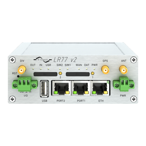
Wieland wienet LR77 v2 User manual

User manual
Doc. no. BA000868
Last updated: 08/2021 (Rev. C)
wienet
LR77 v2
M
obile router LT E

Info
Wieland Electric
GmbH | BA000868 | 08/2021 (Rev. C)
2
INFO
This document is copyright-protected. The rights derived from this copyright are reserved for Wie-
land Electric. Reproduction of this document or parts of this document is only permissible within the
limits of the statutory provision of the Copyright Act. Any modification or abridgment of the docu-
ment is prohibited without the express written agreement of Wieland Electric.
wienet is a trademark of Wieland Electric. Other product or brand names mentioned in this docu-
ment are brand trademarks or registered trademarks of their respective owners. Usage of these
names and trademarks by third parties for their own purposes could violate the rights of the owners.

Table of contents
Wieland Electric
GmbH | BA000868 | 08/2021 (Rev. C)
3
TABLE OF CONTENTS
1 About this document 5
1.1 Function of this document 5
1.2 Scope and revision level 5
1.3 Target group 5
1.4 Other applicable documents 5
1.5 Symbols and notations 6
2 Safety instructions 7
2.1 Qualified persons 7
2.2 General safety instructions 7
3 Router description 8
3.1 Introduction 8
4 Scope of delivery 9
5 Router design 10
5.1 Version 10
5.2 Article numbers 11
5.3 Basic dimensions of the metal housing 12
5.4 Mounting recommendations 13
5.5 Removal from DIN rail 14
5.6 User interfaces (connectors) 14
5.6.1 LED status indicators 15
5.6.2 Power connector PWR 16
5.6.3 Antenna connector ANT 17
5.6.4 SIM card reader 18
5.6.5 Ethernet port ETH 19
5.6.6 PORT1 20
5.6.7 PORT2 20
5.6.8 USB port 20
5.6.9 I/O port 21
5.6.10 Reset and reboot 22

Table of contents
Wieland Electric
GmbH | BA000868 | 08/2021 (Rev. C)
4
6 First use 23
6.1 Connecting the router before first use 23
6.2 Start the router 23
6.3 Router configuration 23
6.3.1 Configuration over Web browser 23
6.3.2 Configuration over SSH or Telnet 25
7Technical data 26
7.1 Technical data of the router 26
7.2 Technical data of mobile modules 27
7.2.1 Technical data of LTE module supporting 450 MHz 27
7.2.2 Technical data of GPS 28
7.3 Technical data of processor 28
7.4 Technical data of I/O port 28
7.5 Technical data of expansion port 28
8Maintenance and troubleshooting 29
8.1 Maintenance 29
8.2 Troubleshooting 29
8.3 FAQ 29
9Product disposal 31
10 Service and support 32

About this document
Wieland Electric
GmbH | BA000868 | 08/2021 (Rev. C)
5
1ABOUT THIS DOCUMENT
Please read this chapter carefully before working with this users guide and the wienet mobile router.
1.1 Function of this document
In this wienet mobile router User manual, the device and the functions of it are described. Use the
User manual, especially for the configuring of the mobile router.
This User manual guides the technical staff of router installer on installation, programming, opera-
tion and diagnosis of wienet router.
Chapter 2 Safety Instructions, p. 7, contain basic safety instructions. Please read and follow these
instructions in each case.
1.2 Scope and revision level
This User manual is valid for the products wienet VPN router, which are associated with this User
manual. The installation instructions accompanying the product is downloadable on the Wieland
website. Be sure to always use the information provided in the current version of this User manual.
The version and revision level can be seen in the title page and the footer.
1.3 Target group
This manual is aimed at planners, engineers, installers and service personnel who are planning a re-
mote control or remote maintenance solution and put into operation.
1.4 Other applicable documents
You can also use our website eshop.wieland-electric.com. You can also download the following files:
•Product information wienet router and switches
•Data sheets wienet router
•Technical notes about Wie-Service24.com (VPN Server portal)
Document Title Article number
User manual
Manual wienet Router v2 – Extension ports
BA000917
Configuration manual
wienet v3 Configuration – Cellular router
BA001039
Installation instructions
Installation instructions wienet 4G LTE LR77
BA000866
NOTICE

About this document
Wieland Electric
GmbH | BA000868 | 08/2021 (Rev. C)
6
1.5 Symbols and notations
The symbol "DANGER" indicates imminent danger. If it is not avoided, it can result in death or seri-
ous injury.
"DANGER" is used to warn of dangers at the time of the warning are already existing (e.g. hot sur-
faces, sharp edges, pinch points, etc.).
It is used exclusively in danger of personal injury!
The symbol "WARNING" indicates a potential threat. If it is not avoided, it can result in death or seri-
ous injury could result.
The symbol "CAUTION" indicates a potential threat. If it is not avoided, slight or minor injury can re-
sult.
Refer to notes for special features of a device.
Instructions also tell you about a potentially harmful situation. If it is not avoided, the system can be
damaged or something in its environment.
DANGER
WARNING
CAUTION
NOTICE

Safety instructions
Wieland Electric
GmbH | BA000868 | 08/2021 (Rev. C)
7
2SAFETY INSTRUCTIONS
This chapter is for your safety and the safety of equipment operators. Please read this chapter care-
fully before working with a VPN-Router.
General safety
•Personnel which install, program, operate or maintain this device must have read and understood
these instructions.
•The personnel must be thoroughly familiar with all warnings, instructions and requirements con-
tained in this manual.
•The applicable local safety, protection and installation requirements must be observed.
•The user is solely responsible for selecting the correct product and the technical design in accord-
ance with appropriate local regulations.
2.1 Qualified persons
wienet VPN router must be installed by competent persons only, configured in operation, commis-
sioned and maintained. Qualified is, who:
•has an appropriate technical training and
•has access to the wienet VPN router installation manuals, and this has been read and under-
stood.
2.2 General safety instructions
Please, observe the following instructions:
•The router must be used in compliance with all applicable international and national laws and
in compliance with any special restrictions regulating the utilization of the router in prescribed
applications and environments.
•To prevent possible injury to health and damage to appliances and to ensure that all the rele-
vant provisions have been complied with, use only the original accessories. Unauthorized modi-
fications or utilization of accessories that have not been approved may result in damage to the
router and in a breach of applicable regulations. Unauthorized modifications or utilization of
accessories that have not been approved may result in the termination of the validity of the
guarantee.
•The router cannot be opened.
•Before handling the SIM card, turn off the router and disconnect it from power supply.
•Caution! The SIM card could be swallowed by small children.
•Input voltage must not exceed 36 V DC max.
•Do not expose the router to extreme ambient conditions. Protect the router against dust, mois-
ture and high temperature.
•The router should not be used at petrol stations. We remind the users of the duty to observe the
restrictions concerning the utilization of radio devices at petrol stations, in chemical plants, or
in the course of blasting works in which explosives are used.
•Switch off the router when travelling by plane. Utilization of the router in a plane may endanger
the operation of the plane or interfere with the mobile telephone network, and may be unlaw-
ful. Failure to observe these instructions may result in the suspension or cancellation of tele-
phone services for the respective client, or, it may result in legal sanctions; it may also result in
both eventualities.
•When using the router in the close proximity of personal medical devices, such as cardiac pace-
makers or hearing aids, you must proceed with heightened caution.
•The router may cause interference when used in close proximity to TV sets, radio receivers or
personal computers.
•It is recommended that you should create an appropriate copy or backup of all the important
settings that are stored in the memory of the device.
WARNING
CAUTION

Router description
Wieland Electric
GmbH | BA000868 | 08/2021 (Rev. C)
8
3ROUTER DESCRIPTION
3.1 Introduction
LTE LR77 v2 router is used to wirelessly connect various equipment and devices via Ethernet inter-
face 10/100 to the Internet or intranet. Thanks to high data transfer speed, up to 100 Mbit/s (down-
load) and upload speed up to 50 Mbit/s, it is an ideal wireless solution for traffic and security camera
systems, individual computers, LAN networks, automatic teller machines (ATM) and other self-ser-
vice terminals and machines. Routers LR77 v2 are intended for use in the 450 MHz band whose main
advantage is the long range. The lower frequency, the less transmitters are needed for covering.
As a standard, this LR77 v2 wireless router is equipped with one Ethernet 10/100, one USB Host port,
one binary Input/output (I/O) port and one SIM card. To save and backup communication data, a
version with two SIM cards is available. The wide range of interface options of the router further ex-
pands an optional Port1 and Port2 – selected by the customer – for example Ethernet port 10/100,
serial interface ports RS232/RS485/RS422/MBUS or (I/O – CNT). For Port1 are available: Ethernet
port 10/100, serial interface ports RS232, RS485, RS422, or inputs/outputs (I/O ). Port2 may be
equipped with serial interfaces RS232, RS485, RS422, or inputs/outputs (I/O .
Product Version ETHERNET
I/O USB Host PORT1 PORT2 SIM1 SIM2
LR77 v2
Basic version
–
–
LR 77 v2c Compact
version
- -
-
LR77 v2f
Full version
Configuration is done via web interface protected by password. The LR77 LTE router supports crea-
tion of VPN tunnels using technologies IPsec, OpenVPN, L2TP to ensure safe communication. The
Web interface provides detailed statistics about the router activities, signal strength, detailed log,
etc. Cellular router supports functions: DHCP, NAT, NAT-T, DynDNS, NTP, VRRP, control by SMS and
many other functions.
Other diagnostic functions ensuring continuous communication include automatic inspection of
PPP connection offering an automatic restart feature – in case of connection losses, or hardware
watchdog which monitors the status of the router. With the help of a special window (startup script
window) you may insert Linux scripts for various actions. For some applications the key option to
create several different configurations for one LTE wireless router, the so-called profiles (maximum
of 4), and the option to switch between them (for example via SMS, binary input status, etc.) is es-
sential. Cellular wireless routers may automatically upgrade configuration and firmware from
server. This allows mass reconfiguration of many routers in one time.
The router also supports additional software for permanent traffic monitoring of routers or commu-
nication VPN server Wie-Service24.
Examples of possible applications
•remote support industry
•mobile office
•fleet management
•security system
•telematic
•telemetric
•remote monitoring
•vending and dispatcher

Scope of delivery
Wieland Electric
GmbH | BA000868 | 08/2021 (Rev. C)
9
4SCOPE OF DELIVERY
Basic delivery set of the router includes:
•router
•external antennas
•clips for the DIN rail
•assembly instruction
In addition to the basic components the following items can be ordered:
•Accon NetLink Pro – MPI to Ethernet adapter for S7-Remote-Support
•different antennas
•power supply

Router design
Wieland Electric
GmbH | BA000868 | 08/2021 (Rev. C)
10
5ROUTER DESIGN
5.1 Version
Table 1: Versions
Product Housing ETHERNET
I/O USB Host PORT1 PORT2 SIM1 SIM2
LR77 v2 SL
Metal
–
–
LR77 v2c SL
Metal
-
-
-
LR77 v2f SL
Metal
= Standard
= optional with interface modules
Table 2: Port1 options
Module can be connected as follows
PORT1
RS-232, RS-485/422, Ethernet, M-Bus, CNT, 3-Port-Switch (together with PORT2)
PORT2
RS-232, RS-485/422, M-Bus, WIFI/WLAN, 3-Port-Switch (together with PORT1)
Figure 1: Front panel LR77 v2B SL
Figure 2: Front panel LR77 v2F SL

Router design
Wieland Electric
GmbH | BA000868 | 08/2021 (Rev. C)
11
5.2 Article numbers
Basic version
Mobile router LTE wienet LR77 v2 SL
wienet mobile router GSM/GPRS/EDGE/UMTS/LTE; metal housing; SIM-
card-Slot; Interface: Ethernet 10/100 Mbit/s, USB 2.0 Type A Host,
1 digital input/1 digital output; Antenna connector SMA-50 Ohm; Max.
Download 100 MBit/s; Max. Upload 50 MBit/s; Supply voltage:
DC 10–30 V; Functions: openVPN, IPsec, DHCP (Client/Server), Web-In-
terface, FTP, NAT, PAT, SNMP, VRRP, DynDNS, NTP, SSH, SMS, eMail,
automatic update
Article number Port 1 Port 2 Housing
83.041.0050.1
–
–
Metal
83.041.0055.1
Ethernet
–
Metal
Full version
Mobile router LTE wienet LR77 v2f SL
wienet mobile router LTE , metal housing, 2 SIM-card-Slots, Interface:
Ethernet 10/100 Mbit/s, USB 2.0 Type A Host, 1 digital input/1 digital
output, Antenna connector SMA-50 Ohm, Max. Download 100 MBit/s,
Max. Upload 50 MBit/s, Supply voltage: DC 10–30 V, Functions: open-
VPN, IPsec, DHCP (Client/Server), Web-Interface, FTP, NAT, PAT, SNMP,
VRRP, DynDNS, NTP, SSH, SMS, eMail, automatic update
Article number Port 1 Port 2 Housing
83.041.0500.1
–
–
Metal
83.041.0505.3
Ethernet
–
Metal
83.041.0565.3
ETH
WIFI/WLAN
Metal

Router design
Wieland Electric
GmbH | BA000868 | 08/2021 (Rev. C)
12
Accessories
wienet antenna 15863V2 DACH ANT
wienet omni-roof antenna - Outdoor antenna
Frequency range: GSM/GPRS/EDGE/UMTS/LTE/5G/
LoRaWAN/NB-IoT,
Cable length: 5 m, Dimensions:. 82×48×48 mm
F0.000.0035.1
wienet antenna 15862V2 PANEL ANT.
wienet panel antenna
Frequency ranges: 2G, 3G, 4G
F0.000.0037.6
MPI-ETH ADAPTER ACCON-NETLINK-PRO
ACCON-NetLink-PRO compacts a handy communica-
tion and programming adapter between PC and S7
controllers.
F0.000.0031.8
5.3 Basic dimensions of the metal housing
Figure 3: Basic dimensions of the metal housing

Router design
Wieland Electric
GmbH | BA000868 | 08/2021 (Rev. C)
13
5.4 Mounting recommendations
•Possibility to be put on a work surface,
•DIN rail with clips CPD2 (Elpac clip SL for SL version) are included
For the most of applications with a built-in router in a switch board it is possible to recognize two
kinds of environments:
•no public and industry environment of low voltage with high interference,
•public environment of low voltage without high interference.
•For both of these environments it is possible to mount router to a switch board, the following
there is no need to have examination immunity or issues in connection with EMC according to EN
60439-1 ed.2:00 + A1:04.
•For compliance of EN 60439-1 ed.2:00 + A1:04 specification it is necessary to observe next assem-
bly of the router to the switchboard.
•For whip antennas we recommend to observe a distance of 6 cm from cables and metal surfaces
on every side according to the next picture due to the elimination of interference, while using an
external antenna except for the switch-board it is necessary to fit a lightening conductor,
•Before mounting a router on sheet-steel we recommend using an external antenna.
Figure 4: Space around antenna
For multiple cables, we recommend to bind the bunch according to the following picture. We recom-
mend for this use:
•Length of the bunch (combination of power supply and data cables) can be maximum 1,5 m, if the
length of data cables exceeds 1,5 m or in the event of, the cable leads towards the switchboard,
we recommend installing over-voltage protectors (surge suppressors).
•Keep a distance of 50 mm between data cables and power supply cables with ~ 230 V/50 Hz.
•All signals to sensors must be twisted pairs
Figure 5: Cable routing
CAUTION
CAUTION

Router design
Wieland Electric
GmbH | BA000868 | 08/2021 (Rev. C)
14
In front of individual connectors, sufficient space must be left for handling of cables.
Figure 6: Space in front of the connectors
For correct function of the router, we recommend to use in the switch-board earth-bonding distribu-
tion frame for grounding of power supply of router, data cables and antenna.
5.5 Removal from DIN rail
The DIN rail clip is suitable for a DIN rail according to EN 60715 standard only. The default position of
plastic or metal rail clip, which is used for mounting the router on a DIN rail, is shown in the follow-
ing figure. Its position can be changed on some models (back or bottom).
When changing the position of the DIN rail clip, tighten the screws with max. 0.4 Nm torque.
Figure 17: Default position of plastic and metal DIN rail clip.
To remove the router from the DIN rail, push the router down lightly, so the bottom part of the DIN
rail clip (hitched to the DIN rail) gets out of the rail and then pull out the bottom part of the router
away from the DIN rail.
5.6 User interfaces (connectors)
On the front panel, the following is located:
Name Connector Description
PWR
2-pin
Connector for the power supply
ETH
RJ-45
Connector for into the local area network
Port1
RJ-45
Connector for equipment over RS-232, RS-485/422, Ethernet, M-
Bus, CNT or XC-SW
Port2*
RJ-45
Connector for equipment over RS-232, RS-485/422, Ethernet, M-
Bus, CNT or XC-SW (only full version)
ANT
SMA
Connector for main antenna
AUX
SMA
Connector for diversity antenna
USB
USB A-Host
Connector for the devices with the router, USB supports equip-
ment with PL-2303 and FTDI USB/RS232 converter.
I/O
3-pin
Connector for the binary input and output.
SIM1
–
Holder for first SIM card
SIM2*
–
Holder for second SIM card
* only available in full version

Router design
Wieland Electric
GmbH | BA000868 | 08/2021 (Rev. C)
15
Figure 7: Front panel LR77 v2f
5.6.1 LED status indicators
Eight LED indicators inform about router status on the front panel and on every port are two LED in-
dicators, which inform about port status.
Name Color State Description
PWR
Green
Blinking
Router is ready
Permanently on
Starting of the router
DAT
Red
Blinking
Communication in progress on radio channel.
WAN
Yellow
1× flash per second
Signal strength is good.
2× flash per second
Signal strength is fair* or difference between
neighbor cells is exactly 3 dBm
3× flash per second Signal strength is poor* or difference between
neighbor cells is less than 3 dBm
USR
Green
Function selected by user
OUT
Green
On
Binary output active
IN
Green
On
Binary input active
ETH
Green
On
Selected 100 MBit/s
Off
Selected 10 MBit/s
ETH
Yellow
On
Network cable is connected
Blinking
Data transmission
Off
Network cable is not connected
PORT
Green
Description by Port (see Technical specification)
PORT
Green
Description by Port (see Technical specification)
SIM1
Yellow
On
SIM card 1 is active
SIM2
Yellow
On
SIM card 2 is active
* For value ranges of signal strength see chapter Mobile WAN Status in the Configuration manual,
BA001039, see 1.4 Other applicable documents, p. 5.
State indication of WAN LED is updated every 10 seconds.
NOTICE

Router design
Wieland Electric
GmbH | BA000868 | 08/2021 (Rev. C)
16
5.6.2 Power connector PWR
2-pin connector on front panel
Pin Signal Description
1
VCC (+)
Positive pole of DC supply voltage (+9 to +36 VDC)
2
GND (-)
Negative pole of DC supply voltage
Figure 8: Power connector
Power supply for router is required between +9 V to +36 V DC supply. Protection against reversed po-
larity without signaling is built into the router.
The protection against reversed polarity is lost if the negative pole is grounded!
The power consumption during receiving is 2.3 W. The peak power consumption during data send-
ing is 5.5 W. For correct operation, it is necessary that the power source is able to supply a peak cur-
rent of 1.2 A.
Circuit example
Figure 9: Connection of power supply
•The positive pole VCC is marked by a red socket on the power.
•All metal parts are connected together with the negative pole of power supply (common pole).
However, the router box may not be connected to the negative pole properly.
NOTICE
NOTICE

Router design
Wieland Electric
GmbH | BA000868 | 08/2021 (Rev. C)
17
5.6.3 Antenna connector ANT
The antenna is connected to the router using the SMA connector on the front panel.
The router cannot operate without the antenna connected labeled as ANT.
ANT connector is used to connect the main antenna. For connecting the diversity antenna use the
second antenna connector DIV. The third connector (GPS) in the full version of the router is used for
additional antenna intended for GPS (router supports active GPS antenna). On user’s request, this
antenna connector can be modified to WIFI .
The antenna is connected to screw the antenna connector SMA to SMA connector on the router
head. (See figure below.)
Diversity antenna improves radio features of the router at low signal strength.
Figure 10: Connecting the antenna
CAUTION
NOTICE

Router design
Wieland Electric
GmbH | BA000868 | 08/2021 (Rev. C)
18
5.6.4 SIM card reader
The SIM card reader for 3 V and 1.8 V SIM cards is located on the front panel of the router. To initiate
the router into operation it is necessary to insert an activated SIM card with unblocked PIN in the
reader. The SIM cards might be of different adjusted APN (Access Point Name).
Supported type of SIM cards: Mini SIM (2FF), dimensions 25.0 × 15.0 × 0.76 mm.
Changing the SIM card
Before handling the SIM card, turn off the router and disconnect it from power supply.
Press the small yellow button to eject the reader holder. Insert the SIM card into the reader holder
and slide it in the reader (see figure below).
Make sure that the gold contact side of the SIM card is facing up and orient yourself in the mechani-
cal slot on the upper guide grooves.
Figure 11: Ejected SIM card
CAUTION

Router design
Wieland Electric
GmbH | BA000868 | 08/2021 (Rev. C)
19
5.6.5 Ethernet port ETH
The panel socket RJ45 is used for this interface. The isolation barrier of the Ethernet signal ports
against the ground is 1500 V.
RJ45 connector on front panel
Pin Signal Description Data flow direction
1
TXD (+)
Transmit Data – positive pole
Input/Output
2
TXD (-)
Transmit Data – negative pole
Input/Output
3
RXD (+)
Receive Data – positive pole
Input/Output
4
–
–
5
–
–
6
RXD (-)
Receive Data – negative pole
Input/Output
7 – –
8
–
–
Figure 12: Ethernet port
Port ETH is not POE (Power Over Ethernet) compatible.
Plug Ethernet cable into the RJ45 connector labeled as ETH (see the figure below).
Figure 13: Connection Ethernet cable
CAUTION

Router design
Wieland Electric
GmbH | BA000868 | 08/2021 (Rev. C)
20
5.6.6 PORT1
The PORT1 is equipped on customer’s request with one of the offered expansion ports:
•RS232
•RS485/ RS422
•EtherNet
•I/Os
Description, connection and examples of optional connection ports can be found in the manual of
the expansion ports, BA000917, see 1.4 Other applicable documents, p. 5.
Plug cable for the first expansion port into the RJ45 connector labeled as PORT1 (see figure below).
Figure 14: Connection PORT1 cable
5.6.7 PORT2
The PORT2 is equipped on customer’s request with one of the offered expansion ports:
•RS232
•RS485
•RS422
•PORT2 is available only in the Full version of the router!
•Description, connection and examples of optional connection ports can be found in separate
manuals expansion ports BA000917, see 1.4 Other applicable documents, p. 5.
5.6.8 USB port
USB-A connector on front panel
Pin Signal Description Data flow direction
1
+5 V
Positive pole of 5 V DC supply voltage, 0.5 A
2
USB data -
USB data signal – negative pole
Input/Output
3
USB data +
USB data signal – positive pole
Input/Output
4
GND
Negative pole of DC supply voltage
Figure 15: USB port
NOTICE
NOTICE
Other manuals for wienet LR77 v2
1
This manual suits for next models
2
Table of contents
Other Wieland Wireless Router manuals
