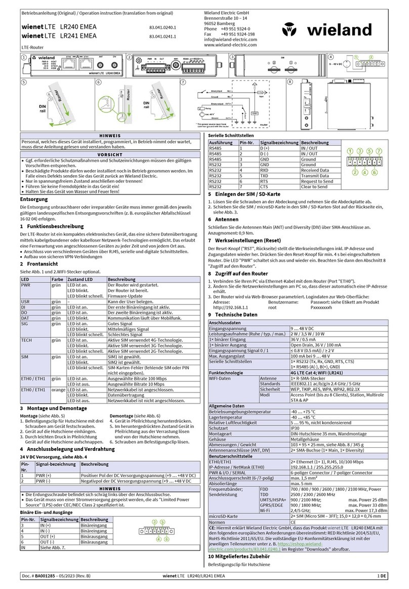
Wieland wienet WR-LTE v3 SL User manual

wienet WR-LTE v3 SL
Industry mobile LTE router
USER MANUAL
Doc.-No. BA001035
Updatet: 08/2016 (Rev. A)

2 Wieland Electric GmbH | BA001035 (Rev. A) | 08/2016
COPYRIGHT
This document is copyright-protected. The rights derived from this cop-
yright are reserved for Wieland Electric GmbH. Reproduction of this
document or parts of this document is only permissible within the lim-
its of the statutory provision of the Copyright Act. Any modification or
abridgment of the document is prohibited without the express written
agreement of Wieland Electric GmbH.
NOTE
Note!
Every effort has been made to ensure that the information contained in
this document was complete and accurate at the time of publishing.
Nevertheless, the authors retain the right to modify the information.
This customer document describes all the hardware units and functions
known at the present time. Descriptions may be included for units
which are not present at the customer site. The exact scope of delivery
is described in the respective purchase contract.
Conformity
Information
For more information regarding CE marking and Declaration of Conformity
(DoC), please contact your local Wieland Electric customer service organi-
zation.
Technical support
Up-to-date information concerning the product is available from the fol-
lowing websites:
http://www.wieland-electric.com/
http://eshop.wieland-electric.com/
Technical support
Industrial Automation -Electronics
Hotline:
+49 951 / 93 24-995
E-Mail:
AT.TS@wieland-electric.com
Adress
Wieland Electric GmbH
Brennerstraße 10-14
96052 Bamberg
Phone: +49 (0) 9 51 93 24-0
Fax: +49 (0) 9 51 93 24-198
E-mail: info@wieland-electric.com
http://eshop.wieland-electric.com
http://www.wieland-electric.com

Contents
Wieland Electric GmbH | BA001035 (Rev. A) | 08/2016 3
1About this manual ........................................................................................ 4
2Product Disposal Instructions ...................................................................... 6
3Router Description ........................................................................................ 7
3.1 Usage of the Router ............................................................................................... 8
4Contents of Package .................................................................................. 10
5Router Design ............................................................................................. 12
5.1 Router versions .................................................................................................... 12
5.2 Delivery identification ........................................................................................... 13
5.3 Ordering codes ..................................................................................................... 13
5.4 Basic dimensions of router box ............................................................................ 13
5.5
Mechanical dimensions and mounting recommendations
.................................... 14
5.6 Removing from the DIN rail ................................................................................. 15
5.7 Description of the rear panel ................................................................................ 16
5.8 Description of the front panel .............................................................................. 16
5.8.1 Status indication ....................................................................................... 17
5.8.2Power connector PWR ............................................................................. 18
5.8.3 Antenna connector ANT, DIV, GPS and WiFi ........................................... 18
5.8.4 SIM card reader ........................................................................................ 19
5.8.5 MicroSD card reader ................................................................................ 19
5.8.6 Ethernet Port (ETH0, ETH1 and ETH2) ..................................................... 20
5.8.7 USB Port ................................................................................................... 20
5.8.8 I/O Port ..................................................................................................... 20
5.8.9 Reset ......................................................................................................... 21
5.9 Interfaces description ........................................................................................... 23
5.9.1 RS232 interface ........................................................................................ 23
5.9.2 RS232-RS485/422 interface ..................................................................... 24
5.9.3 SWITCH interface ..................................................................................... 25
6First Use ..................................................................................................... 26
6.1 Connecting the router before first use ................................................................. 26
6.2 Start ...................................................................................................................... 26
6.3 Configuration ........................................................................................................ 27
6.3.1 Configuration over web browser .............................................................. 27
7Technical Parameters ................................................................................. 30
7.1 Basic parameters .................................................................................................. 30
7.2 Standards and regulations ................................................................................... 30
7.3 Type tests and environmental conditions ............................................................ 31
7.4 Technical parameters of module .......................................................................... 31
7.5 Technical parameters of GPS ............................................................................... 32
7.6 Technical parameters of WiFi ............................................................................... 32
7.7 Technical parameters of I/O port .......................................................................... 32
7.8 Other technical parameters .................................................................................. 32
8Recommended Literature ........................................................................... 34
9Troubleshooting ......................................................................................... 34
10 FAQ ............................................................................................................. 35

About this manual
4 Wieland Electric GmbH | BA001035 (Rev. A) | 08/2016
1About this manual
Please read this section carefully before you use this manual and the
wienet
Router from Wieland. Here you will find
all the information required for commissioning and operation.
1.1 Target groups and qualification of personnel
Commissioning and installation of components for such types of installations must be considered.
Therefore, the system manual is targeted at the following:
•Those who can verify that they have the corresponding training and already have corresponding basic knowledge
•System integrators
•Electricians
1.2 Structure of the manual
As a guidance the overall table of contents is available in the manual at the beginning.
1.3 Presentation of safety-relevant information
Information that warns of personal injury or property damage are emphasized by safety instructions. Please read this
information carefully.
This operating manual uses various safety notices that are assigned according to the severity of a potential hazard:
Danger!
Immediate or likely danger. Personal injury or death is possible.
Warning!
Possible danger. Not heeding this warning can lead to minor injuries.
Attention!
Damages to property is likely if these warnings are not heeded.
Note!
Supplementary information and useful tips, indirectly related to the safety of personnel or property.
"Danger" or "Warning" are strictly used for cases which present a risk to life or limb. Damage to property only
falls into these categories if there is also a risk of personal injury that corresponds to these levels.
DANGER
WARNING
ATTENTION
NOTE

Contents
Wieland Electric GmbH | BA001035 (Rev. A) | 08/2016 5
Please, observe the following instructions:
Attention!
•The router must be used in compliance with all applicable international and national laws and
in compliance with any special restrictions regulating the utilization of the router in prescribed
applications and environments.
•To prevent possible injury to health and damage to appliances and to ensure that all the rele-
vant provisions have been complied with, use only the original accessories.
•Unauthorised modifications or utilization of accessories that have not been approved may re-
sult in damage to the router and in a breach of applicable regulations. Unauthorized modifica-
tions or utilization of accessories that have not been approved may result in the termination of
the validity of the guarantee.
•The router can not be opened.
•Before handling of the SIM card turn off the router and disconnect it from power supply.
Attention!
•Caution! The SIM card could be swallowed by small children.
•It must not be exceeded by the maximum voltage 60 V DC power connector on the router.
•Do not expose the router to extreme ambient conditions. Protect the router against dust, mois-
ture and high temperature.
•The router should not be used at petrol stations of flammable and explosive materials. We re-
mind the users of the duty to observe the restrictions concerning the utilization of radio de-
vices at petrol stations, in chemical plants, or in the course of blasting works in which explo-
sives are used.
•Switch off the router when travelling by plane. Utilization of the router in a plane may endan-
ger the operation of the plane or interfere with the mobile telephone network, and may be un-
lawful. Failure to observe these instructions may result in the suspension or cancellation of
telephone services for the respective client, or, it may result in legal sanctions; it may also re-
sult in both eventualities.
•When using the router in the close proximity of personal medical devices, such as cardiac
pacemakers or hearing aids, you must proceed with heightened caution.
•If it is in the proximity of TV sets, radio receivers and personal computers, the telephone may
cause interference.
•It is recommended that you should create an appropriate copy or backup of all the important
•settings that are stored in the memory of the device.
ATTENTION
WARNING

2| Product Disposal Instructions
6 Wieland Electric GmbH | BA001035 (Rev. A) | 08/2016
2Product Disposal Instructions
The WEEE (Waste Electrical and Electronic Equipment: 2002/96/EC) directive has been introduced to en-
sure that electrical/electronic products are recycled using the best available recovery techniques to mini-
mize the impact on the environment. This product contains high quality materials and components which
can be recycled. At the end of it’s life this product MUST NOT be mixed with other commercial waste for
disposal. Check the terms and conditions of your supplier for disposal information.

3 | Router Description
Wieland Electric GmbH | BA001035 (Rev. A) | 08/2016 7
3Router Description
Cellular router
wienet
WR-LTE v3 SL is designed for wireless communication in mobile networks that
make use of LTE, HSPA+, UMTS, EDGE or GPRS technology. Due to the high speed of data transfer up
to 100 Mbit/s (download) and up to 50 Mbit/s (upload) is this router an ideal solution for wireless connec-
tion of traffic and security camera systems, remote machines, individual computers, LAN networks, auto-
matic teller machines (ATM) and other self-service terminals.
As a standard, cellular router is equipped with two Ethernet 10/100, one USB 2.0 Host port, two binary
inputs and one output (I/O connector). The device also has two readers for 3 V and 1.8 V SIM cards,
which are placed on the rear panel of the router. An integral part of the router is also a memory card
reader. This reader allows
wienet
WR-LTE v3 SL to operate with microSD cards and increase storage
space of the router up to 64 GB (32 GB in case of SDHC cards). The router can be equipped with WiFi
module on customer’s request, however it is not possible to add it to the router at some time in the fu-
ture. Richer range of interfaces is available in versions containing one of these ports: SWITCH, RS232 or
RS485/RS232. These are three switched Ethernets, serial interface RS232 and combination of serial inter-
face RS485 and RS232.
wienet
WR-LTE v3 SL is supplied in a metal casing, based on the requirements of
the customer.
For configuration of the cellular router a web interface is available protected by password. Web interface
provides (after logging in) detailed statistics about the router activities, signal strength, detailed system
log etc. This device supports the creation of VPN tunnels using technologies IPSec, OpenVPN and L2TP
for secure communications. There are also supported functions such as DHCP, NAT, NAT-T, DynDNS,
NTP, VRRP, control by SMS, backup primary connection and many other functions.
Other diagnostic functions ensuring continuous communication include automatic inspection of PPP con-
nection offering an automatic restart feature – in case of connection losses, or hardware watchdog which
monitors the status of the router. With the help of a special window (start up script window) you may in-
sert Linux scripts for various actions. For some applications the key option to create several different con-
figurations for one LTE wireless router and the option to switch between them (for example via SMS, bi-
nary input status, etc.) is essential. Cellular wireless routers
wienet
WR-LTE v3 SL may automatically up-
grade configuration and firmware from server. This allows mass reconfiguration of many routers in one
time.
Examples of possible applications
•remote service for machines
•mobile office
•fleet management
•security system
•telematic
•telemetric
•remote monitoring
•vending and dispatcher machines

3| Router Description
8 Wieland Electric GmbH | BA001035 (Rev. A) | 08/2016
3.1 Usage of the Router
The router is primarily intended for these four basic situations:
I. Access to the Internet from LAN
II. Backed up access to the Internet (from LAN)

3 | Router Description
Wieland Electric GmbH | BA001035 (Rev. A) | 08/2016 9
III. Secure networks interconnection or using VPN)
IV. Serial Gateway

4| Contents of Package
10 Wieland Electric GmbH | BA001035 (Rev. A) | 08/2016
4Contents of Package
Basic delivered set of router includes:
•router,
•power connector cable
•crossover UTP cable,
•up to three external antennas,
•loose power and I/O connector
•clip for the DIN rail,
•installation instructions.
•USB-Stick with documentation


5| Router Design
12 Wieland Electric GmbH | BA001035 (Rev. A) | 08/2016
5Router Design
5.1 Router versions
The
wienet
WR-LTE v3 SL router is supplied in the following versions (see table below). All versions are
available in metal box according to customer requirements.
Router versions
SIM
BIN
BOUT
USB
SD
ETH
WiFi
232
485
Basic version
2 x
2 x
1 x
1 x
1 x
2 x
Basic version with WiFi
2 x
2 x
1 x
1 x
1 x
2 x
1 x
Version with SWITCH board
2 x
2 x
1 x
1 x
1 x
5 x
Version with SWITCH board & WiFi
2 x
2 x
1 x
1 x
1 x
5 x
1 x
Version with RS232 board
2 x
2 x
1 x
1 x
1 x
2 x
1 x
Version with RS485/232 board
2 x
2 x
1 x
1 x
1 x
2 x
1 x
1 x
Version with RS232/485 & WiFi
2 x
2 x
1 x
1 x
1 x
2 x
1 x
1 x
1 x
Basic version
Version with SWITCH interface
Version with RS485/232 interface
Version with RS232 interface
Basic version with WiFi
Version with SWITCH interface and WiFi
Version with RS485/232 and WiFi

5 | Router Design
Wieland Electric GmbH | BA001035 (Rev. A) | 08/2016 13
5.2 Delivery identification
Trade name
wienet
Type name
WR-LTE-v3-SL
Other
Router in metal box
5.3 Ordering codes
Ordering codes overview is shown in the table below.
Name
Order code
Features – interfaces
WR-LTE v3 SL
83.041.0700.1
2x ETH, USB, 2DI, 1DO, 2xSIM
WR-LTE v3 SL WIFI
83.041.0760.1
2x ETH, USB, 2DI, 1DO, 2xSIM, WIFI
WR-LTE v3 SL RS232
83.041.0701.1
2x ETH, USB, 2DI, 1DO, 2xSIM,
RS232
WR-LTE v3 SL RS232+RS422/485
83.041.0702.1
2x ETH, USB, 2DI, 1DO, 2xSIM,
RS232+RS422/485
WR-LTE v3 SL RS232+RS422/485 WIFI
83.041.0762.1
5.3.1.1 2x ETH, USB, 2DI, 1DO,
2xSIM, RS232+RS422/485,
WIFI
WR-LTE v3 SL 5-Port
83.041.0709.1
5x ETH, USB, 2DI, 1DO, 2xSIM
WR-LTE v3 SL 5-Port WIFI
83.041.0769.1
5x ETH, USB, 2DI, 1DO, 2xSIM, WIFI
5.4 Basic dimensions of router box

5| Router Design
14 Wieland Electric GmbH | BA001035 (Rev. A) | 08/2016
5.5 Mechanical dimensions and mounting recommenda-
tions
Possibility to be put on a work surface,
DIN rail EN 60715 with included clip.
For the most of applications with a built-in router in a switch board it is possible to recognize
two kinds of environments:
1. no public and industry environment of low voltage with high interference,
2. public environment of low voltage without high interference.
For both of these environments it is possible to mount the router to a switch board if the common EMC-
rules according to EN 60439-1 are noted.
Note!
Compliance of EN 60439-1 ed.2:00 + A1:04 specification it is necessary to observe next as-
sembly of the router to the switch – board.
For several cables we recommend to bind the bunch. We recommend for this use:
–The Length of the bunch (combination of power supply and data cables) can be a maximum of
1.5 m. If the length of data cables exceeds 1.5 m or if the cables are lead outside the switch –
board, we recommend installing over – voltage protectors (surge suppressors).
–Between data cables and cables with reticular tension of ~ 230 V / 50 Hz sufficient space (min.
50 mm) should be kept.
–A certain space must be kept before the cables for connecting or disconnecting singular cables.
For correct function of the router we recommend to use it in a switch-board with earth-bonding distribu-
tion frame for grounding of the power supply, of the router, the data cables and the antenna.
NOTE

5 | Router Design
Wieland Electric GmbH | BA001035 (Rev. A) | 08/2016 15
5.6 Removing from the DIN rail
The DIN holder is suitable for DIN rail according to EN 60715. The default position of the holder for the
metal version is used for mounting the router on a DIN rail, which is shown in the following figure:
Default position of DIN holder
For removing from the DIN rail:
1. lightly push the router upward
2. fold out the top part of the router away from the DIN rail.
Removing from the DIN rail

5| Router Design
16 Wieland Electric GmbH | BA001035 (Rev. A) | 08/2016
5.7 Description of the rear panel
The rear panel contains only two holders for SIM cards (SIM1 and SIM2), holder for SD card (SD)
and RST button used to restore default configuration and reboot the router.
5.8 Description of the front panel
The front panel contains the following connectors:
Caption
Connector
Description
PWR
2-pin
Connector for the power supply
ETH0
RJ45
Connector for connection into the computer network
ETH1
RJ45
Connector for connection into the computer network
ETH2
RJ45
3x Connector for connection into the computer network (only for 5-Port
version)
ANT
SMA
Connector for main antenna
DIV
SMA
Connector for diversity antenna
GPS
SMA
Connector for GPS antenna
WiFi
R-SMA
Connector for WiFi antenna (only for versions with WiFi module!)
USB
USB-A 2.0
Host
Connector for connection of USB devices to the router. Supports
devices with PL-2303 and FTDI USB/RS232 converters.
I/O
6-pin
Connector for connection of the binary inputs and output
wienet
WR-LTE v3 SL front panel

5 | Router Design
Wieland Electric GmbH | BA001035 (Rev. A) | 08/2016 17
5.8.1 Status indication
Router status is shown by nine LED indicators on the front panel. Each ETH port has two additional
LEDs that provide information about theport status.
Caption
Color
State
Description
PWR
Green
Blinking
On
Fast blinking
Router is ready
Starting of the router
Updating firmware
USR
Yellow
—
Function of this LED diode can be selected by user
POE
Yellow
Green
—
—
SIM
Yellow
Green
On (Yellow color)
On (Green color)
The first SIM card is active
The second SIM card is active
WAN
Yellow
1x flash per sec.
2x flash per sec.
3x flash per sec.
Signal strength is from –50 dBm to –69 dBm
Signal strength is from –70 dBm to –89 dBm or difference
between neighbours cells is exactly 3 dBm
Signal strength is from –90 dBm to –113 dBm or differ-
ence between neighbours cells is smaller than 3 dBm
DAT
Red
Blinking
Communication in progress on radio channel
IN0
Green
On
Binary input no. 0 is active
IN1
Green
On
Binary input no. 1 is active
OUT
Yellow
On
Binary output is active
ETH0
ETH1
ETH2
Green
On
Off
Selected 100 Mbit/s
Selected 10 Mbit/s
ETH0
ETH1
ETH2
Yellow
On
Blinking
Off
The network cable is connected
Data transmission
The network cable is not connected
Attention!
State indication of WAN LED is updated every 10 seconds.
ATTENTION

5| Router Design
18 Wieland Electric GmbH | BA001035 (Rev. A) | 08/2016
5.8.2 Power connector PWR
Panel socket 2-pin.
Pin number
Signal mark
Description
1
GND(-)
Negative pole of DC supply voltage
2
VCC(+)
Positive pole of DC supply voltage (+10 to +60 V DC)
Power connector
Power supply for the router must be between +10 V to +60 V DC supply. Protection against reversed po-
larity without signaling is built into the router.
wienet
WR-LTE v3 SL can be put into "low power mode" using a special command. Then it can be awak-
ened for example by an activity on the binary input or using an internal timer.
Circuit example:
Connection of power supply
5.8.3 Antenna connector ANT, DIV, GPS and WiFi
Main, diversity and GPS antennas are connected to the router using the SMA connector on the front
panel. There is also available R-SMA antenna connector through which the additional antenna can be
connected, if the router is equipped with WiFi module.
ANT connector is used to connect the main antenna router. To connect the diversity antenna is used the
second antenna connector DIV. The third connector (GPS) is intended for GPS antenna (router supports
active GPS antenna). R-SMA connector named WiFi is designed for connection of WiFi antenna (available
only for versions with WiFi module).
Attention!
The router can not operate without a connected main antenna marked as ANT!
For connection the antenna is used SMA con-
nector. The antenna is connected by screwing
this antenn to the SMA connector on the front
panel of the router (see figure below).
NOTICE
: Diversity antenna improves radio fea-
tures of the router at low signal strength
Diversity antenna improves radio features of the router at low signal strength.
ATTENTION

5 | Router Design
Wieland Electric GmbH | BA001035 (Rev. A) | 08/2016 19
5.8.4 SIM card reader
Two SIM card readers for 3 V and 1.8 V SIM cards are placed on the rear panel of the router. For getting
the router to work it is necessary to insert an activated SIM card with an unblocked PIN code.
The SIM cards might be of different adjusted APN (Access Point Name).
Changing the SIM card:
•Before handling of the SIM card disconnect the router from power supply!
•Use a plastic opening tool, or your fingernail, to press the SIM card slightly deeper into its slot until you
hear a click.
•After the click, release the card and it will pop out of its slot.
•Remove the SIM card and push any other SIM card into the slot until it clicks in place.
5.8.5 MicroSD card reader
The microSD card reader is placed on the rear panel of the router (the third slot). This card reader allows
the router to operate with microSD memory cards. Technical specifications are stated in the table below:
Technical specifications of microSD card
Supported technologies
SDHC, SDXC
Supported capacity
SDHC
SDXC
up to 32 GB
from 32 GB to 64 GB
Changing the microSD card:
•Use the flat end of a spudger, or your fingernail, to press the microSD card slightly deeper into its slot
until you hear a click.
•After the click, release the card and it will pop out of its slot.
•Remove the microSD card and push any other microSD card into the slot until it clicks in place.
SD card

5| Router Design
20 Wieland Electric GmbH | BA001035 (Rev. A) | 08/2016
5.8.6 Ethernet Port (ETH0, ETH1 and ETH2)
Panel socket RJ45.
Pin
Signal
mark
Description
Data flow direction
1
TXD+
Transmit Data – positive pole
Input/Output
2
TXD-
Transmit Data – negative pole
Input/Output
3
RXD+
Receive Data – positive pole
Input/Output
4
DC+
POE power + (if POE is
equipped)
5
DC+
POE power + (if POE is
equipped)
6
RXD-
Receive Data – negative pole
Input/Output
7
DC-
POE power - (if POE is equipped)
8
DC-
POE power - (if POE is equipped)
Ethernet connector
Connection of Ethernet connector
Plugging of ethernet cable into the RJ45 con-
nector(labeled as ETH0 or ETH1).
5.8.7 USB Port
Panel socket USB-A.
Pin
Signal mark
Description
Data flow direction
1
+5 V
Positive pole of 5 V DC supply voltage, 0.5 A
2
USB data -
USB data signal – negative pole
Input/Output
3
USB data +
USB data signal – positive pole
Input/Output
4
GND
Negative pole of DC supply voltage
Connection of USB connector
USB connector
5.8.8 I/O Port
Panel socket 6-pin.
Pin
Signal mark
Description
1
IN0
Binary input 0
2
IN0
Binary input 0
3
IN1
Binary input 1
4
IN1
Binary input 1
5
OUT
Binary output
6
OUT
Binary output
I/O connector
Note!
The insulation strength is up to 1.5 kV.
NOTE
Other manuals for wienet WR-LTE v3 SL
1
Table of contents
Other Wieland Wireless Router manuals
