Wieland wienet LTE LR240 User manual

Manual
Doc. No. BA001291
Last Update: 07/2022 (Rev. A)
wienet LTE
LR240/241
Industrial
mobile LTE router

Info
Wieland Electric
GmbH | BA001291 | 07/2022 (Rev. A)
2
INFO
This document is copyright-protected. The rights derived from this copyright are reserved for
Wieland Electric. Reproduction of this document or parts of this document is only permissible within
the limits of the statutory provision of the Copyright Act. Any modification or abridgment of the
document is prohibited without the express written agreement of Wieland Electric.
wienet LTE is a trademark of Wieland Electric. Other product or brand names mentioned in this
document are brand trademarks or registered trademarks of their respective owners. Usage of these
names and trademarks by third parties for their own purposes could violate the rights of the owners.

Table of Contents
Wieland Electric
GmbH | BA001291 | 07/2022 (Rev. A)
3
TABLE OF CONTENTS
1About this Manual 5
1.1 Function of the manual 5
1.2 Other applicable documents 5
1.3 Target group 5
1.4 Symbols and notations 6
2Safety 7
2.1 Hazardous locations installation instructions 7
2.2 General safety instructions 7
3Product Overview 9
3.1 Product Introduction 9
3.2 Router Versions 9
3.3 Delivery Identification 10
3.4 Product Label 10
3.5 Order Codes 10
3.6 Hardware Overview 11
3.7 Package Contents 12
3.8 Product Dimensions 13
4Product Usage Examples 14
4.1 Access to the Internet from LAN 14
4.2 Backed up access to the Internet (from LAN) 14
4.3 Secure networks interconnection or using VPN 15
4.4 Serial Gateway 15
5Mounting and Removal 16
5.1 Mounting Recommendations 16
5.2 DIN Rail Mounting 16
5.3 Removing from the DIN rail 17

Table of Contents
Wieland Electric
GmbH | BA001291 | 07/2022 (Rev. A)
4
6Hardware Functionality 18
6.1 SIM Card Slots 18
6.2 Cellular Antennas 18
6.3 Ethernet Interfaces 19
6.4 Power Supply 20
6.5 I/O Port Interfaces 21
6.6 Serial Interfaces 22
6.7 LED Status Indication 23
6.8 Reset Functions 24
7First Use 25
7.1 Powering up the Router 25
7.2 Router Configuration 25
8Technical Specifications 27
8.1 Basic Parameters 27
8.2 Standards and Regulations 27
8.3 Type Tests and Environmental Conditions 28
8.4 Parameters of Cellular Module 28
8.5 Parameters of I/O Ports 29
8.6 System Configuration 29
9Troubleshooting 30
10 Disposal 32
11 Service and Support 33

About this Manual
Wieland Electric
GmbH | BA001291 | 07/2022 (Rev. A)
5
1ABOUT THIS MANUAL
Please read this chapter carefully before using the user manual or the products.
1.1 Function of the manual
This user manual provides technical staff with information about the device and its functions. This
manual contains the necessary information for the intended use and the technical data of the
projects described in it. As a guidance the overall table of contents is available in the manual at the
beginning.
Use the manual BA001038 for the configuration of wienet LTE v2/v3 Router, see Table 1.
1.2 Other applicable documents
You can also use our website https://eshop.wieland-electric.com.
Following files downloadable:
•Product information wienet router
•Data sheets wienet router
•Technical notes wienet Wie-Service24 VPN Server
Table 1: Other applicable documents
Document Title Article number
Installation instructions
Installation instructions
wienet LTE LR240/241
BA001285
Configuration manual
wienet
LTE v2/v3 Router
Configuration
BA001038
1.3 Target group
This manual is intended for:
•Those who can prove that they have the corresponding training and already have
corresponding basic knowledge of commissioning electrical installations.
•System integrators
•Electricians
•Electrical system operator
NOTE

About this Manual
Wieland Electric
GmbH | BA001291 | 07/2022 (Rev. A)
6
1.4 Symbols and notations
The symbol 'DANGER' means an imminent danger. If it is not avoided, it can result in death or
serious injury.
'DANGER' is used to warn of dangers at the time of the warning are already existing (e.g., hot
surfaces, sharp edges, pinch points, etc.).
It is used exclusively in danger of personal injury!
The symbol 'WARNING' indicates a possible threat. If it is not avoided, it can result in death or
serious injury could result.
The symbol 'CAUTION' indicates a possible threat. If it is not avoided, slight or minor injury can
result.
Refer to notes for special features of a device.
Instructions also tell you about a potentially harmful situation. If it is not avoided, the system can be
damaged or something in their environment.
DANGER
WARNING
CAUTION
NOTE

Safety
Wieland Electric
GmbH | BA001291 | 07/2022 (Rev. A)
7
2SAFETY
2.1 Hazardous locations installation instructions
These devices are open-type devices that are to be installed in an enclosure suitable for the
environment and can only be accessed with the use of a tool or key.
This equipment is suitable for use in Class I, Division 2, Groups A, B, C, and D or nonhazardous
locations only. This equipment shall be mounted in an ATEX Zone 2 certified enclosure with a
minimum ingress protection rating of at least IP54 (as defined in EN 60529) and used in an
environment of not more than Pollution Degree 2 (as defined in EN 60664-1) when applied in Zone 2
environments. The enclosure must be accessible only by the use of a tool.
Explosion hazard
•Do not disconnect equipment unless the power has been removed or the area is known to be non-
hazardous.
•Substitution of any components may impair suitability for class I, division 2.
•Batteries must only be changed in an area free of ignitable concentration.
All antennas, antenna cables and wiring have not been evaluated as external wiring.
Provision shall be made to prevent the rated voltage from being exceeded by transient disturbances
of more than 140 % of the rated voltage when applies in Zone 2 environments.
2.2 General safety instructions
Safety Notices
Please, observe the following instructions.
•The router must be used in compliance with all applicable international and national laws and in
compliance with any special restrictions regulating the utilization of the router in prescribed
applications and environments.
•To prevent possible injury and damage to appliances and to ensure compliance with all relevant
provisions, use only the original accessories. Unauthorized modifications or the use of
unapproved accessories may result in damage to the router and / or a breach of applicable
regulations. Unauthorized modifications or use of unapproved accessories may void the warranty.
•The router cannot be opened.
•Turn off the router and disconnect it from power supply before handling the SIM card.
•Input voltage must not exceed 48 V DC.
This equipment is not suitable for use in locations where children are likely to be present. The SIM
card could be swallowed by small children.
WARNING
CAUTION
DANGER

Safety
Wieland Electric
GmbH | BA001291 | 07/2022 (Rev. A)
8
•Do not expose the router to extreme ambient conditions. Protect the router against dust,
moisture and high temperature.
•Only routers with appropriate certification and labelling should be used in locations where
flammable and explosive materials are present, including gas stations, chemical plants, or
locations in which explosives are used. We remind users of the duty to observe the restrictions
concerning the utilization of radio devices at such places.
•Switch off the router when travelling by plane. Utilization of the router on a plane may endanger
the operation of the plane or interfere with the mobile telephone network, and may be
unlawful. Failure to observe these instructions may result in the suspension or cancellation of
telephone services for the respective client and / or may result in legal sanctions.
•When using the router in close proximity to personal medical devices, such as cardiac
pacemakers or hearing aids, you must proceed with heightened caution.
•The router may cause interference when used in close proximity to TV sets, radio receivers or
personal computers.
•It is recommended that you create an appropriate copy or backup of all important settings that
are stored in the memory of the device.

Product Overview
Wieland Electric
GmbH | BA001291 | 07/2022 (Rev. A)
9
3PRODUCT OVERVIEW
3.1 Product Introduction
Industrial cellular router wienet LTE LR240/241 is designed for wireless communication in mobile
networks that make use of traditional cellular technologies. It can also be used as a simple LAN-to-
LAN router.
The primary purpose of this router is its use in the Category 4 (Cat.4) services on the cellular LTE
network. Cat.4 rated router is capable of achieving typical speeds in 4G coverage areas where the
network is enabled with 20 MHz of contiguous spectrum.
The peak downlink data rate for Category 4 is approximately 150 Mbps. In the uplink, LTE Category
4 provides a peak data rate of 50 Mbps. The router is equipped with two independently configurable
Ethernet ports, RS232 and RS485 serial ports and with one digital input together with one digital
output.
The router supports VPN tunnel creation using various protocols to ensure safe communications.
The router provides diagnostic functions which include automatic monitoring of the wireless and
wired connections, automatic restart in case of connection losses, and a hardware watchdog that
monitors the router status.
With open Linux platform and wide possibilities of programming customer SW applications in
Python, C/C++.
Examples of possible applications:
•Mobile office
•Security system
•Telematic
•Remote monitoring
•Vending and dispatcher machines
3.2 Router Versions
The wienet LTE LR240/241 router is supplied in the following versions, see Table 2. All versions are
available in metal box according to customer requirements.
Table 2: Router versions
Type SIM BIN BOUT ETH Wi-Fi
LR240
2 ×
1 ×
1 ×
2 ×
LR241
2 ×
1 ×
1 ×
2 ×
1 ×
Figure 1: Version LR240

Product Overview
Wieland Electric
GmbH | BA001291 | 07/2022 (Rev. A)
10
3.3 Delivery Identification
Table 3: Delivery Identification
Trade name
wienet
Type name
LTE LR240/241
Other
Router in metal box
3.4 Product Label
An example of the product label, with all the information printed on it, is in Figure 2.
Figure 2: Label Example
3.5 Order Codes
Order codes overview is shown in Table 4.
Table 4: Order Codes Overview
Product
name
Order code Features – interfaces
LTE LR240
83.041.0240.1
2× ETH, 1Di, 1DO, 2× SIM, 1× RS232, 1× RS485
LTE LR241
83.041.0241.1
2× ETH, 1Di, 1DO, 2× SIM, 1× RS232, 1× RS485, WLAN

Product Overview
Wieland Electric
GmbH | BA001291 | 07/2022 (Rev. A)
11
3.6 Hardware Overview
The router case preview is shown in Figure 3 and Figure 4. A short description of hardware parts of
the router is listed in Table 5, including the links to the chapters with a detailed description.
Figure 3: Front view
Figure 4: Rear view

Product Overview
Wieland Electric
GmbH | BA001291 | 07/2022 (Rev. A)
12
Table 5: Hardware Overview of the Router
# Item/Caption Type Description
1
Grounding
screw
M3
Pay attention to proper grounding, see chapter 6.4 "Power
Supply", p.20.
2
PWR
6-pin
terminal
Power supply socket, see chapter 6.4 "Power Supply", p. 20.
IN/OUT
6-pin
terminal
Binary input & output interfaces, see chapter 6.5 "I/O Port
Interfaces", p.21.
3
RS485/RS232
7-pin
terminal
RS232 & RS485 serial interfaces, see chapter 6.6 "Serial
Interfaces", p.22.
4
LEDs
-
Status LED indication, see chapter 6.7 "LED Status Indication",
p.23.
5
RST
-
Button to reboot the router or to restore the default
configuration, see chapter 6.8 "Reset Functions", p.24.
6
ETH0
RJ45
100 MB Ethernet connection for the first LAN, see chapter 6.3
"Ethernet Interfaces", p.19.
ETH1
RJ45
100 MB Ethernet connection for the second LAN, see chapter 6.3
"Ethernet Interfaces", p. 19.
7
ANT
SMA
Connector for the first main antenna of the cellular module, see
chapter 6.2 "Cellular Antennas", p. 18.
8
DIV
SMA
Connector for the first diversity antenna of the cellular module,
see chapter 6.2 "Cellular Antennas", p. 18.
9
SIM slots
micro-SIM
Two SIM card slots, see chapter 6.2 "Cellular Antennas", p.18.
10
DIN clip
-
DIN rail clip, see chapter 5.2 "DIN Rail Mounting", p.16.
11
Wall clip
-
Wall mounting clip, included as standard accessories.
3.7 Package Contents
The standard set of router includes items listed in Table 6.
Table 6: Package Contents
Item#
Description Figure Q'ty
1
Router
1 pcs
2
DIN rail clip
1 pcs
Product Overview
Wieland Electric
GmbH | BA001291 | 07/2022 (Rev. A)
13
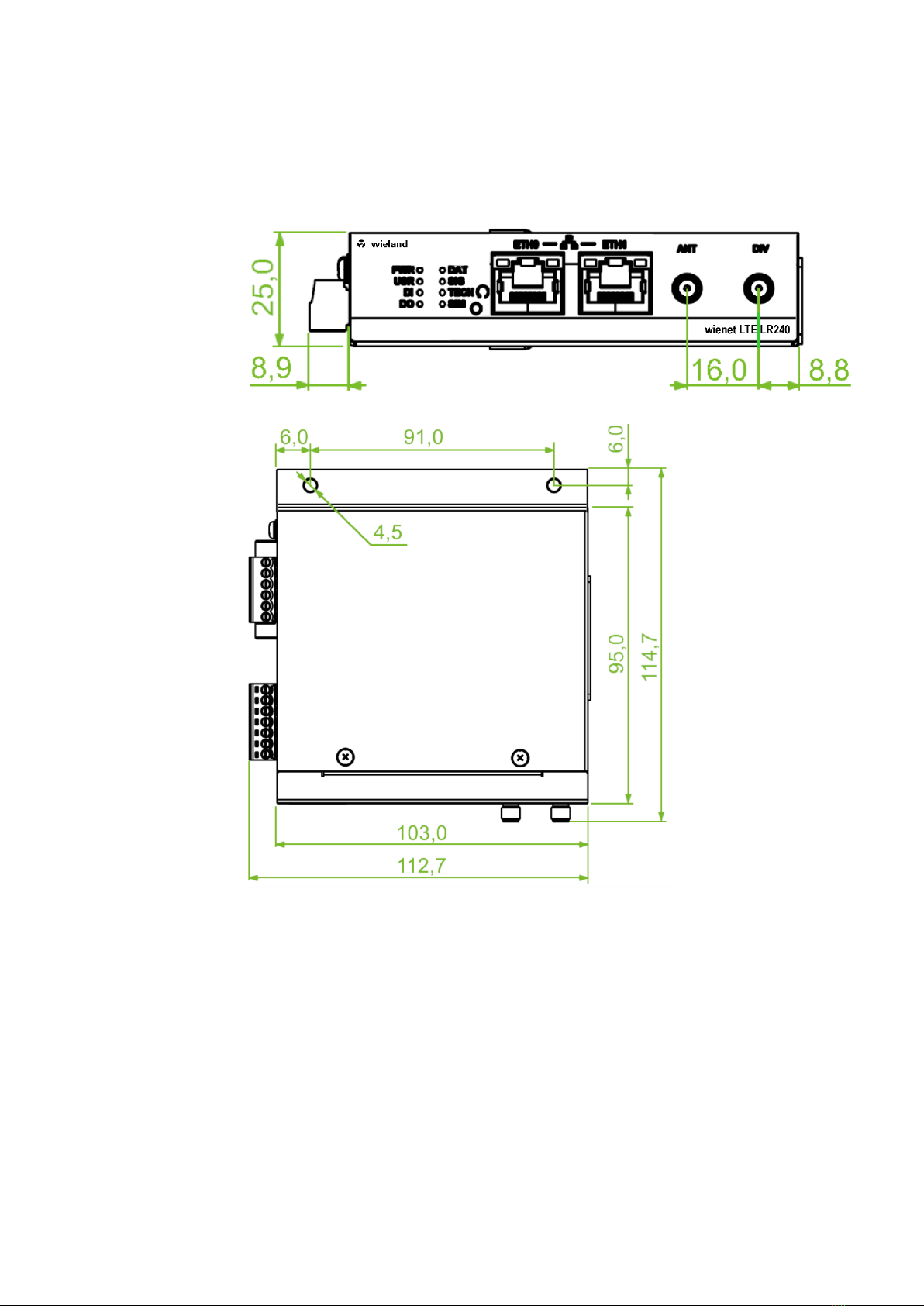
3.8 Product Dimensions
For the dimensions of the product see Figure 5 and Figure 6. Note that all sizes are measured in
millimeters.
Figure 5: Product Dimensions – Front View
Figure 6: Product Dimensions (with wall mounting clip) – Top View

Product Usage Examples
Wieland Electric
GmbH | BA001291 | 07/2022 (Rev. A)
14
4PRODUCT USAGE EXAMPLES
The router is primarily intended for these four basic situations.
4.1 Access to the Internet from LAN
Figure 7: Access to the Internet from LAN
4.2 Backed up access to the Internet (from LAN)
Figure 8: Backed up access to the Internet

Product Usage Examples
Wieland Electric
GmbH | BA001291 | 07/2022 (Rev. A)
15
4.3 Secure networks interconnection or using VPN
Figure 9: Using VPN Tunnel
4.4 Serial Gateway
Figure 10: Serial Gateway

Mounting and Removal
Wieland Electric
GmbH | BA001291 | 07/2022 (Rev. A)
16
5MOUNTING AND REMOVAL
5.1 Mounting Recommendations
The router can be placed:
•on a flat surface,
•on a DIN rail EN 60715 with the metal DIN rail clip. See chapter 5.2 "DIN Rail Mounting", p.16.
For most applications with a built-in router within a switchboard, it is possible to recognize two
kinds of environments:
•a non-public, industry environment of low voltage with high interference,
•a public environment of low voltage and without high interference.
For both of these environments, it is possible to mount the router to a switchboard, after which
there is no need to have examination immunity or issues in connection with EMC according to
EN 61439-1:2011.
In compliance with the EN 61439-1:2011 specification, it is necessary to observe the following
assembly instructions for a router attached to a switchboard:
•For whip antennas it is recommended to observe a minimum distance of 6 cm from cables and
metal surfaces on every side in order to avoid interference. When using an external antenna
separate from the switchboard it is necessary to fit a lightning conductor.
•When mounting a router on sheet-steel we recommend using a cable antenna.
•For all cables, we recommend to bind the bunch, and for this we recommend:
– The length of the bunch (the combination of power supply and data cables) should be a
maximum 1.5 m. If the length of data cables exceeds 1.5 m or if the cable is leading towards the
switchboard, we recommend installing surge protectors.
– Data cables must not have a reticular tension of ~ 230 V/50 Hz or ~ 120 V/60 Hz.
•Sufficient space must be left between each connector for the handling of cables.
•To ensure the correct functioning of the router we recommend the use of an earth bonding
distribution frame for the grounding of the grounding screw, see chapter 6.4 "Power Supply",
p.20.
5.2 DIN Rail Mounting
The DIN rail clip is supplied with the router as standard accessories.
The DIN rail clip is suitable for a DIN rail according to EN 60715 standard only. The default position of
the clip is shown in Figure 11.
When mounting the wall mounting clip, tighten the screws with max. torque of 0.4 Nm.
Figure 11: Position of the DIN Rail Clip
CAUTION
NOTE
CAUTION

Mounting and Removal
Wieland Electric
GmbH | BA001291 | 07/2022 (Rev. A)
17
5.3 Removing from the DIN rail
Push the router down lightly, so the bottom part of the DIN rail clip (hitched to the DIN rail) gets
out of the rail.
Pull out the bottom part of the router away from the DIN rail.
Figure 12: Removing Router from the DIN Rail

Hardware Functionality
Wieland Electric
GmbH | BA001291 | 07/2022 (Rev. A)
18
6HARDWARE FUNCTIONALITY
See chapter 3.6 "Hardware Overview", p. 11 for the product hardware overview. Table 5lists a short
description of the hardware, including the links to the chapters with a detailed description.
6.1 SIM Card Slots
Slots for two SIM cards are located on the right panel of the router under a metal cover. It is
necessary to insert an activated SIM card, to work properly. If the PIN is required for the SIM, enter it
in the router's web interface. The SIM cards may have different APNs (Access Point Names) adjusted.
The SIM card changing procedure is described below.
Type of SIM cards: micro-SIM (3FF) 15.0 × 12.0 × 0.76 mm.
Inserting the SIM card:
•Always disconnect the router from the power supply before handling the SIM card.
•Unscrew two screws on the SIM card cover and remove the cover.
•To remove an inserted SIM card, use the flat end of a spudger, or your fingernail, press the SIM
card slightly into its slot until you hear a click. After hearing this click, release the card, and it will
pop out of its slot.
•To insert a SIM card, push card into the slot until it clicks into place.
•Place back the cover and fix it by two screws.
Figure 13: SIM Cards Insertion
6.2 Cellular Antennas
Main (ANT) and diversity (DIV) antennas can be connected to the router using the SMA connectors
located on the front panel.
Do not run the router without connected cellular antenna connected to the main antenna
connectors as the energy from the transmission is effectively reflected by the open end and can
damage the equipment.
•Recommended tightening moment for screwing the antenna to the SMA connector is 0.9 Nm.
•The diversity antenna improves the radio capability of the router at low signal strength.
NOTE
CAUTION
CAUTION
NOTE

Hardware Functionality
Wieland Electric
GmbH | BA001291 | 07/2022 (Rev. A)
19
6.3 Ethernet Interfaces
The panel socket of RJ45 is used for Ethernet interface. The pinout of the socket is shown in
Figure 14 and described in Table 7.
Figure 14: Ethernet Connector Pinout
Table 7: Ethernet Connector Pinout Description
Pin Signal mark Description
1
TXD+
Transmit Data – positive pole
2
TXD-
Transmit Data – negative pole
3
RXD+
Receive Data – positive pole
4
—
—
5
—
—
6
RXD-
Receive Data – negative pole
7
—
—
8
—
—
The isolation barrier of the Ethernet ports against the ground is 1500 V.
NOTE

Hardware Functionality
Wieland Electric
GmbH | BA001291 | 07/2022 (Rev. A)
20
6.4 Power Supply
The pins of power supply are physically connected to the 6-pin terminal block panel socket located
on the left panel. The connection of power supply is shown in Figure 15 and described in Table 8.
Figure 15: Connection of Power Supply
Table 8: Power Supply Pinout
Pin Signal mark Description
1
PWR(+)
Positive pole of DC supply voltage (+9 … +48 V DC)
2
PWR(-)
Negative pole of DC supply voltage
Required power supply voltage for the router is between +9 V and +48 V DC, see the connection
scheme on Figure 15. Protection against reversed polarity without signaling is built into the router.
For correct operation it is necessary that the power source is able to supply a peak current of 1 A.
Unit has to be supplied by a power supply specified as a Limited Power Source (LPS) or CEC/NEC
Class 2 source of supply.
The metal case of the router is not connected to the negative pole of the power supply (common
pole). If recommended for the installation environment, protect the router by grounding it properly
by the grounding screw on the right panel, see Figure 16.
Figure 16: Position of the Grounding Screw
CAUTION
Other manuals for wienet LTE LR240
1
This manual suits for next models
1
Table of contents
Other Wieland Wireless Router manuals


