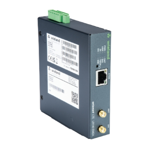
Wieland wienet LTE v3 SL User manual

Montageanleitung (Original)
wienet WR-LTE v3 SL 83.041.07xx.1
LTE-Router
Wieland Electric GmbH
Brennerstraße 10
– 14
96052 Bamberg
Phone
+49 951 9324-0
Fax
+49 951 9324-198
info@wieland
-electric.com
www.wieland-electric.com
Doc. # BA000774 – 11/2020 (Rev. D) wienet WR-LTE v3 SL DE
HINWEIS
Personal, das diese Komponenten installiert, programmiert, in Betrieb nimmt oder wartet,
muss diese Anleitung gelesen und verstanden haben.
ACHTUNG
•Das Personal muss gründlich mit allen Warnungen, Hinweisen und Maßnahmen gemäß
dieser Betriebsanleitung vertraut sein.
•Ggf. erforderliche Schutzmaßnahmen und Schutzeinrichtungen müssen den gültigen
Vorschriften entsprechen.
•Beschädigte Produkte dürfen weder installiert noch in Betrieb genommen werden. Im
Falle eines Defekts senden Sie das Gerät zurück an Wieland Electric.
•Nur in spannungsfreiem Zustand anschließen oder trennen!
•Führen Sie keine Fremdobjekte in das Gerät ein!
•
Halten Sie das Gerät von Wasser und Feuer fern!
1Funktionsbeschreibung
Der LTE-Router ist ein kompaktes auf Modulbasis gebautes elektronisches Gerät, das Daten-
übertragung mittels kabelgebundener oder kabelloser Netzwerk-Technologien ermöglicht.
•Anschluss von verschiedenen Geräten über wählbare Kommunikationsschnittstellen
•Integrierter DHCP-Server für eine einfache Installation und den Zugang zum Internet
•USB 2.0-Schnittstelle in Vollgeschwindigkeit
2Frontansicht (wienet LTE-Vollbestückung)
LED
Farbe
Zustand LED
Beschreibung
SIM
gelb
LED ist an.
Die erste SIM-Karte ist aktiv.
grün
LED ist an.
Die zweite SIM-Karte ist aktiv.
WAN
gelb
1× Blinken/sec
Signalstärke von -50 dBm bis -69 dBm
2× Blinken/sec
Signalstärke -70 dBm bis -89 dBm oder Differenz
zwischen Nachbarzellen 3 dBm
3× Blinken/sec
Signalstärke von -90 dBm bis -113 dBm /
Differenz zwischen Nachbarzellen < 3 dBm
DAT
rot
LED ist an.
Die Kommunikation läuft über den Funkkanal.
PWR
grün
LED blinkt.
Der Router ist bereit.
LED ist an.
Der Router wird gestartet.
LED blinkt schnell.
Firmware-Update
USR
gelb
–
Kann der User belegen
POE
gelb/grün
–
nicht belegt
OUT
grün
LED ist an.
Digitaler Ausgang ist aktiv.
IN
grün
LED ist an.
Digitaler Eingang ist aktiv.
ETH 0 / 1
grün
LED ist an.
100 MBit/s sind aktiv.
LED ist aus.
10 MBit/s sind aktiv.
gelb
LED ist an.
Netzwerkkabel ist verbunden.
LED blinkt.
Datenübertragung findet statt.
LED ist aus.
Netzwerkkabel ist nicht verbunden.
ETH 2
optional
grün
LED ist an.
100 MBit/s sind aktiv.
LED ist aus.
10 MBit/s sind aktiv.
gelb
LED ist an.
Netzwerkkabel ist verbunden.
LED blinkt.
Datenübertragung findet statt.
LED ist aus.
Netzwerkkabel ist nicht verbunden.
3Anschlussbelegung und Verdrahtung
24 VDC Versorgung
Pin-Nr.
Signalbezeichnung
Beschreibung
1
GND (-)
Negativpol der DC Versorgungsspannung
2
VCC (+)
Positiver Pol der DC Versorgungsspannung (+10…+60 VDC)
Binäre Ein- und Ausgänge
Pin-Nr.
Signalbezeichnung
Beschreibung
1
IN0
Binäreingang 0
2
IN0
Binäreingang 0
3
IN1
Binäreingang 1
4
IN1
Binäreingang 1
5
OUT
Binärausgang
6
OUT
Binärausgang
IN
OUT
4Zugriff auf den Router
1. Verbinden Sie Ihren PC via Ethernet-Kabel mit dem Router (Port "ETH").
2. Ändern Sie die Netzwerkeinstellungen am PC so, dass dieser automatisch eine IP-Adresse
erhält.
3. Der Router wird via Web-Browser parametriert. Logindaten zur Web-Oberfläche:
Adresse:
http://192.168.1.1
Benutzername:
root
Passwort: siehe Etikett am Produkt
Pxxxxxxxxh
HINWEIS
Die Ports ETH x sind nicht POE (Power Over Ethernet) kompatibel.
5Abmessungen in mm
6Einlegen der SIM / SD-Karte
Schieben Sie die SIM / microSD-Karte in den
SIM
-/ SD-Karten-Slot auf der Rückseite ein.
7Werkseinstellungen (Reset)
Der Reset-Knopf ("RST", Rückseite) stellt die Werkseinstellungen inkl. IP-Adresse und
Zugangsdaten wieder her. Drücken Sie den Reset-Knopf mit Hilfe einer Büroklammer für ca.
3 s bei eingeschaltetem Router. Warten Sie ca. 20 s bis die Web-Oberfläche erneut geladen
ist. Beachten Sie dann den Abschnitt 4 "Zugriff auf den Router".
8Technische Daten
Anschlussdaten
Eingangsspannung
10 – 60 VDC
Eingangsstrom typ. / max.
100 mA / max. 1,1 A
Leistungsaufnahme: Ruhe / typ. /
max. / Schlafmodus
2,5 W / 4 W /
11 W / 10 mW
2× Binärer Ein- & 1× Ausgang
IN0 / IN1 / OUT
6-polige Crimp-Buchse
Querschnitt max. 1,5 mm²
Ausgangsstrom / Spannung max.
300 mA / 60 VDC
Eingangsspannungen (potentialfrei)
Signal 0 / 1
max. 60 VDC
3 V (0,4 mA) / 5 V (0,7 mA) DC
Allgemeine Daten
Betriebsumgebungstemperatur
-40 … +75 °C
Lagertemperatur
-40 … +85 °C
Schutzart
IP30
Einbaulage
beliebig
Abmessungen / Montage
55 × 97 × 125 mm / Schiene DIN 35 mm
Gewicht
ca. 375 g
Antennenanschluss
SMA-50 Ohm
Ethernet
Download max. 100 MBit/s
Upload max. 50 MBit/s
Frequenzbänder;
Sendeleistung
LTE:800/900/1800/2100/2600Mhz; max. Power 25dBm
HSPA+: 900 / 1800 Mhz; max. Power 25 dBm
UMTS: 900 / 1800 / 2100 Mhz; max. Power 25 dBm
GPRS/EDGE: 900 / 1800 Mhz; max. Power 33 dBm
Wi-Fi: 2,4/5 GHz; max. Power 17,3 dBm
Ethernet Schnittstellen (ETH0/1/2)
Ethernet (10/100 MBit/s)
USB
1× USB 2.0 Typ A Host
Binärer Ein-/ Ausgang
2× In / 1× Out
microSD-Karte
microSD bis 64 MB
SIM-Karte 1/2
2× SIM-Kartenleser
Normen
CE
CE: Hiermit erklärt Wieland Electric GmbH, dass das Produkt wienet WR-LTE V3 SL mit den
folgenden europäischen Anforderungen übereinstimmt:
RED Richtlinie 2014/53/EU, RoHS-Richtlinie 2011/65/EU.
Die vollständige EU-Konformitätserklärung ist mit der jeweiligen Teilenummer unter z. B.
https://eshop.wieland-electric.com/products/83.041.0769.1 im Register "Downloads"
abrufbar.
9Mitgeliefertes Zubehör
•Crossover UTP Kabel
•
Externe Antennen, siehe Typen
•Befestigungsclip für DIN-Schiene
•
2-pol. PWR Kabel 1,5 m
•6-pol. Crimp-Gehäuse + 6× Crimp-Kontakte
10 Weitere Typen / Artikelnummern
Art.-Nr.
Typ
Schnittstellen
Antennen
83.041.0700.1
WR-LTE v3 SL
2× LAN, USB, 2DI, 1DO, 2× SIM
ANT, DIV, GPS
83.041.0709.1
WR-LTE v3 SL 5-Port
5× LAN, USB, 2DI, 1DO, 2× SIM
ANT, DIV, GPS
83.041.0769.1
WR-LTE v3 SL 5-Port WIFI
5× LAN, USB, 2DI, 1DO,
2× SIM, WIFI
ANT, DIV, GPS,
WIFI
Weitere Infos im Handbuch sowie Zubehör finden Sie auf www.wieland-electric.com.

Installation instruction (translation from original)
wienet WR-LTE v3 SL 83.041.07xx.1
LTE Router
Wieland Electric GmbH
Brennerstraße 10
– 14
96052 Bamberg
Phone
+49 951 9324-0
Fax
+49 951 9324-198
info@wieland
-electric.com
www.wieland-electric.com
Doc. # BA000774 – 11/2020 (Rev. D) wienet WR-LTE v3 SL EN
NOTE
Personnel which installs, programs, operates or maintains this device must have read and
understood these instructions.
CAUTION
•Personnel must be familiar with all the warnings, notes and measures described in these
operating instructions.
•Protective measures and mechanisms must correspond to applicable regulations.
•Damaged products must neither be installed nor put into operation. In case of a defect,
please return the device to Wieland Electric.
•Only connect or disconnect the device when de-energized!
•Do not insert any objects into the device!
•Keep the device away from water and naked flames!
1Function description
The LTE router is a compact electronic device that facilitates a data connection by using
cable based or wireless network technologies.
•Connection of several devices by using different communication interfaces
•Integrated DHCP server for simple installation and access to the Internet
•Full-speed USB 2.0 interface
2Front view
LED
Color
State of LED
Description
SIM
yellow
LED on
First SIM card active
green
LED on
Second SIM card active
WAN
yellow
flashes 1/sec
Signal strength from -50 dBm to -69 dBm
flashes 2/sec
Signal strength from -70 dBm to -89 dBm or
difference between neighboring cells 3 dBm
flashes 3/sec
Signal strength from -90 dBm to -113 dBm /
difference between neighboring cells < 3 dBm
DAT
red
LED on
Communication via radio channel
PWR
green
LED flashes
The router is ready.
LED on
The router is being started.
LED flashes rapidly
Firmware update
USR
yellow
–
Can be assigned by the user
POE
yellow/green
–
Not assigned
OUT
green
LED on
Digital output is active.
IN
green
LED on
Digital input is active.
ETH 0 / 1
green
LED on
100 MBit/s are active.
LED off
10 MBit/s are active.
yellow
LED on
Network cable is connected.
LED flashes
Data transfer is taking place.
LED off
Network cable is not connected.
ETH 2
optional
green
LED on
100 MBit/s are active.
LED off
10 MBit/s are active.
yellow
LED on
Network cable is connected.
LED flashes
Data transfer is taking place.
LED off
Network cable is not connected.
3Connection assignment and wiring
24 VDC supply
Pin no.
Signal designation
Description
1
GND (-)
Negative terminal of the DC power supply
2
VCC (+)
Positive terminal of the DC power supply (+10 … +60 VDC)
Binary inputs and outputs
Pin no.
Signal designation
Description
1
IN0
Binary input 0
2
IN0
Binary input 0
3
IN1
Binary input 1
4
IN1
Binary input 1
5
OUT
Binary output
6
OUT
Binary output
IN
OUT
4Access to the router
1. Connect your PC to the router ("ETH" port) via Ethernet cable.
2. Change the network settings on the PC so that it automatically receives an IP address.
3. The router is parameterized via web browser. Login parameters to web interface:
Address:
http://192.168.1.1
User name:
root
Password: See label on the product
Pxxxxxxxxh
NOTE
Port ETH are not compatible with POE (Power Over Ethernet).
5Dimension in mm
6Inserting SIM / SD micro-card
Slide the SIM / microSD card into the SIM / SD
s
lot on the back.
7Factory settings (reset)
The reset button ("RST", on the back) resets the factory settings, including the IP address
and access data. Push the reset button with a paper clip for approx. 3 seconds when the
router is switched on. Wait for approx. 20 seconds until the web interface has reloaded and
then refer to section 4 "Access to the router".
8Technical data
Connection data
Input voltage
10 – 60 VDC
Input current typ. / max.
100 mA / max. 1.1 A
Power consumption: Idle / Average /
Peak / Sleep Mode
2.5 W / 4 W /
11 W / 10 mW
2× binary input and 1× output
IN0 / IN1 / OUT
6-pin crimp female
Cross-section max. 1.5 mm²
Output current / voltage max.
300 mA / 60 VDC
Input voltages (potential-free)
Signal 0 / 1
max. 60 VDC
3 V (0.4 mA) / 5 V (0.7 mA) DC
General Data
Operating environment temperature
-40 … +75 °C
Storage temperature
-40 … +85 °C
Protection type
IP30
Installation position
Operator definable
Dimensions / installation
55 × 97 × 125 mm / rail DIN 35 mm
Weight
ca. 375 g
Antenna connection
SMA-50 Ohm
Ethernet
Download max. 100 MBit/s
Upload max. 50 MBit/s
Frequency; transmission power
LTE:800/900/1800/2100/2600Mhz; max.Power 25dBm
HSPA+: 900 / 1800 Mhz; max. Power 25 dBm
UMTS: 900 / 1800 / 2100 Mhz; max. Power 25 dBm
GPRS/EDGE: 900 / 1800 Mhz; max. Power 33 dBm
Wi-Fi: 2.4/5 GHz; max. Power 17.3 dBm
Ethernet interfaces (ETH0/1/2)
Ethernet (10/100 MBit/s)
USB
1× USB 2.0 type A Host
Binary IN / OUT
2× In / 1× Out
microSD card
microSD up to 64 MB
SIM card 1/2
2× SIM card reader
Standards
CE
CE: Hereby, Wieland Electric GmbH declares that the wienet WR-LTE V3 SL is in compliance
with the following European directives:
RED directive 2014/53/EU, RoHS directive 2011/65/EU.
The complete EU Declaration of Conformity is available with the respective part number
under e.g. https://eshop.wieland-electric.com/products/83.041.0769.1 in the register
"Downloads".
9Included accessories (see type)
•Crossover UTP cable
•
External antennas, see types
•Fixing clip for DIN rail
•
2-pole PWR cable 1.5 m
•6-pole crimp housing + 6× crimp contacts
10 Further types / Item numbers
Item no.
Type
Interfaces
Antennas
83.041.0700.1
WR-LTE v3 SL
2× LAN, USB, 2DI, 1DO, 2× SIM
ANT, DIV, GPS
83.041.0709.1
WR-LTE v3 SL 5-Port
5× LAN, USB, 2DI, 1DO, 2× SIM
ANT, DIV, GPS
83.041.0769.1
WR-LTE v3 SL 5-Port WIFI
5× LAN, USB, 2DI, 1DO,
2× SIM, WIFI
ANT, DIV, GPS,
WIFI
You can find more information in the manual and accessories at www.wieland-electric.com.
This manual suits for next models
5
Table of contents
Languages:
Other Wieland Wireless Router manuals
