Wiener MPOD HV User manual

30. May 2018 Version 3.0
MPOD HV & LV
Power Supply System
Technical Manual

General Remarks
The only purpose of this manual is a description of the product. It must not be interpreted as a
declaration of conformity for this product including the product and software.
W IeNeR revises this product and manual without notice. Differences of the description in
manual and product are possible.
W IeNeR excludes completely any liability for loss of profits, loss of business, loss of use or
data, interrupt of business, or for indirect, special incidental, or consequential damages of any
kind, even if W IeNeR has been advises of the possibility of such damages arising from any
defect or error in this manual or product.
Any use of the product which may influence health of human beings requires the express written
permission of W IeNeR.
roducts mentioned in this manual are mentioned for identification purposes only. roduct names
appearing in this manual may or may not be registered trademarks or copyrights of their
respective companies.
No part of this product, including the product and the software may be reproduced, transmitted,
transcribed, stored in a retrieval system, or translated into any language in any form by any means
with the express written permission of W IeNeR.
Control Cabinet
In the context of this user manual, the control cabinet must fulfill the requirements on fire-
protective enclosures according to EN 60950 / IEC 60950 / UL 60950.
All devices are intended for operation in control cabinets or in closed areas. The LAN connection
and all wire connections between the different system parts must be done via shielded cable with
conductive connector shells, which are fixed with screws.
Furthermore, an additional fire-protective enclosure is required which must not affect proper air
circulation.
30. May 2018 1
Mains Voltage and Connection
The ower supplies are equipped with a “World”- mains input (rated voltage range: 100-240
VAC, frequency: 50-60 Hz, rated current: 16 A). Before connecting to the mains please
double-check correspondence.
Mains input connection at the power supply side is done with a 3-pin HIRSCHMANN
connector or power terminals. There is no main fuse inside. A circuit breaker for overcurrent
protection 16A, type B or C (EN / IEC 60898, VDE 0641), has to be installed externally.
Before disconnection the HIRSCHMANN connector, the power supply should be switched
into standby state. (Use the ON/OFF-Switch of the front pannel of the M OD system)
Hirschmann. Signal Description Color of the Wire
in 1 L hase black or brown
in 2 N Return, Neutral blue
in 3 not connected
Earth E rotective Earth green/yellow
Connection to Earth
Safety
After connecting the ower box to the mains, the mains input module is powered permanently.
Filter and storage capacitors of the power factor correction module are charged with about
400VDC. Any DC-On-Signal as well as a power switch at control board (if any installed) operates
as a low voltage DC on/off switch only and not as a mains breaker. Therefore it becomes
dangerous if the box cover is open. In this case a lot of components on high voltage potential
get touchable!
Before starting any kind of work inside the power box remove the unit from mains and wait
a couple of minutes with your activities! Discharge the primary DC Filter capacitors by use
of a well isolated 22 ohm 10W resistor.
We recommend in case of any malfunction to send the power box to Wiener or to one of our
representative for service
The backplane is connected to 385 V DC voltage. So never touch the backplane or its
connectors!
30. May 2018 2

EU Declaration of Conformity (DoC)
We
Company name: W-IE-NE-R ower Electronics GmbH
ostal address: Linde 18
ostcode, City: 51399 Burscheid
Contry: Germany
Telephone number: +49-2174-678-0
E-Mail address: [email protected]
declare that the DoC is issued under our sole responsibility and belongs to the following products:
Apparatus model/ roduct: Mpod ower Supply System
Type: 0 09.xxxx,0316.xxxx, 0B 0.9xxx, 0R00.00xx
Apparatus model/ roduct: Mpod mini/micro ower Supply System
Type: 0377.xxxx
The object of the declaration described above is in conformity with the relevant Union harmonisation
legislation:
Low Voltage Directive (LVD) 2014/35/EU
Electromagnetic Compatibility (EMC) Directive 2014/30/EU
The following harmonised standards and technical specifications have been applied:
Title, Date of standard/specification:
Safety
EN 62368-1:2014 Audio/video, information and communication
technology equipment
— art 1: Safety requirements
EN 60950-1:2006 Information technology equipment – Safety
EN 61010-1:2010 Safety requirements for electrical equipment for
measurement,control, and laboratory use
EN 61000 6 3:2007 Störaussendung [emmission] resitential, commercial and
light industry evnironments]
EN61326 1:2013 Cl. A/B (emmission) Electrical equipment for measurement, control and
laboratory use EMC
EN 55022:2010 Cl. A/B Störaussendung [RF Emmission] Information technology equipment
EN 55022:2010 Cl. B Störspannung [conducted noise]
EN 55022:2010 Cl. A/B Störfeldstärke [radiated noise]
EN 55015-1:2006 Knackstörungen [clicks
EN 61000-3-11:2000 Spannungsschwankungen [flicker]
EN 61000-3-12:2011 Oberschwingungen [harmonics]
EN 61000 6 2:2005 Störfestigkeit [immunity] industrial environments]
EN61326 1:2013 Cl. A (immunity) Electrical equipment for measurement, control and
laboratory use EMC
EN 55024:2010 Störfestigkeit [immunity] Information technology equipment
EN 61 000-4-2:2010 ESD
EN 61 000-4-3:2011 HF-Felder [radiated HF fields]
EN 61 000-4-4:2013 Burst
EN 61 000-4-5:2015 Surge
EN 61 000-4-6:2014 HF-Einströmung [injected HF currents]
EN 61 000-4-8:2010 Mangn. Feld [magn. fields]
EN 61 000-4-11:2005 Spannungs-Variationen [voltage variations]
Signed for and on behalf of:
Burscheid 2018-02-14 Andreas Köster, General Manager
lace of issue Date of issue Name, function, signature
30. May 2018 3

Contents
1 General Information.........................................................................................................6
1.1 MPOD Features........................................................................................................6
1.2 MPOD Crate - stan ar types...................................................................................7
1.3 MPOD Mini crate.......................................................................................................8
1.4 MPOD Micro crate.....................................................................................................8
2 LV Mo ules......................................................................................................................9
2.1 MPOD Low Voltage Mo ule Versions....................................................................10
2.2 Combine Power & Sense Connector Pin Assignment (stan ar female type)....11
2.3 Power & Combine Power & Sense Connector 4 channel mo ules (DSUB4W17
type)...............................................................................................................................12
2.4 Sense & Control Connector Pin Assignment (mo ules with 4 channel + DSUB37-
8)....................................................................................................................................13
2.5 Combine Power & Sense Connector Pin Assignmen (stan ar female 4 channel )
........................................................................................................................................14
2.6 Combine Power & Sense Connector Pin Assignmen (stan ar female 2 channel )
........................................................................................................................................15
2.7 Power Connector Pin Assignment (mo ules with mixe DSUB37 + DSUB37-8). .16
2.8 SAFETY LOOP an optional INTERLOCK functionality of MPV mo ules.............17
3 HV Mo ules...................................................................................................................18
4 MPOD Controller...........................................................................................................20
5 CC24 Controller (optional Controller istea of Mpo C)................................................22
6 Local Control.................................................................................................................23
6.1 Intro uction.............................................................................................................23
6.2 Usage of the rotary controls....................................................................................23
6.3 MPOD Display Main menu......................................................................................25
6.4 MPOD Display CHANNEL menu............................................................................26
7 Remote Control / Software............................................................................................29
7.1 Software Setup for Microsoft Win ows...................................................................29
7.2 Web Browser...........................................................................................................32
7.3 NetSNMP................................................................................................................33
7.4 ISEG High voltage mo ule special comman s......................................................39
7.5 ISEG Loa unit mo ule comman s........................................................................43
7.6 ISEG Mo ule comman s........................................................................................44
7.7 Change of community names / setting of passwor s.............................................44
7.8 MIB Browser............................................................................................................45
7.9 A BASH Simple Script for SNMP............................................................................46
7.10 MPOD SNMP Parameter List (most common).....................................................48
7.11 LabView Control Program (NETSNMP)................................................................49
7.12 ISEG SNMP Control Program (NETSNMP).........................................................49
7.13 C++ programming (NetSNMP)..............................................................................50
8 MPOD Crate..................................................................................................................52
9 Primary Power Supply...................................................................................................52
9.1 Power Box Data Sheet............................................................................................52
10 MPOD Low Voltage mo ule MPV 8xx ata sheet......................................................53
11 SNMP examples for MPOD an high voltage EHS/EDS mo ule...............................55
12 WIENER SNMP Parameter structure..........................................................................57
13 MPOD Firmware Up ate.............................................................................................66
14 MPOD Display Firmware Up ate................................................................................71
15 ISEG HV Mo ule Firmware Up ate vias Ethernet / SNMP........................................73
16 Instruction to change the Bitrate.................................................................................80
30. May 2018 4

Figures
Tables
30. May 2018 5
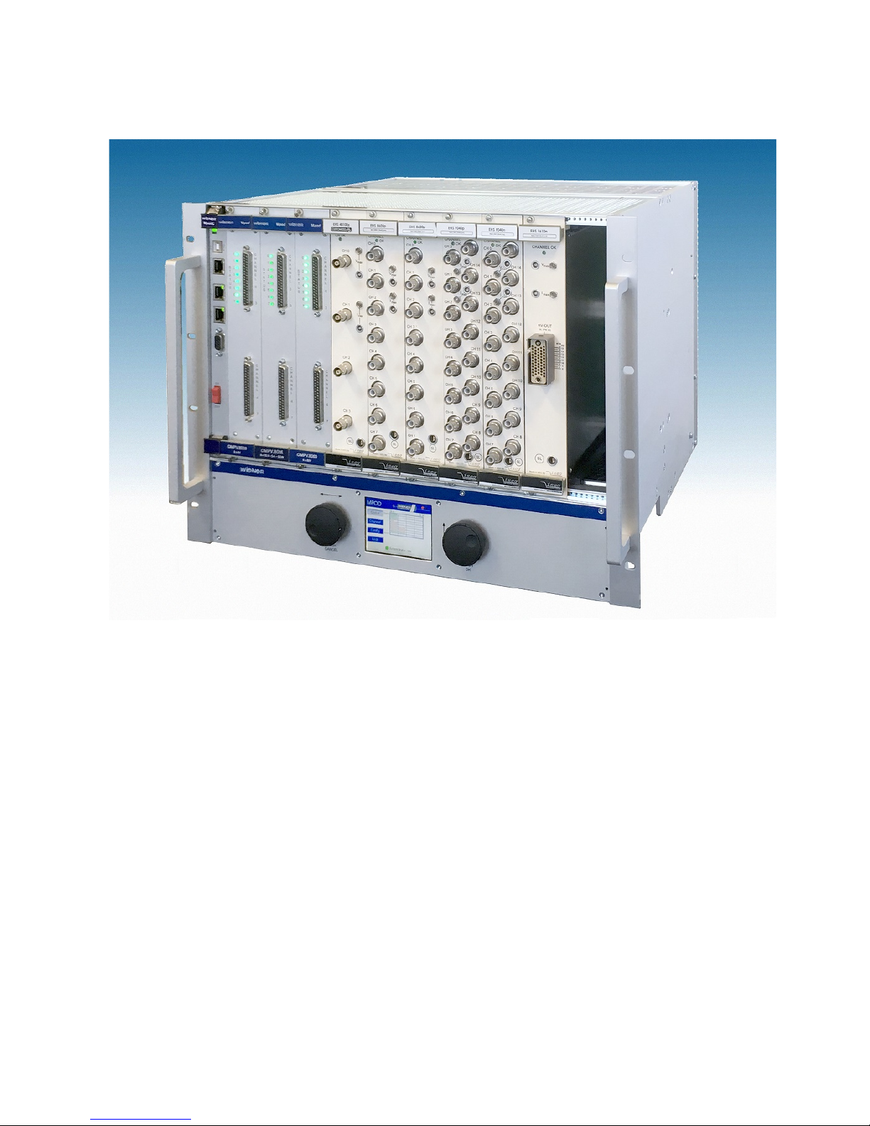
1 General Information
M OD crate with mixed low and high voltage modules
1.1 MPOD Features
M OD is a mainframe for multi-channel high voltage (HV) and low voltage (LV) power supply modules.
A unique flexibility is given by outfitting the M OD crate with either the LV or HV backplane only or
with both to allow combined use of LV and HV modules. The full size M OD crate has 10 slots for power
modules which provides a high number of output channels. Its modular design makes the customer able to
easily replace the fan tray, the controller, the primary power supply or the optional air filter.
Since 2017 with new compact design and integrated air filter.
●10 module slots for up to 80 LV channels / up to 480 HV channels
●8U high for bottom cooling air intake, optional dust filter
●Modules and controller outputs can be placed either at front or rear side (picture above shows front
side)
●LV: 8 channels (0- 8/16/30/60V/120V, 50W / channel, floating
●HV: 480 / 320/240 / 160 / 80 or 40 channels (0- 2.5/4/6kV/8kV/10kV), channel- or module wise
floating or common ground
●Low noise and ripple
●Individually controlled output channels (voltage and current), programmable warning and trip
levels
●M OD Controller with Ethernet (TC /I ) / CANbus / USB Combi-interface, Interlock
30. May 2018 6
●Ethernet port with integrated Web server, programmable with SNM protocol via TC /I , O C
●CE conform EN 50 081/82 part 1 (EN 50 022 B)
●safety in accordance with EN 60 950
●Sinusoidal mains current EN 61000-3-2
1.2 MPOD Crate standard types
The following crate types are standardized configurations with 8U high chassis. Optionally a filter frame is
available with bottom or front air inlet
Other configurations and mixed system with part of the crate outfitted with CI or VME backplanes are
available on request.
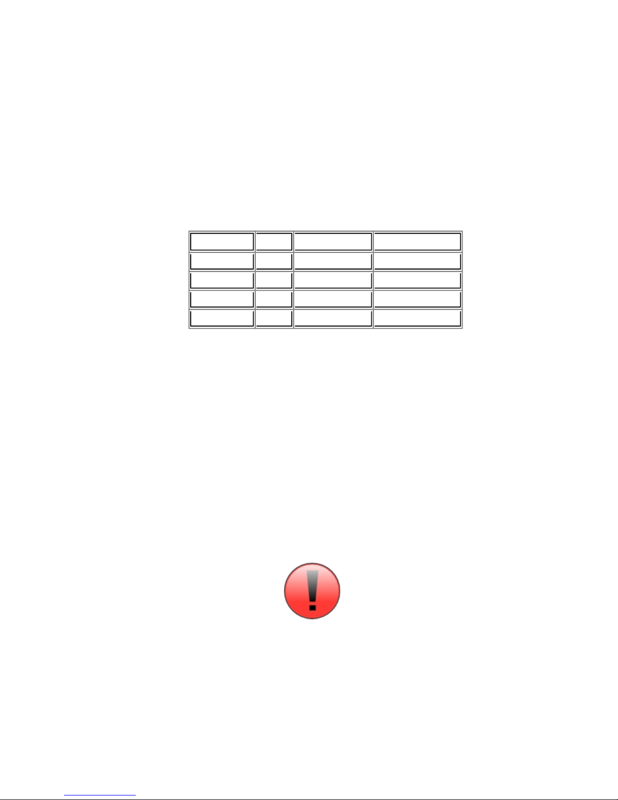
Type Slots Remote control
interface
Local control /
display
Backplane HV
power
Output
Position
MPOD EC 10 Ethernet, CAN, USB - HV/LV 600W front
MPOD EC R 10 Ethernet, CAN, USB - HV/LV 600W rear
MPOD LX 10 Ethernet, CAN, USB Yes, LCD HV/LV 600W front
MPOD LX R 10 Ethernet, CAN, USB Yes, LCD HV/LV 600W rear
MPOD EC LV 10 Ethernet, CAN, USB - LV - front
MPOD EC LV R 10 Ethernet, CAN, USB - LV - rear
MPOD EC HV 10 Ethernet, CAN, USB - HV 600W front
MPOD EC HV R 10 Ethernet, CAN, USB - HV 600W rear
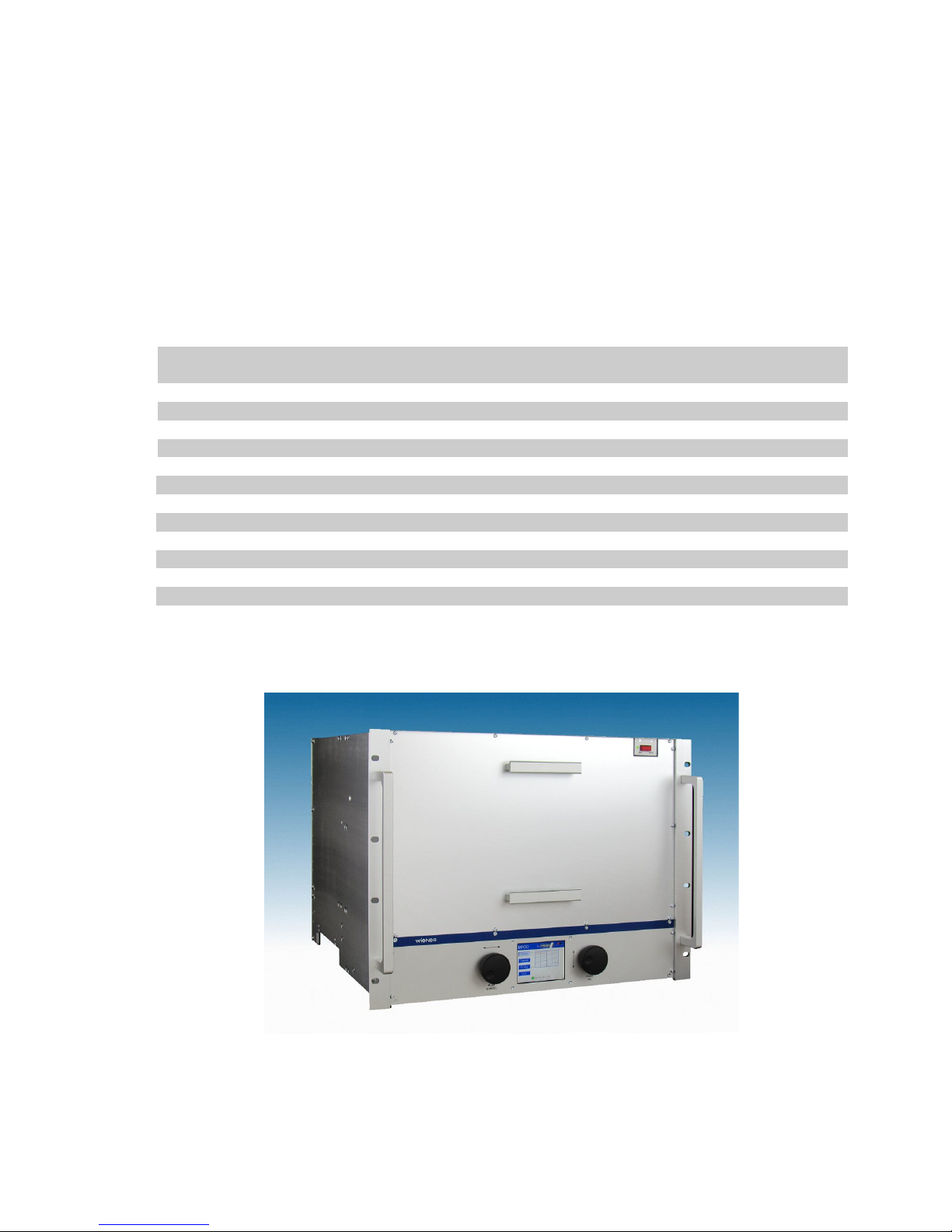
MPOD 2H 10 Ethernet, CAN, USB - HV 1200W front
MPOD 2H R 10 Ethernet, CAN, USB - HV 1200W rear
MPOD 2H LX 10 Ethernet, CAN, USB Yes, LCD HV 1200W front
MPOD 2H LX R 10 Ethernet, CAN, USB Yes, LCD HV 1200W rear
(CAN-bus for HV modules only, disabling Ethernet communication may be necessary for ISEG CAN-HV
control software)
M OD LX crate with reversed Card cage
Optionally, M OD can be outfitted with an internal removable air filter
30. May 2018 7

1.3 MPOD Mini crate
The WIENER M OD mini crate represents a compact 19” rack mountable chassis for up to 4
M OD low and high voltage modules. The M OD mini crate includes the primary power supply
with 600W power for high voltage modules as well as a cooling system with high performance
DC fan. It can be outfitted with HV backplane for us as a high voltage system only or with both
HV and LV backplanes.
The first half slot is reserved for the M OD Controller which manages the primary power
supplies and provides Ethernet, USB and CAN-bus interfaces for remote monitoring and control.
lease note that it is possible to switch the M OD crate off and on off remotely when the front
panel switch is in ON position.
M OD Mini crate with M OD controller and 2 high voltage + 1 low voltage module
1.4 MPOD Micro crate
The M OD micro crate is the smallest and low cost option for the WIENER multi-channel high
and low voltage power supply system. The M OD micro mainframe can house 1 or 2 plug-in low
or high voltage modules. The integrated M OD controller card provides10/100 Ethernet, CAN
bus and USB-2 interfaces.
M OD micro_2 crate with M OD controller ,one low voltage and one high voltage module
30. May 2018 8
2 LV Modules
The M V M OD Low Voltage modules are available with either 4 or 8 channels for different voltage
ranges with 8V, 16V, 30V, 60V maximum respectively. Special modules with up to 120V are under
development. All MV modules have the following features:
●6U height, 220mm deep fully shielded mechanics
●All DC outputs with individual return lines, individually sensed, floating channel to channel and
channel to chassis ground (125V, 500V tested)
●Low noise and ripple (<3mV at 20MHz bandwidth)
●Voltage and current settings / monitoring for each channel, 15 bit resolution, accuracy +/-0.1% of
full scale value
●Current monitoring and limiting for each channel, 15 bit resolution, accuracy +/-0.05% of full
scale value
●high stability, 0.2%/10k
●rogrammable channel parameters:
○voltage, under voltage / over voltage trip point
○current limit
○power, regulation type, internal / externl sense
○ramping speed up and down (1V/s … 500V/s)
○group features / error handling
●programming and monitoring via Ethernet (TC /I ) and USB
●Connectors: 2 x 8 pin high current sub-D, 37 pin sub-D for sense / control or
30. May 2018 9
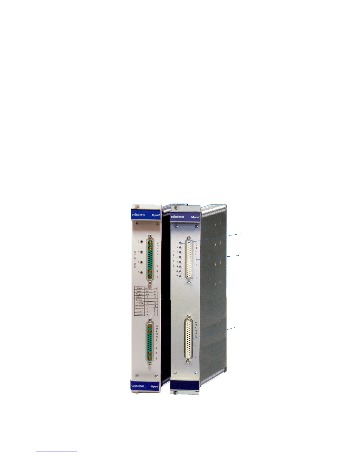
Status LED's for allchannels
DC terminal and sense
channel 0 to 3
DC terminal and sense
channel 4 to 7

2.1 MPOD Low Voltage Module Versions
MPOD Low Voltage Series 8 channels with floating ground
Type Channels Voltage I Max Peak Power V Res I Res Ripple
MPV 4008I 4 0 to 8V 20A 100W/ ch. 0.5mV 0.5mA <3mVpp
MPV 8008I 8 0 to 8V 10A 50W / ch. 0.5mV 0.5mA <3mVpp
MPV 8008LI 8 0 to 8V 5A 40W / ch. 0.5mV 0.25mA <3mVpp
MPV 4016I 4 0 to 16V 10A 100W/ ch. 1mV 0.25mA <2mVpp
MPV 8016I 8 0 to 15V 5A 50W / ch. 1mV 0.25mA <2mVpp
MPV 4030I 4 0 to 30V 5A 100W/ ch. 2mV 0.12mA <2mVpp
MPV 8030I 8 0 to 30V 2.5A 50W / ch. 2mV 0.12mA <2mVpp
MPV 4060I 4 0 to 60V 2A 100W/ ch. 4mV 0.06mA <2mVpp
MPV 8060I 8 0 to 60V 1A 50W / ch. 4mV 0.06mA <2mVpp
MPV 8120I 8 0 to 120V 100mA 50W / ch. 4mV 4 µA <10mVpp
I = Interlock, with sub D 37 pin female connector.
MPOD Low Voltage mating connectors
Sub D 37 extension cable 5m 37 Combined power/sense for 4 channels
Sub D 37 extension cable 25m 37 Combined power/sense for 4 channels
Connectors are IEC807 3/DIN41652 conform. Custom made cable sets are available on request.
30. May 2018 10
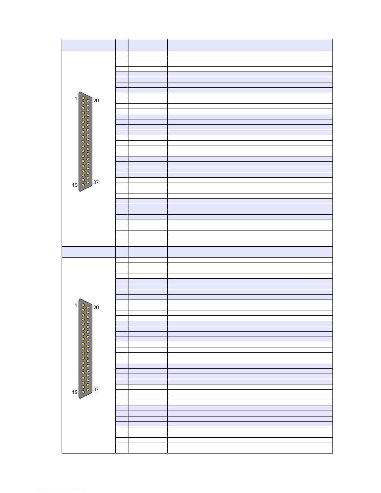
2.2 Combined Power & Sense Connector Pin Assignment MPV 8xxx(standard female type)
DSUB37 female
(Channel 0..3)
in Signal 2.2.1
U0-
Channel 0 negative output
20
U0+
Channel 0 positive output
2
U0-
Channel 0 negative output
21
U0+
Channel 0 positive output
3
U0-
Channel 0 negative output
22
U0+
Channel 0 positive output
4
S0-
Channel 0 negative sense input
23
S0+
Channel 0 positive sense input
5
U1-
Channel 1 negative output
24
U1+
Channel 1 positive output
6
U1-
Channel 1 negative output
25
U1+
Channel 1 positive output
7
U1-
Channel 1 negative output
26
U1+
Channel 1 positive output
8
S1-
Channel 1 negative sense input
27
S1+
Channel 1 positive sense input
9
U2-
Channel 2 negative output
28
U2+
Channel 2 positive output
10
U2-
Channel 2 negative output
29
U2+
Channel 2 positive output
11
U2-
Channel 2 negative output
30
U2+
Channel 2 positive output
12
S2-
Channel 2 negative sense input
31
S2+
Channel 2 positive sense input
13
U3-
Channel 3 negative output
32
U3+
Channel 3 positive output
14
U3-
Channel 3 negative output
33
U3+
Channel 3 positive output
15
U3-
Channel 3 negative output
34
U3+
Channel 3 positive output
16
S3-
Channel 3 negative sense input
35
S3+
Channel 3 positive sense input
17
INTERLOCK0
Optional interlock input: The four channels of this connector are
36
INTERLOCK1
enabled only if a signal is applied here
18
LOO 0
Safety Loop, LOO 0 and LOO 1 are connected to each other, no
37
LOO 1
connection to other potentials
19 CHASSIS Connected to chassis / front panel
SUB37 female
(Channel 4..7)
in Signal Bottom Connector
1
U4-
Channel 4 negative output
20
U4+
Channel 4 positive output
2
U4-
Channel 4 negative output
21
U4+
Channel 4 positive output
3
U4-
Channel 4 negative output
22
U4+
Channel 4 positive output
4
S4-
Channel 4 negative sense input
23
S4+
Channel 4 positive sense input
5
U5-
Channel 5 negative output
24
U5+
Channel 5 positive output
6
U5-
Channel 5 negative output
25
U5+
Channel 5 positive output
7
U5-
Channel 5 negative output
26
U5+
Channel 5 positive output
8
S5-
Channel 5 negative sense input
27
S5+
Channel 5 positive sense input
9
U6-
Channel 6 negative output
28
U6+
Channel 6 positive output
10
U6-
Channel 6 negative output
29
U6+
Channel 6 positive output
11
U6-
Channel 6 negative output
30
U6+
Channel 6 positive output
12
S6-
Channel 6 negative sense input
31
S6+
Channel 6 positive sense input
13
U7-
Channel 7 negative output
32
U7+
Channel 7 positive output
14
U7-
Channel 7 negative output
33
U7+
Channel 7 positive output
15
U7-
Channel 7 negative output
34
U7+
Channel 7 positive output
16
S7-
Channel 7 negative sense input
35
S7+
Channel 7 positive sense input
17
INTERLOCK0
Optional interlock input: The four channels of this connector are
36
INTERLOCK1
enabled only if a signal is applied here
18
LOO 0
Safety Loop, LOO 0 and LOO 1 are connected to each other, no
37
LOO 1
connection to other potentials
19 CHASSIS Connected to chassis / front panel
30. May 2018 11

2.3 Power & Combined Power & Sense Connector 4 channel MPV4x xxI1
30. May 2018 12

2.4 Sense & Control Connector Pin Assignment (modules with 8 channel + DSUB37 8)
DSUB37 male
(Channel 0..7)
in Signal Comment
1
S0+
Channel 0 positive Sense Input
20
S0-
Channel 0 negative Sense Input
2
reserved
21
reserved
3
S1+
Channel 1 positive Sense Input
22
S1-
Channel 1 negative Sense Input
4
reserved
23
reserved
5
S2+
Channel 2 positive Sense Input
24
S2-
Channel 2 negative Sense Input
6
reserved
25
reserved
7
S3+
Channel 3 positive Sense Input
26
S3-
Channel 3 negative Sense Input
8
reserved
27
reserved
9
S4+
Channel 4 positive Sense Input
28
S4-
Channel 4 negative Sense Input
10
reserved
29
reserved
11
S5+
Channel 5 positive Sense Input
30
S5-
Channel 5 negative Sense Input
12
reserved
31
reserved
13
S6+
Channel 6 positive Sense Input
32
S6-
Channel 6 negative Sense Input
14
reserved
33
reserved
15
S7+
Channel 7 positive Sense Input
34
S7-
Channel 7 negative Sense Input
16
reserved
35
reserved
17
reserved
36
reserved
18
reserved
37
reserved
19 reserved
Some pins are reserved for future funcionality
30. May 2018 13
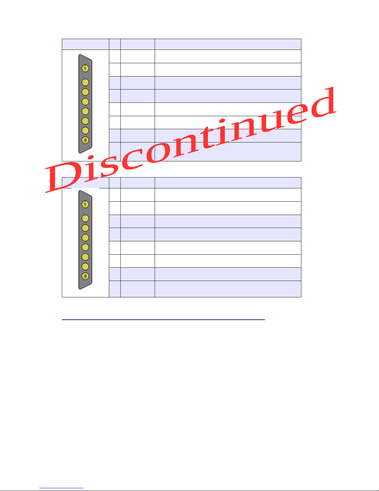
2.5 Power Connector Pin Assignment (modules with mixed DSUB37 + DSUB37 8)
DSUB37-8 female
(Channel 0..3)
in Signal Comment
1 U0+ Channel 0 positive Output
2 U0- Channel 0 negative Output
3 U1+ Channel 1 positive Output
4 U1- Channel 1 negative Output
5 U2+ Channel 2 positive Output
6 U2- Channel 2 negative Output
7 U3+ Channel 3 positive Output
8 U3- Channel 3 negative Output
DSUB37-8 female
(Channel 4..7)
in Signal Comment
1 U4+ Channel 4 positive Output
2 U4- Channel 4 negative Output
3 U5+ Channel 5 positive Output
4 U5- Channel 5 negative Output
5 U6+ Channel 6 positive Output
6 U6- Channel 6 negative Output
7 U7+ Channel 7 positive Output
8 U7- Channel 7 negative Output
Matching cable plug:
e.g. Erni TMC – - 8W8 male, unloaded connector (103448) + pins:
http://www.erni.com/DB/ DF/TMC/ERNI-D-SubHigh ower0101-e.pdf
30. May 2018 14

2.6 Combined Power & Sense Connector Pin Assignment MPV 4xxx (female 4 channel )
DSUB37 male
(Channel 0..3)
in Signal Top Connector
1
S0+
Channel 0 positive Sense Input
20
S0-
Channel 0 negative Sense Input
2
reserved
21
reserved
3
S1+
Channel 1 positive Sense Input
22
S1-
Channel 1 negative Sense Input
4
reserved
23
reserved
5
S2+
Channel 2 positive Sense Input
24
S2-
Channel 2 negative Sense Input
6
reserved
25
reserved
7
S3+
Channel 3 positive Sense Input
26
S3-
Channel 3 negative Sense Input
8
reserved
27
reserved
9
S4+
Channel 4 positive Sense Input
28
S4-
Channel 4 negative Sense Input
10
reserved
29
reserved
11
S5+
Channel 5 positive Sense Input
30
S5-
Channel 5 negative Sense Input
12
reserved
31
reserved
13
S6+
Channel 6 positive Sense Input
32
S6-
Channel 6 negative Sense Input
14
reserved
33
reserved
15
S7+
Channel 7 positive Sense Input
34
S7-
Channel 7 negative Sense Input
16
reserved
35
reserved
17
reserved
36
reserved
18
reserved
37
reserved
19 reserved
DSUB37 male
(Channel 4..7)
in Signal Bottom Connector
1
S0+
Channel 0 positive Sense Input
20
S0-
Channel 0 negative Sense Input
2
reserved
21
reserved
3
S1+
Channel 1 positive Sense Input
22
S1-
Channel 1 negative Sense Input
4
reserved
23
reserved
5
S2+
Channel 2 positive Sense Input
24
S2-
Channel 2 negative Sense Input
6
reserved
25
reserved
7
S3+
Channel 3 positive Sense Input
26
S3-
Channel 3 negative Sense Input
8
reserved
27
reserved
9
S4+
Channel 4 positive Sense Input
28
S4-
Channel 4 negative Sense Input
10
reserved
29
reserved
11
S5+
Channel 5 positive Sense Input
30
S5-
Channel 5 negative Sense Input
12
reserved
31
reserved
13
S6+
Channel 6 positive Sense Input
32
S6-
Channel 6 negative Sense Input
14
reserved
33
reserved
15
S7+
Channel 7 positive Sense Input
34
S7-
Channel 7 negative Sense Input
16
reserved
35
reserved
17
reserved
36
reserved
18
reserved
37
reserved
19 reserved
30. May 2018 15

2.7 Combined Power & Sense Connector Pin Assignment MPV 2xxx (female 2 channel)
DSUB37 female
(Channel 0)
in Signal Top connector
1 U0- Channel 0 negative output
20 U0+ Channel 0 positive output
2 U0- Channel 0 negative output
21 U0+ Channel 0positive output
3 U0- Channel 0 negative output
22 U0+ Channel 0 positive output
4 U0- Channel 0 negative output
23 U0+ Channel 0 positive output
5 U0- Channel 0 negative output
24 U0+ Channel 0 positive output
6 U0- Channel 0 negative output
25 U0+ Channel 0 positive output
7 U0- Channel 0 negative output
26 U0+ Channel 0 positive output
8 S0- Channel 0 negative sense input
27 S0+ Channel 0 positive sense input
9 U1- Channel 1 negative output
28 U1+ Channel 1 positive output
10 U1- Channel 1 negative output
29 U1+ Channel 1 positive output
11 U1- Channel 1 negative output
30 U1+ Channel 1 positive output
12 U1- Channel 1 negative output
31 U1+ Channel 1 positive output
13 U1- Channel 1 negative output
32 U1+ Channel 1 positive output
14 U1- Channel 1 negative output
33 U1+ Channel 1 positive output
15 U1- Channel 1 negative output
34 U1+ Channel 1 positive output
16 S1 - Channel 1 negative sense input
35 S1 + Channel 1 positive sense input
17 INTERLOCK0 Optional interlock input: The channel of this connector is
36 INTERLOCK1 enabled only if a signal is applied here
18 LOO 0 Safety Loop, LOO 0 and LOO 1 are connected to each other, no
37 LOO 1 connection to other potentials
19 CHASSIS Connected to chassis / front panel
DSUB37 female
(Channel 1)
in Signal Bottom Connector
1
U2-
Channel 2 negative output
20
U2+
Channel 2 positive output
2
U2-
Channel 2 negative output
21
U2+
Channel 2 positive output
3
U2-
Channel 2 negative output
22
U2+
Channel 2 positive output
4
U2-
Channel 2 negative output
23
U2+
Channel 2 positive output
5
U2-
Channel 2 negative output
24
U2+
Channel 2 positive output
6
U2-
Channel 2 negative output
25
U2+
Channel 2 positive output
7
U2-
Channel 2 negative output
26
U2+
Channel 2 positive output
8
S2-
Channel 2 negative sense input
27
S2+
Channel 2 positive sense input
9
U3-
Channel 3 negative output
28
U3+
Channel 3 positive output
10
U3-
Channel 3 negative output
29
U3+
Channel 3 positive output
11
U3-
Channel 3 negative output
30
U3+
Channel 3 positive output
12
U3-
Channel 3 negative output
31
U3+
Channel 3 positive output
13
U3-
Channel 3 negative output
32
U3+
Channel 3 positive output
14
U3-
Channel 3 negative output
33
U3+
Channel 3 positive output
15
U3-
Channel 3 negative output
34
U3+
Channel 3 positive output
16
S3-
Channel 3 negative sense input
35
S3+
Channel 3 positive sense input
17
INTERLOCK0
Optional interlock input: The channel of this connector is
36
INTERLOCK1
enabled only if a signal is applied here
18
LOO 0
Safety Loop, LOO 0 and LOO 1 are connected to each other, no
37
LOO 1
connection to other potentials
19 CHASSIS Connected to chassis / front panel
30. May 2018 16

2.8 SAFETY LOOP and optional INTERLOCK functionality of MPV modules
The SAFETY LOO pins provide a closed connection between LOO 0 and LOO 1 in case the properly
wired DSUB37 connector is plugged into the M V module. It does not have any functionality inside the
module!
The Interlock features is only available on M V 8xxxI modules. Older or other modules that do not have
the "I" (interlock) in the part number / name , will not interlock. Furthermore the interlock will work on the
bank of 4 channels on each sub-d 37 pin connector.
Using a 5-14V source, apply +V to pin 36 and 0V to pin 17 of the M OD module sub-d 37 pin connector
(see pin layout in chapter 2.2).
In order to use the Interlock function each channel has to be enabled for this. In MUSEcontrol Software,
right mouse click on the channel and check in the “Output Configuration” window the check mark “Enable
External Inhibit” accordingly.
30. May 2018 17

3 HV Modules
M OD high voltage modules are manufactured by ISEG (www.iseg-hv.com). For technical
details please refer to the ISEG manuals and data sheets of the EHS, EBS, EDS and EHQ
(discontinued) multi channel high voltage modules. General features are:
●High Voltage modules with 4, 8, 16, 24, 32 or 48 individually controlled channels
●Maximum voltage range from 500V up to 10 kV
●Extremely low noise and ripple: <5mVpp to <10mVpp
●All DC outputs floating or common ground depending on module type
●Voltage and current settings / monitoring for each channel, 16 to 21 bit resolution
●Current monitoring and limiting for each channel, 16 to 21 bit resolution
●rogrammable channel parameters, group features
●output connectors:
8 channel modules SHV or REDEL (<4kV) multi pin
Kings for 8kV and 10kV (4 channels only)
16 channel modules SHV or REDEL (<4kV) multi pin
24 channel modules REDEL (<4kV) multi pin or AM 201311-3
32 channel modules REDEL multi pin
48 channel modules RADIAL multi-pin
ISEG high voltage modules with 4 channels KINGS (10kV), 8 and 16 channels SHV, and 8 / 16 channels
REDEL multi-pin connectors (from left to right)
30. May 2018 18

M OD crate with rear side module option and air filter outfitted with ISEG EDS, EBS and EHS high
voltage modules and wired safety loop.
30. May 2018 19
This manual suits for next models
1
Table of contents
Other Wiener Power Supply manuals


Popular Power Supply manuals by other brands


Cooper Wheelock
Cooper Wheelock POWERPATH PS-24-8MC installation instructions

Pulsar
Pulsar PSBOC15512110 manual

Sonelco
Sonelco P3226 manual

RCI
RCI 10-175UL Installation and specification manual

BE QUIET!
BE QUIET! PURE POWER 10 user manual

Pentair Pool Products
Pentair Pool Products IntelliChlor PC100 Installation and user guide