Wiener PL512 User manual

28. May 2013 1 *00679.A4
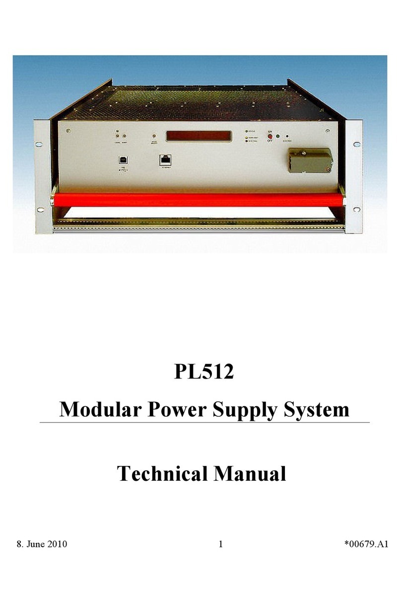
PL512/PL506
Modular Power Supply System
Technical Manual

General Remar s
The only purpose of this manual is a des ription of the produ t. It must not be interpreted as
a de laration of onformity for this produ t in luding the produ t and software.
W-Ie-Ne-R revises this produ t and manual without noti e. Differen es of the des ription in
manual and produ t are possible.
W-Ie-Ne-R ex ludes ompletely any liability for loss of profits, loss of business, loss of use
or data, interrupt of business, or for indire t, spe ial in idental, or onsequential damages of
any kind, even if W-Ie-Ne-R has been advises of the possibility of su h damages arising
from any defe t or error in this manual or produ t.
Any use of the produ t whi h may influen e health of human beings requires the express
written permission of W-Ie-Ne-R.
Produ ts mentioned in this manual are mentioned for identifi ation purposes only. Produ t
names appearing in this manual may or may not be registered trademarks or opyrights of
their respe tive ompanies.
No part of this produ t, in luding the produ t and the software may be reprodu ed,
transmitted, trans ribed, stored in a retrieval system, or translated into any language in any
form by any means with the express written permission of W-Ie-Ne-R.
Control Cabinet
In the ontext of this user manual, the ontrol abinet must fulfill the requirements on fire-
prote tive en losures a ording to EN 60950 / IEC 60950 / UL 60950.
All devi es are intended for operation in ontrol abinets or in losed areas. The LAN
onne tion and all wire onne tions between the different system parts must be done via
shielded able with ondu tive onne tor shells, whi h are fixed with s rews.
Furthermore, an additional fire-prote tive en losure is required whi h must not affe t proper
air ir ulation.
Mains Voltage and Connection
The Power supplies are equipped with a “World”- mains input (rated voltage range: 100-240
VAC, frequen y: 50-60 Hz, rated urrent: 16 A). Before onne ting to the mains please
double- he k orresponden e.
The mains input onne tion at the power supply side is des ribed in hapter 2.1 (AC Mains
Conne tion) at page 2.
Safety
After onne ting the Power box to the mains, the mains input module is powered
permanently. Filter and storage apa itors of the power fa tor orre tion module are harged
with about 400VDC. Any DC-On-Signal as well as a power swit h at ontrol board (if any
installed) operates as a low voltage DC on/off swit h only and not as a mains breaker.
Therefore it becomes dangerous if the box cover is open. In this case a lot of
components on high voltage potential get touchable!
Before starting any ind of wor inside the power box remove
the unit from mains and wait a couple of minutes with your
activities! Discharge the primary DC filter-capacitors by use of
a well insulated 22 ohm 10W resistor.
We recommend in case of any malfunction to send the power
box to Wiener or to one of our representative for service
2. April 2014 i *00679.A4

Declaration of Conformity
Low Voltage Dire tive 73/23/EEC and EMC Dire tive Art. 10.1 of 89/336/EEC
W-Ie-Ne-R
Plein & Baus GmbH
de lare under our own responsibility that the produ t
PL5 / PL6, F8-12
Items: 0P00.xxxx; 0P01.xxxx; 0P04.xxxx; 0M11.xxxx;
0M21.xxxx
is in a ordan e with the following standards or standardized do uments:
1. EN 60 950-1:2001
+ Corr:2004-09 Niederspannungsri htlinie [low voltage
dire tive]
2. EN 61 000-6-3:2001 Störaussendung EMA [RF emission]
EN 55 022:1998
+ Corr:2001 + A1:2000 Kl. B
Störspannung [ ondu ted noise]
EN 55 022:1998
+ Corr:2001 + A1:2000 Kl. B
Störfeldstärke [radiated noise]
EN 61 000-3-2:2001 Obers hwingungen [harmoni s]
EN 61 000-3-3:1995 +Corr:1997 +A1:2001 Spannungss hwankungen [fli ker]
3. EN 61 000-6-2:2001 Störfestig eit EMB [immunity]
EN 61 000-4-6:1996 + A1:2001 HF-Einströmung [inje ted HF urrents]
EN 61 000-4-3:1996 + A1:1998 + A2:2001 HF-Felder [radiated HF fields] in l.
”900MHz”
EN 61 000-4-4:1995 + A1:2001 Burst
EN 61 000-4-5:1995 + A1:2001 Surge
EN 61 000-4-11:1994 + A1:2000 Spannungs-Variationen [voltage
variations]
EN 61 000-4-2:1995 + A1:1998 + A2:2001 ESD
Conditions:
This unit is not a final produ t and is foreseen for use inside a losed abinet. The supplying
of loads over long distan es (>3m) needs possibly additional RF reje tion hardware to get in
onformity of the definition. Admitted for powering by all mains.
Name and signature of authorized person Pla e and Date
Juergen Baus
Te hn. Dire tor Aug. 2006
2. April 2014 ii *00679.A4

Contents
General Remar s..............................................................................................................i
Declaration of Conformity...............................................................................................ii
1 General Information............................................................................................................1
2 PL512/PL506 Power Box....................................................................................................2
2.1 AC Mains Connection................................................................................................2
2.2 Main Switch................................................................................................................3
2.3 USB Connector...........................................................................................................3
2.4 Ethernet Connector....................................................................................................3
2.5 Water Cooling Connection (Optional)......................................................................3
2.6 Global Reset Input (Optional)..................................................................................4
2.7 Channel-Wise Interloc Input (Optional)...............................................................5
2.8 Global Stop and Start Inputs (Optional)..................................................................5
2.9 Alphanumeric Display (Optional).............................................................................6
2.9.1 LED Des ription...................................................................................................7
2.9.2 Fun tion of the Swit hes......................................................................................7
2.9.3 Main Operating Modes and Asso iated Submenus...............................................8
2.10 Power Output and Sense Connections PL512........................................................9
2.11 Power Output and Sense Connections PL506......................................................10
3 PL512/PL506 Control and Setup via USB........................................................................10
3.1 Installation................................................................................................................11
3.2 The Main Window....................................................................................................12
3.3 Description of the Menu Items................................................................................12
3.3.1 Read Power Supply Data From File Dialog.........................................................13
3.3.2 Output Configuration Dialog...............................................................................13
3.3.3 Global and Network Configuration Dialog..........................................................15
4 PL-506/512 Wiring and First Use Instru tions ..............................................................16
4.1 Power Bins PBN506/PBN512..................................................................................16
4.2 Sense Connections / Mode........................................................................................16
4.3 Load Connections.....................................................................................................17
4.4 MUSEControl...........................................................................................................18
5 Web Server........................................................................................................................21
6 SNMP Control...................................................................................................................21
7 OPC Server........................................................................................................................30
8 Power Bins PBN506/PBN512...........................................................................................31
Appendix A: Data Sheet.......................................................................................................33
Appendix B: Ordering Information......................................................................................36
Appendix C: SNMP OID Tree.............................................................................................37
Appendix D: Parallel Conne tion of Output Channels.........................................................40
2. April 2014 iii *00679.A4

Figures
Figure 2.1: PL512/PL506 Front Side with Interlock and Water- ooled Option..........2
Figure 2.2: PL512/PL506 Front Side with Display Option..........................................2
Figure 2.3: PL512 Rear Side (Power Output onnections)......................................9
Figure 2.4: PL506 Rear Side (Power Output onnections)....................................10
Figure 2.5: PL512 Rear Side (Power Output onnections)....................................10
Figure 7.1: PBN512 -3U RATO Power Bin..............................................................17
Figure 7.2: PBN506 -3U RASO Power Bin (with PL506 Power Supply inserted).....18
Figure 7.3: urrent Bar Dimensions........................................................................26
Figure 7.4: Two hannels Parallel...........................................................................28
Figure 7.5: Three hannels Parallel........................................................................28
Figure 7.6: Four hannels Parallel..........................................................................28
Tables
Table 1: A Mains Input onnector Pin Assignment.................................................2
Table 2: USB onnector Pin Assignment..................................................................3
Table 3: Ethernet onnector Pin Assignment............................................................3
Table 4: Global Reset onnector Pin Assignment.....................................................4
Table 5: hannel-Wise Interlock onnector Pin Assignment.....................................5
Table 6: Sense onnector Pin Assignment...............................................................9
2. April 2014 iv *00679.A4

1 General Information
Features
●up to 12 independent processor controlled, potential free outputs
●up to 3 W DC output power
●Programmable output voltage, current limit and rise/fall time
●Measurement of output voltages and current
●Fully controlled, programmable trip thresholds (min./max. sense voltage, max terminal
voltage, max. current, power, temperature)
●PC-Control (connected to USB) with free available software
●Ethernet connection IEEE 802.3 10BASE-T and IEEE 802.3u 100BASE-TX
●WWW-Server integrated, full control via SNMP protocol
●OPC server available
●Three different voltage regulation modes programmable: Fast – Moderate - Slow
●Extremely low noise and ripple
●CE conform EN 50 081/82 part 2 or 1, safety in accordance with EN 60 950
●Sinusoidal mains current EN 61000-3-2
●Optional alphanumeric display
●Optional global interloc
●Optional channel-wise interloc
●Optional direct water cooling
●Optional Power Bin: Exchange of the power box without disconnecting the cabling to the
load
28. May 2013 1 *00679.A4

2 PL512/PL506 Power Box
The PL512/PL506 front appearan e differs slightly, depending on the existing options.
2.1 AC Mains Connection
The AC input onne tions are made with the Hirs hmann onne tor series ST.
We re ommend the mating able plug STAK3N with the lo king retainer STASI3.
AC Input Pin Signal Comment
1
Phase
2
Return, Neutral
Cable wire olor: bla k or brown wire
Cable wire olor: blue
3
unused
Earth Prote tive Earth Safety Ground, Cable wire olor: green / yellow
Table 1: AC Mains Input Conne tor Pin Assignment
28. May 2013 2 *00679.A4
Figure 2.2: PL512/PL506 Front Side with Display Option
Figure 2.1: PL512/PL506 Front Side with Interlo k and Water-Cooled Option

2.2 Main Switch
The green illuminated ro ker swit h works as a global inhibit input.
●0 Power outputs disabled
●I Swit h is lighting, power outputs may be enabled by the remote ontrol.
This swit h is a logi swit h only. It does not dis onne t the mains supply.
With the Alphanumeric Display Option the swit h is omitted.
2.3 USB Connector
USB So ket Pin Signal Comment
1
VCC
2
D-
3
D+
4GND
Table 2: USB Conne tor Pin Assignment
This is the standard USB onne tor type B.
2.4 Ethernet Connector
RJ45 So ket Pin Signal Comment
1
TX+
2
TX-
3
RX+
4
GND 1
5
GND 1
6
RX-
7
GND 2
8
GND 2
Table 3: Ethernet Conne tor Pin Assignment
This is the standard NIC onfiguration. You need a 1:1- able to onne t a to a HUB, or a cross-
over cable to connect to another NIC (e.g. a computer). There is no automatic signal crossing like
with some routers.
2.5 Water Cooling Connection (Optional)
The water onne tions are made with qui k ouplings series LC 6.4 mm from Colder Products
Company (CPC). We re ommend an elbow mating plug with shutoff, e.g. LCD230-04.
Consider that water inlet and water outlet are not ex hangeable.
The safety valve may not be readjusted by the ustomer.
28. May 2013 3 *00679.A4

2.6 Global Reset Input (Optional)
The global reset input (POWER_INHIBIT) is provided to for e all outputs to be swit hed off.
●onne ted to GND Power outputs disabled
●floating Power outputs may be enabled by the remote ontrol
DSUB25 female Pin Signal Comment
1
NC
reserved
14
NC
reserved
2
NC
reserved
15
NC
reserved
3
NC
reserved
16
NC
reserved
4
NC
reserved
17
NC
reserved
5
NC
reserved
18
NC
reserved
6
NC
reserved
19
NC
reserved
7
NC
reserved
20
NC
reserved
8
NC
reserved
21
NC
reserved
9
NC
reserved
22
NC
reserved
10
NC
reserved
23
NC
reserved
11
NC
reserved
24
NC
reserved
12
NC
reserved
25
GND
Ground of the aux. supply, onne ted to USB ground
13
POWER_INHIBIT
Inhibit input
Table 4: Global Reset Conne tor Pin Assignment
The signals shall be onne ted by an isolated onta t (e.g. relays), and must not be onne ted to
other potentials.
The input has an internal 10 kΩ pull-up resistor to 5V and an input impedan e of 10 kΩ.
It is possible to invert the logi of this signal by hanging a jumper swit h inside of the power box..
Jumper at Pin POWER_INHIBIT Input Fun tionality
1 – 2 open power disabled (INTERLOCK)
onne ted to GND power enabled
2 – 3 open power enabled
onne ted to GND power disabled (RESET)
28. May 2013 4 *00679.A4

2.7 Channel-Wise Interloc Input (Optional)
The hannel-wise interlo k inputs are provided to for e a dedi ated output to be swit hed off.
DSUB25 female Pin Signal Comment
1
Interlo k U0 +
14
Interlo k U0 -
2
Interlo k U1 +
15
Interlo k U1 -
3
Interlo k U2 +
16
Interlo k U2 -
4
Interlo k U3 +
17
Interlo k U3 -
5
Interlo k U4 +
18
Interlo k U4 -
6
Interlo k U5 +
19
Interlo k U5 -
7
Interlo k U6 +
20
Interlo k U6 -
8
Interlo k U7 +
21
Interlo k U7 -
9
Interlo k U8 +
22
Interlo k U8 -
10
Interlo k U9 +
23
Interlo k U9 -
11
Interlo k U10 +
24
Interlo k U10 -
12
Interlo k U11 +
25
Interlo k U11 -
13
reserved
Table 5: Channel-Wise Interlo k Conne tor Pin Assignment
Ea h interlo k input is galvani ally isolated (opto ouplers). If a hannel is interlo ked, it is not
possible to swit h it on.
Signal level:
interlo ked: -10 V ... +0.8 V
not interlo ked: +2.2 V ... +10 V (input impedan e 1 kΩ + LED, so higher input
voltages an be used if an external resistor is implemented.)
2.8 Global Stop and Start Inputs (Optional)
This inputs allow to swit h off the outputs hannels (emergen y stop) or to swit h on all power
supply outputs (e.g. used for maintenan e) .
28. May 2013 5 *00679.A4

DSUB25 female Pin Signal Comment
1
NC
reserved
14
NC
reserved
2
NC
reserved
15
NC
reserved
3
NC
reserved
16
NC
reserved
4
NC
reserved
17
NC
reserved
5
NC
reserved
18
NC
reserved
6
NC
reserved
19
NC
reserved
7
NC
reserved
20
NC
reserved
8
NC
reserved
21
NC
reserved
9
NC
reserved
22
NC
reserved
10
NC
reserved
23
NC
reserved
11
NC
reserved
24
NC
reserved
12
STOP
reserved
25
GND
Ground of the aux. supply, onne ted to USB ground
13
START
Inhibit input
Table 6: Global Stop and Start Conne tor Pin Assignment
The signals shall be onne ted by a dry onta t (e.g. relay), and must not be onne ted to other
potentials.
The input has an internal 330 Ω pull-up resistor to 5V and an input impedan e of 1 kΩ.
Signal Fun tionality
STOP If this signal is onne ted to GND (dry onta t lose), all power supply outputs
are swit hed off. This fun tionality has priority over all other fun tions, it is not
possible to swit h outputs on in this state
START If this signal is onne ted to GND (dry onta t lose), all power supply outputs
are swit hed on. They will only be swit hed off in ase of an emergen y swit h
off aused by the supervision logi of the power supply.
If this signal is not onne ted (dry onta t open), power supply outputs may be
swit hed on/off via SNMP or with the display ontrol.
2.9 Alphanumeric Display (Optional)
This option allows the setup and display of some power supply items with toggle swit hes.
28. May 2013 6 *00679.A4

2.9.1 LED Des ription
●Power LED (green, 5mm) Lighting if the PL512/PL506 is operating. Channels may be
on.
●Status LED (green, 3mm) Lighting if the main pro essor is working properly .
●Overheat (yellow) Lighting if the operating temperature inside of the
power supply is too high.
●SYS FAIL (red) Pro essor malfun tion.
2.9.2 Fun tion of the Swit hes
After the PL512/PL506 has been swit hed on by pushing the “Power” swit h up, the main operation
modes an be sele ted by pushing the “Mode Sele t” swit h up or down.
Many main operating modes do have one or more submenus, whi h an be a essed by a spe ial
pro edure.
You will use the following swit hes of the PL512/PL506:
Symbol Des ription Remarks
P▲ Push “Power” swit h up (ON) Main power supply is off:
Swit h the power supply on. All power
hannels are off.
Display shows a switched off channel:
Swit h this hannel on.
Submenu:
OK button. Used to enter the sele ted
submenu, request to hange a value, a ept
the hanges.
P▼ Push “Power” swit h down
(OFF)
Display shows a switched off channel:
Swit h the main power supply and all
hannels off.
Display shows a switched on channel:
Swit h this hannel off.
Submenu:
CANCEL button. Used to leave a submenu,
dis ard the hanges.
M▲ Push “Mode Sele t” swit h up Main operating mode:
Sele t the next operating mode.
Submenu:
Change the sele ted item to the next possible
state.
M▼ Push “Mode Sele t” swit h
down
Main operating mode:
Sele t the previous operating mode.
Submenu:
Change the sele ted item to the previous
possible state.
28. May 2013 7 *00679.A4

The following example des ribes the detailed steps to enter a sub menu and hange the IP gateway
address.
Des ription Swit h Display 1
swit h the rate on P▲ U0 5.01V 1.2A
sele t the requested main
operation mode
M▲ or M▼ (until right mode is
displayed)
TCPIP: no link
enter submenu M▲(push and hold), P▲ Config: Wait
hold both swit hes up Config: Wait...
after 4 se onds you an Config: Ready !
release the swit hes TCPIP Address
1 2.168. 1.80
Sele t submenu “TCPIP
Gateway”
M▲ or M▼ (until right menu is
displayed)
TCPIP Gateway
1 2.168. 1. 4
Enter this menu P▲ 1 2.168. 1. 4
Change the value M▲ or M▼ 1 6.168. 1. 4
A ept hange, to next item P▲ 1 6.168. 1. 4
Ready, ba k to submenu
sele tion
P▲ TCPIP Gateway
1 6.168. 1. 4
Ready, leave submenu M▼ TCPIP: no link
2.9.3 Main Operating Modes and Asso iated Submenus
Operating
Mode
Submenu Display
Display voltage and urrent of the sele ted output hannel U0 5.01V 72.A
Display the TCP/IP connection state
Possible values & symbols are:
no link (no able onne ted)
10M ( onne ted to 10M network)
100M ( onne ted to 100M network)
HD (half duplex)
FD (full duplex)
↓, ↑, ↕ (Frame re eived, transmitted, both)
Ethernet 100M FD
1 Display: Two lines: displayed alternating, alternate ba kground olor: blinking
28. May 2013 8 *00679.A4

Operating
Mode
Submenu Display
Change the TCP/IP address TCPIP Address
1 2.168. 1.80
Change the TCP/IP subnet mask TCPIP SubnetMask
255.255.255.224
Change the TCP/IP gateway address TCPIP Gateway
1 2.168. 1. 4
Allow writes (e.g. swit h on/off) via the web
server
HTTP:read/write
Change TCP/IP negotiation settings TCPIPnegotiation
AutoNegotiation
Display of the ethernet hardware address (MAC).
This address is written at the type plate, too.
TCPIP MAC Addres
0050-C22D-C231
Change the TCP/IP port of the web server HTTP Port 80
Change the TCP/IP port of the SNMP server SNMP Port 161
Restore the default SNMP settings ( ommunity
strings)
SNMP Default No
2.10 Power Output and Sense Connections PL512
Figure 2.3: PL512 Rear Side (Power Output Conne tions)
The low voltage DC output at the rear side of the power supply is provided by 4 mm so kets The
hannels are arranged from left to right starting with U0. Positive output is up and negative output is
down.
28. May 2013 9 *00679.A4

The sense lines are routed to three DSUB onne tors (four hannels ea h).
SUB9 male Pin Left Conne tor (U0..U3) Middle Conne tor (U4..U7) Right Conne tor (U8..U11)
1 U0 Sense + U4 Sense + U8 Sense +
6 U0 Sense - U4 Sense - U8 Sense -
2 U1 Sense + U5 Sense + U9 Sense +
7 U1 Sense - U5 Sense - U9 Sense -
3 U2 Sense + U6 Sense + U10 Sense +
8 U2 Sense - U6 Sense - U10 Sense -
4 U3 Sense + U7 Sense + U11 Sense +
9 U3 Sense - U7 Sense - U11 Sense -
5 not onne ted not onne ted not onne ted
Table 7: Sense Conne tor Pin Assignment
2.11 Power Output and Sense Connections PL506
Figure 2.5: PL506 Rear Side (Power Output Conne tions)
The low voltage DC output at the rear side of the power supply is provided by 6 mm or 8mm so kets
. The hannels are arranged from left to right starting with U0. Positive output is up and negative
output is down.
The sense lines are routed to three DSUB onne tors (2 hannels ea h).
DSUB9 male Pin Left Conne tor (U0..U3) Middle Conne tor (U4..U7) Right Conne tor (U8..U11)
1 U0 Sense + U2Sense + U4 Sense +
6 U0 Sense - U2Sense - U4 Sense -
2 U1 Sense + U3Sense + U5 Sense +
7 U1 Sense - U3Sense - U5 Sense -
3 not onne ted not onne ted not onne ted
8 not onne ted not onne ted not onne ted
4 not onne ted not onne ted not onne ted
9 not onne ted not onne ted not onne ted
5 not onne ted not onne ted not onne ted
Table 8: Sense Conne tor Pin Assignment
3 PL512/PL506 Control and Setup via USB
The PL512/PL506 an be ontrolled with the MUSE ontrol software. Without the Display option
this is the only way to hange the network (TCP/IP) settings.
28. May 2013 10 *00679.A4
Figure 2.4: PL506 Rear Side (Power Output Conne tions)

The USB interfa e is primarily intended to be used to onfigure the power
supply. The Ethernet onne tion is designated for remote ontrol and
monitoring.
Requirements
●X86-Computer with USB onne tion (USB2 re ommended)
●Mi rosoft Windows XP/VISTA/& or W8
Features
●Setup of the TCP/IP network parameters
●Global overview of all power supply hannels
●Detailed onfiguration of the power supply hannels
●Save and reload of onfiguration data
3.1 Installation
The installation software (MUSE ontrol-x.x.x.x.msi) is free available at the download area of our
website (www.wiener-d. om → Support → Downloads).
Please install the software before onne ting the power supply to the USB. The
ne essary USB-driver is in luded in the installation.
After downloading and exe uting the
software Windows may omplain that the
supplier of the software ould not be
verified. Ignore this warning and sele t
“Exe ute”.
Next the MUSE ontrol Setup Wizard
wel ome s reen is displayed. Cli k “Next”,
a ept the li ense agreement and take a
look at the ReadMe notes.
Now you may hange the default
installation folder and start the installation.
Now onne t the PL512/PL506 with your
mains supply and use an USB able to onne t the omputer with the PL512/PL506.
The omputer will dete t the new onne ted hardware and ask to onne t to Windows Update.
Sele t “No” and li k “Continue”.
Then a ept the “Automati install the software” sele tion by li king “ ontinue”.
28. May 2013 11 *00679.A4

Now the USB driver software be installed. To a ess your power supply, exe ute the “WIENER
USB Power Supply Control” appli ation via your start menu.
3.2 The Main Window
After starting the appli ation the main window shows a hannel overview.
The measured sense voltage (Usense), urrent (Imodule) and terminal voltage (Umodule) and a
global status of ea h
hannel are displayed.
Cli king with the left
mouse button at a
hannel toggles the
power state (OFF → ON
or ON → OFF).
Cli king with the right
mouse button opens the
output onfiguration
menu of this hannel.
3.3 Description of the Menu Items
●File » Read Power Supply Configuration from File
Opens the Read Power Supply Data From File Dialog.
●File » Save Power Supply Configuration to File
Saves the omplete power supply onfiguration to disk.
●Swit h » All On
●Swit h » All Off
Swit hes all power supply hannels on or off.
●Swit h » Group 1 On
●Swit h » Group 1 Off
●Swit h » Group 2 On
●Swit h » Group 2 Off
This are ommands to demonstrate the grouping fun tions of the PL512/PL506. The default
fa tory setting is group 1 for hannels 0..5 and group 2 for hannels 6..11.
●Sele tOutput
28. May 2013 12 *00679.A4

Sele t the next existing hannel for the other dialogs. The urrent hannel is displayed at the
title bar.
●DVM
Opens a large window showing the measurement data of one hannel.
●OutputConfiguration
Opens the Output Configuration Dialog.
●OutputCalibration
This dialog is reserved for servi e personal.
●System » Configuration
Opens the Global and Network Configuration Dialog.
●System » Firmware Update
Allows to update the firmware of the main pro essor.
●Stop
●Start
Allow to interrupt and resume the ommuni ation with the PL512/PL506.
●Help » Info
Here you have a ess to the version number of the software.
3.3.1 Read Power Supply Data From File Dialog
This dialog an be used to opy a XML onfiguration file from disk to the PL512/PL506.
It is possible to opy
ea h onfiguration file
hannel to its
orresponding power
supply hannel (e.g.
U0 → U0, U1 →
U1, ...) or to opy one
onfiguration file
hannel to multiple
power supply
hannels.
3.3.2 Output Configuration Dialog
This dialog allows the detailed onfiguration of ea h power supply hannel.
The Measurement group shows the measured sense voltage, terminal voltage and urrent. The sense
voltage is the voltage at the sense lines, whi h are onne ted to the load. Terminal voltage means the
voltage at the terminals of the PL512/PL506.
Depending on the used modules, an analog or digital value of the most riti al point of the power
module is displayed.
The power of the load and the output power of the module are al ulated values.
28. May 2013 13 *00679.A4

In the Nominal Values group
the nominal values of the
output voltage, the maximum
urrent whi h the power
supply will sour e before it
swit hes into onstant-
urrent mode, and the
voltage rise and fall rates are
entered.
If the No Ramp at Switch O
he k box is he ked, the
Ramp Down value is only
used if the nominal voltage is
hanged. If the voltage is set
to 0, the hannel ramps down
to zero and than swit hes off.
But using the OFF button to
swit h off uts off the output
voltage immediately.
The voltage regulation
parameters an be modified
with the Moderate
Regulation he k box. If
un he ked, the standard (PI)
regulator is used. This is the
fastest regulation, but may
start ringing with wires to the
load longer than 1 meter.
In this situations the
advan ed (PID) regulator of
the Moderate Regulation
should be used.
If the load is onne ted with really long or high-indu tan e able, the Slow Regulation he k box
should be he ked additionally. This in reases the time onstant of the I-Regulator.
The Control and Status group has buttons to swit h the hannel on or off. In ase of any errors they
are displayed here, too.
The Supervision group ontains all items whi h the mi ro ontroller an observe. In ase of
ex eeding a limit, a dedi ated a tion an be assigned to ea h item.
It is possible to
●ignore the failure (not possible at max. terminal voltage, max power and max. temperature:
the power supply has to prote t itself)
●swit h this hannel off
●swit h all hannels with the same group number off
●swit h all hannels of the power supply off
The Identifi ation group ontains just a single item, the group number of the hannel.
Many SNMP network ommands an address a single hannel (identified by the hannel number) or
a group (identified by the group number), so it is possible to a ess different hannels with only one
network message.
28. May 2013 14 *00679.A4

3.3.3 Global and Network Configuration Dialog
In the Network group box you enter the
TCP/IP network settings (IP address,
subnet mask and default gateway). You
have to use the parameters of your
lo al network here. Please onta t your
network administrator for details.
HTTP and SNMP port numbers should
only modified if you know what you
do. Setting any port to 0 disables the
server.
If the “Channels Swit h On with Main
Swit h” he k box in the Other group
box is he ked, all output hannels are
swit hed on if the main swit h is
swit hed on.
28. May 2013 15 *00679.A4
Other manuals for PL512
1
This manual suits for next models
1
Table of contents
Other Wiener Power Supply manuals