Wifibot Lab User manual

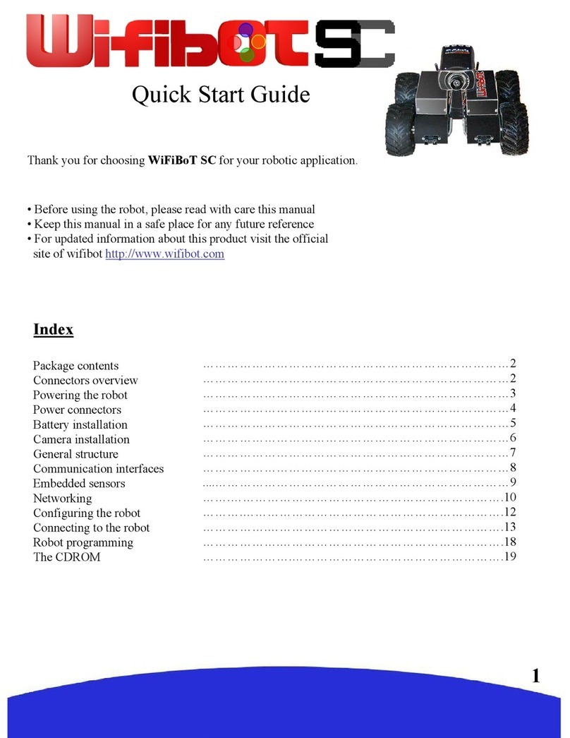
Quick Start Guide
Thank you for choosing the Wifibot Lab platform for your robotic
application.
• Before using the platform, please read with care this manual
• Keep this manual in a safe place for any future reference
• For updated information about this product visit the official
site of wifibot http://www.wifibot.com
Index
Package contents
.....…………………………………………………………………
2
Package contents
Quick start
Platform overview
Platform interfaces and charging
Computer and camera
System Architecture
Simple GUI
RTMIX multi-robot interface
Cameras
Connecting to the robot
Networking
Network configuration
Remote access
File transfer
Communication protocols
The CDROM
The standard CPU
1
.....…………………………………………………………………
2
.....…………………………………………………………………2
.....…………………………………………………………………2
…….………………………………………………………3-4-5
......………………………………………………………………6-7
.........………………………………………………………………8
..... …………………………………………………..…………9-10
...... ……………………………………………………...……11-14
.......………………………………………...…………………15-
16
............………………………………………………...………17-18
....…….……………………………………………………….19-20
....…….……………………………………………………….21-24
…………….………………………………………………….25-26
……………….……………………………………………….27-28
……………….……………………………………………….29-31
.... ……………….……………………………………………….32
.... ……………….……………………………………………….33

Package contents
Make sure to be in possession of all the
articles mentioned below. If any of them
should be missing, contact your reseller
as soon as possible.
Platform + SBC CPU
Pan & Tilt IP camera or Web Cam
Battery charger
Wifibot CDROM
Camera CD-ROM and documentation
1x charging cable
1x RJ45 cable for the IP camera
4 wheels and a screw driver
Platform overview
Antenna
connector
Aluminium support
Quick start
1- Install the RTMIX multi-
robot interface or
Simple GUI (see page 8).
2- Switch ON the robot or robots.
3- Set you IP settings (see page 12) for example:
192.168.1.25 mask 255.255.255.0
4- Connect to the robots’ ad-hoc network
(see page 13)
5- Launch GUI for controlling the robot
IR Sensors
2
Charging
connector
Power
ON/OFF
POWER 5V & 9.6v
connector
Fuse

Platform interfaces
The 5V,GND and 9.6V power output:
A 5V output, GND and a 9.6V filtered battery
output are accessible at a female DSUB-9
connector located at the rear of the robot. Pin 1-
2 are 9.6V, pin 4-5 are 5V and 6-7-8-9 are GND
output respectively. The 5V output can’t give
more than 4A and a maximum of 6A is
recommended too for the 9.6V output. An
incorrect use of this connector beyond those
values (short circuit or other) can provoke a
malfunction of the platform or of the DC/DC
converter and even damage it.
3
The charging connector:
This connector located on the left at the rear
of the robot, presents directly the + and – of
the platform batteries. When charging the
platform make sure the power switch is OFF
as it drives a relay for connecting the
connector to the batteries. If you want to
power the robot externally with a protected
power supply without his battery, just take off
the fuse.

The ON/OFF switch:
The platform is switched ON and OFF by the interruptor
located on the right at the back of the platform.
Interface connector:
This DSUB-9 male front connector presents a
mix of input-output signals. The pinout is the
following: (ADC are from 0 to 3.3v tolerant)
1- 5V 5- extra ADC
2- ADC IR Sharp Left 6- SDA (I2C)
3- ADC IR Sharp2 Right 7-8- GND
4- extra ADC 9- SCL (I2C)
The Fuse:
The 10 Amp fuse is located on the right at the back of the
platform.
4
The antenna connector:
This is the wi-fi antenna connector. Screw the
antenna carefully on the connector till the end.

Charging the robot:
A battery charger is included with the platform.
First make sure the platform and the charger are
OFF, then connect the plugs of the charging
cable and finally switch the charger ON and set
the charging current.
Caution:
Charge the robot at 2.5A on regular use.
To charge the robot, switch of f the power, plug the charger, push once the red button and when the
5
red light is blinking fast, tune the potentiometer to the desired Amp, the charger will stop charging
automatically.
The selector permit you to view battery voltage, charging Amp’s, and mA/ hour injected in the
batteries.
Never discharge deeply the robot (around Ov).
When the robot is completely discharged, you will need some time to launch 2 times the charger, he
will first charge the battery for 15 minutes and stop charging and you need then to relaunch the
charger again.
Charge the robot on a open area away from inflammable objects.
Do not let the battery without charging for more then 4-6 months, if so they can become dangerous.

Computer and camera installation
The platform is sold with an Pan & Tilt IP camera or webcam and an embedded computer which
model can vary depending of the version. Those are independent elements from the platform which
can be replaced by any other model. For more information about your particular camera and
embedded computer please refer to their respective manuals included in the CD ROM of the robot.
The top aluminium support witch is already mounted on the platform, has been thought for the
fixation of those and other user components.
Their installation takes place as follows:
The upper aluminium
support can be Unscrew
:
The embedded
computer is fixed on
the down part of the
support :
6

The power cable of the computer
is connected to the appropriate
connector:
The Control Command USB
connector is connected to the
computer.
7
Screw back the aluminium
support on top of the platform and
screw the IP camera on top of the
support.

System architecture:
This architecture is composed by 2 Parts : The high level composed by the sensors and the CPU (or
other custom devices), and the low level composed by a ICD2 capable DSPIC motor board controller.
An I2C to USB adapter is the link between the CPU and the low level.
Once plugged, Linux or windows see the I2C bus as a serial port. So to control the wheels or receive
sensors data, you need to send or receive RS232 frame. The protocol is explained at the end of this
manual. A simple TCP/IP gateway is provided with source code to see how it is simple to control the
robot using WIFI.
Platform + Sensors
CPU + Antenna
USB / SATA / RS232 / CF / IDE / GPIO
/ VGA / SOUND / Mini-Pci /
WIFIBOT
TCP/IP
Server
WIFI remote clients
High Level
8
Robot Platform + battery
+ DSPIC Motor Control
+ Encoders
USB -> I2C
Module
DSPIC Motor Board
Motor + Hall Coders
High Level
Low Level

The control software:
The control software can be found in the CDROM in
..\Software\control software\
• Install if necessary the Video Decoder
present in the same folder.
• Launch the WifibotGUI program.
• Click on Robot then Settings. The Robot
Settings window appears.
• Set the Control Server IP and the Control
Server Port which by default is 15020.
• Set the Camera IP and the Camera Port
which for the image is by default 80.
• Select the proper Camera Type.
If the camera type is not present use Firefox
or Internet explorer at port
8080
to view
Input Selections
(control panel for
calibrating the
joystick)
Video selections:
Allows to configure
and control some
options of the
camera.
Speed View: Plots in
real time the speed
signal from the code
wheels.
Motor Control ON:
Activates the speed
control, Input_Left
and Input_Right set on
the dialog will be
applied.
Motor Control OFF:
Deactivates the speed
control.
The control software (TCP)
Simple GUI:
or Internet explorer at port
8080
to view
the image.
• Click on Video, then select VideoOn. The
image from the camera will appear.
• Click on Robot then Connect.
• Click on Input then select Joystick or
Virtual_joy. The robot can now be operated.
The menu options:
Settings: IP settings of
the Control Server and
the Camera.
Connect: Starts the
communication with
the Control Server.
Disconnect: Stops the
communication with
the Control Server.
9
Reboot: Reboots
the robot’s CPU if
available.
Pan-Tilt camera control:
The red button takes the
camera to the default position.
You can click on the image
too for moving the camera.
Current input: shows the
current input or allows to set it
manually with keyboard.
Sensor feedback: shows the
data retrieved from the range
sensors, the battery level and
the speed of the robot in tics.

Ping Robot
Settings menu
Set IP & port of robot
IP & port camera
The control software (TCP)
Simple GUI:
Robot Type
Set robot type
1 WIFIBOT Lab
2 Emaxx 4wd
3 WIFIBOT SC/4G
10

RTMIX multi-robot interface:
Installation:
1- Unpack the zip file.
2- Double-click on Setup.
3- Unselect from the program list those you may already have
installed on your computer.
4- Click on the « install » button.
5- When asked to reboot your computer always say « no ».
6- Once installation is done, create a folder « rtmix » in the web
shared folder of the web server installed on your computer.
If you have followed the standard installation this would be
« C:/wamp/www/ »
10- Copy the containt of «C:/Program Files/RTMIX/monsite/»
into the «rtmix» folder you just created, ex:«C:/wamp/www/rtmix/»
11- Reboot your computer.
11

Features:
- The RTMIX multi-robot interface allows the user to control a team of up to four robots.
- The interface is best viewed with a 1024x768 resolution.
- Platform related controls are located on the left while visual related ones are located on the right.
- Before operation the user has to make sure all IP addresses and ports are correctly set.
- Selected robots can be controlled using the virtual joystick, a joystick or a wiimote, selecting more
than one robot at a time will have as a result having all of them receiving the same command.
- Cameras can be selected individually or blended in one image with RTMIX. Preset mixing layouts can
be selected and new ones added thanks to the “video source configuration” webpage.
- Certain functionalities need a reference which can be selected with a menu located just under the Mesh
and Map buttons.
- Certain types of supported cameras have incorporated relays which are set with the I/O checkbox.
- The “base” can be either an external gateway or the control computer itself (check “virtual” for this).
- The Map button needs to have an active internet connection and will show the robot’s and the base
position on a Google Maps webpage provided those are equipped with a GPS.
Preset video
mixing selection
Input
channel port
Output
channel port Video
window
Google
maps
Mesh
topology
graph
Configuration
port
12
Signal to
Noise Ratio
(Linux only)
Speed of the
robot’s mass
center
Battery
level
Robot
Selection
Camera
selection
Reference for
SNR and MAP
Robot IP
Not
implemented
Current video
selection
configuration
Camera type
selection
Controls for a
future charging
station
Camera IP
and port
Virtual
joystick
Camera relay
control
Check
« virtual »
when localhost
is the base

The input menu allows to
choose between four
modes of controlling the
robots. Those are:
- mouse (virtual joystick)
- joystick
- wiimote
- autojump (virtual joystick)
This is a mode where the robot
advances a certain distance with
a set speed and radius.
The markers menu allows for
now only to take snapshots of
the current video window and
to place a marker on the map at
the location it was taken. The
Program menu:
13
The view menu allows to
choose between two modes of
presentation:
- Normal view (default)
- Fullscreen view
This is a mode where the video
windows covers the whole screen.
It is particularly useful when using
configuration webpages or driving
the robots.
the location it was taken. The
snapshot can then be seen by
clicking on the marker.

Configuration:
The configuration webpage is accessible clicking on the
“video source configuration” button when RTMIX is selected.
The video mixing capabilities were originally designed to be
embedded in larger robots and controlled remotely. They were
only later adapted to the robolab system, this is the reason why
some options such as the analog cameras are not applicable.
To create a custom layout to be added to the interface menu do
the following:
- Select the cameras and sensors to be displayed.
- Drag the cameras and the sensors at the desired location.
- Set the size, opacity and z-order of the different cameras.
- Press the save button and introduce a name.
Video windows can be
dragged around in order
to precisely position them
on the screen
8x analog cameras
(not used with u-troopers)
Not
used
14
Scroll bar setting
the size of the
selected video
window
Sensor input
enable/disable
Reset Save
config
Scroll bar setting
the transparency
of the selected
video window Not
used
4x network cameras
z-order

Camera Type and software clients
compatibility:
15

Web Cam Server web client:
Windows WIA SERVER: http://192.168.0.XXX:8080
16
Linux MJPEG-STREAMER: http://192.168.1.XXX:8080

Connecting to the robot:
Configuring your ethernet/wireless adapter:
By default, the robot has been pre-configured with
certain IP addresses. Before connecting to the robot
you may need to adjust the IP settings of the network
adapter of your computer. Make sure all the devices
in a same network having to communicate with the
robot have the same class of address.
To adjust the TCP/IP settings of the network adapter:
1- Right-click on My Network Places in the Start
menu, then select Properties from the pop-up menu.
The Network and Dial-up Connections window
appears.(Fig1)
2 - Create a network bridge between your interfaces
or else disable all the network adapters except the
one you want to use for connecting to the robot
(Ethernet or Wi-Fi). Right-click the network adapter,
then select Properties from the pop-up menu. (in
Fig1)
Fig 1
Fig 2
3 - Double-click the Internet Protocol (TCP/IP)
item to display the Internet Protocol (TCP/IP)
Properties window. (in Fig2)
4 - Check the Use the following IP address option,
then enter the IP address for the network adapter. Set
IP address depending on the case : (in Fig3)
If you are connecting to a robot under Linux or
Windows with a cable directly to his Ethernet port,
then enter 192.168.0.x on your PC (x can be any
number between 1 and 254 except 250 and those
used by the CPU and the camera of the robot).
For example, a Wifibot Serial Number:
LABYYYXXX will have as IP for the CPU
192.168.0.XXX and 192.168.0.XXX:8080 for the
camera if webcam, 192.168.0.20:80 if IP camera.
Set the Subnet Mask to 255.255.255.0 and leave
Default gateway and DNS empty.
If you are connecting wirelessly to a robot:
Under windows because we bridge the wired
and the wireless interface, the IP are the same
as previous wired mode.
Under Linux we are on 192.168.1.XXX.
We NAT the eth0 to the ath0.
For example, a Wifibot Serial Number:
LABYYYXXX will have as IP
192.168.1.XXX, and 192.168.1.XXX:8080 for
the camera IP or webcam.
Set the Subnet Mask to 255.255.255.0
5 - Click OK when finished.
Fig 3
17

Connecting your wireless adapter to the robot:
Once you have adjusted the TCP/IP settings, if you
are using a cable and providing the robot is switched
ON then you are already connected but if you are
connecting wirelessly you have to make sure your
wireless adapter is connected to the robot and not to
something else. This can be done through windows
or using the software provided with your adapter.
To connect your wireless adapter to the robot using
windows, follow these steps:
• Switch ON the robot and wait a few seconds.
• In the Network and Dial-up Connections
window,right-click on the wireless network
adapter,then select Properties in the pop-up
menu. The Wireless Network Connection
Properties window appears.(Fig1)
• Click the Wireless Networks tab. A list of
wireless access points appears in the
Available networks
box. (in
Fig1
)
Fig 1
Fig 2
box. (in
)
• If the wifibot network is not listed in the
Available networks, then click Refresh till
it is. (in Fig1)
• Check the Use Windows to configure my
wireless network settings option.(in Fig1)
• Click OK when finished.
• Right-click on the wireless network adapter
again, then select View Available Wireless
Networks from the pop-up menu (in Fig2).
The Connect to Wireless Network dialog
box opens with a list of available networks in
the Available networks box. (in Fig3)
• Select the wifibot network from the list, then
check Allow me to connect to the selected
wireless network, even though it is not
secure option. (in Fig3)
• Click Connect (in Fig3), a pop-up window at
the bottom of the screen should appear
indicating you are connected. (in Fig4)
Fig 3
Fig 4
18

Networking
Network architecture:
In the Wifibot Lab the embedded CPU works
as a gateway between the internal wired
LAN and the external wifi WLAN. The
CPU has at least one ethernet card and one
wireless card that form two separate
networks (LAN/WLAN).The LAN and the
WLAN should have in general a different
address class and therefore data needs to be
routed between them. Depending if you have
chosen a robot under Windows or Linux the
problem of connecting the two networks has
been solved differently. Under Windows this
has been done by configuring a bridge
between the network interfaces, by doing so
the robot’s CPU appears to have a unique
network interface and uses one single IP
address. Under Linux, the interconnection is
done through Dynamic NAT (Network
Address Translation) and the CPU uses two
different IP
adresses
, one for the internal
Fig 1
different IP
adresses
, one for the internal
LAN and one for the WLAN. In both cases,
all local components of the robots such the
IP camera will have their own IP address
within the LAN, but when it comes to
accessing them from the WLAN the method
will differ. Under Windows as there is in
practice no distinction between the WLAN
and the LAN, every internal component will
be reached using its own IP address (see
Fig1). Under Linux, only the robot’s CPU
WLAN IP address can be seen and any
internal network element will have to be
reached using this single IP. In order to be
able to access the separate devices using a
single IP, we will need to assign to each of
them a separate port (see Fig2). This will
require to configure the CPU with the proper
routing table.
Fig 2
19

WLAN modes:
Let’s have here a quick overview of the different
modes Wi-Fi adapters can be configured :
-Infrastructure Master (Access Point)
-Infrastructure Managed (Adapter/Bridge)
-Ad-hoc without routing algorithm
-Ad-hoc with the OLSR routing algorithm
(Mesh Networking)
In infrastructure mode we have a master/slave
structure where all the data is centralized in one
device called access point (server/master) to which
different adapters (clients/slaves/managed) connect.
A client cannot talk directly to another but has to
pass by the access point which will forward the data
to the destination. Several access points can be
connected together with cables extending in this way
the zone covered by the wireless network. This is the
most common setup for a Wi-Fi network (see Fig1).
In ad
-
hoc mode we do not have any central
Fig 1
In ad
-
hoc mode we do not have any central
management, each client can talk directly to the
other. This mode works fine for networks with few
elements. Without any routing algorithm, each
element needs to have a direct radio link with the
others in order to communicate, no data will be
forwarded (see Fig2). If a routing algorithm such as
OLSR or BATMAN is added, you obtain a self-
organizing mesh network in which message
forwarding is possible wirelessly between different
nodes, connecting in this way devices which are not
within direct radio range (see Fig3). This allows to
extend the zone covered without the need of any
cable.The network is completely dynamic, routing
tables are rewritten automatically and dynamically
as the network changes. If a new OLSR or
BATMAN enabled device appears, it will be
automatically detected and merged to the routing
tables of each node. This is especially useful for
mobile networks that can change over time like for
example in a multi-robot application. 20
Fig 2
Fig 3
Table of contents
Other Wifibot Robotics manuals
Popular Robotics manuals by other brands
Epson
Epson LS-B Series Maintenance manual
Omron
Omron TM5 Regular Payload Series Hardware installation manual
Paddle Palace
Paddle Palace A32W PRO ROBOT user manual

OTTO MOTORS
OTTO MOTORS 1500 V2 Operation and maintenance manual
Mitsubishi Electric
Mitsubishi Electric CR800 Series Ethernet Function Instruction Manual

Barrett
Barrett burt RESEARCH installation guide
