WifiTrax Model Science WFG-80 User manual

WFG-80 8-Way Lighting/General Controller Operating Manual
P a g e | 1 WifiTrax Model Science
www.wifitrax.com
WFG-80 8-Way Lighting/General Controller
Operating Manual
This document is online at http://www.wifitrax.com/manuals/WFG-80/WFG-80-Manual.pdf.
Please see our website for information on our limited warranty.
WifiTrax Model Science
www.wifitrax.com
Version 1.0 March 17, 2021
© WifiTrax Model Science 2021 All Rights Reserved
This product is not a toy. Keep away from children. It is not suitable for use by persons under 14 years of age.
Warning: This product contains chemicals known to the state of California to cause cancer, birth defects or
other reproductive harm.

WFG-80 8-Way Lighting/General Controller Operating Manual
P a g e | 2 WifiTrax Model Science
www.wifitrax.com
Version History
Version
Changes
1.0
Initial Release
Applicable Firmware Version
This manual applies to WFG-80 Firmware Versions 2.0.0 or later.
Table of Contents
Applicable Firmware Version..................................................................................................................2
Table of Figures.......................................................................................................................................4
What does WFG-80 8-Way Lighting/General Controller do? .................................................................5
Let’s get Started!.....................................................................................................................................6
Connecting your new WFG-80 Cab Bus Wi-Fi Interface .....................................................................6
Installation Instructions ......................................................................................................................8
Testing and Configuring your WFG-80................................................................................................9
Connecting using an Apple IOS Phone or Tablet ............................................................................9
Connecting using Android.............................................................................................................10
Connecting using Windows...........................................................................................................10
Testing using the WFG-80 Web pages ..........................................................................................10
Operational Options for the WFG-80....................................................................................................11
Some Background .............................................................................................................................11
Use WFG-80 Web Pages on a Phone, Tablet or Computer...............................................................13
Use WFD-60 as a WiThrottle Protocol Gateway...............................................................................14
Use WFD-60 as a DCC Gateway ........................................................................................................15
Use the Tower Operator App on Windows or Android ....................................................................16
The WFG-80 Web Pages in Detail .........................................................................................................16
Main Menu Page...............................................................................................................................17
Settings Page.....................................................................................................................................17
Home Net Page .................................................................................................................................19
Light Channels Page..........................................................................................................................19
WFG-80 Light Channel Edit Page ......................................................................................................20
Dimmer Channels Page.....................................................................................................................21
Dimmer Edit Page .............................................................................................................................21

WFG-80 8-Way Lighting/General Controller Operating Manual
P a g e | 3 WifiTrax Model Science
www.wifitrax.com
Reset Page.........................................................................................................................................22
Tips to Manage your Home Network....................................................................................................23
Connection to your Home Router.....................................................................................................23
Home Net IP Address Assignment ....................................................................................................23
Reserving a Fixed IP Address.............................................................................................................25
More Information .................................................................................................................................26
FCC Information....................................................................................................................................27
EU Declaration of Conformity...............................................................................................................28

WFG-80 8-Way Lighting/General Controller Operating Manual
P a g e | 4 WifiTrax Model Science
www.wifitrax.com
Table of Figures
Figure 1 Connections and switches on the WFG-80 ...............................................................................5
Figure 2 Connections for Light Emitting Diodes (LEDs)...........................................................................6
Figure 3 Connection Diagram for Grain-of-Wheat Lamps ......................................................................7
Figure 4 Connecting two-lamp signals with a common lead..................................................................8
Figure 5 Connecting three-lamp signals with a common lead................................................................8
Figure 6 Mounting Suggestion................................................................................................................9
Figure 7 WFG-80 Web Pages - Main Menu...........................................................................................10
Figure 8 WFG-80 Web Pages –Light Channel List ................................................................................11
Figure 9 The Dimmer Channels List ......................................................................................................11
Figure 10 Options for control of lights using the WFG-80....................................................................12
Figure 11 Control of WFG-80 using only its Web Pages .......................................................................13
Figure 12 Controlling the WFG-80 via a WFD-60 and WiThrottle Protocol Devices.............................14
Figure 13 Controlling the WFG-80 using DCC such as an NCE Command Station/Booster..................15
Figure 14 Using the WifiTrax Tower Operator App to control WFG-80 with lights in buildings and
signals....................................................................................................................................................16
Figure 15 WFG-80 Main Menu page.....................................................................................................17
Figure 16 WFG-80 Settings page...........................................................................................................18
Figure 17 WFG-80 Home Net page.......................................................................................................19
Figure 18 WFG-80 Light Channels page ................................................................................................20
Figure 19 WFG-80 Light Channel Edit page ..........................................................................................21
Figure 20 WFG-80 Dimmer Channels page...........................................................................................21
Figure 21 Dimmer Channel Edit page ...................................................................................................22
Figure 22 The Factory Reset page.........................................................................................................22
Figure 23 Using ipconfig to find your computer's IP address and default gateway .............................23
Figure 24 Access your router by using the IP Address of your default gateway in a browser .............24
Figure 25 A typical router admin page..................................................................................................24
Figure 26 Typical "Attached Devices" page of a router ........................................................................25
Figure 27 Use the IP Address to open the main menu web page.........................................................25
Figure 28 An IP Address reservation table in a router..........................................................................26
Figure 29 Adding an address reservation .............................................................................................26
Figure 30 Identifying Illustration for WifiTrax Model WFG-80 EU Declaration of Conformity.............28

WFG-80 8-Way Lighting/General Controller Operating Manual
P a g e | 5 WifiTrax Model Science
www.wifitrax.com
What does WFG-80 8-Way Lighting/General Controller do?
The WFG-80 allows you to control eight LED, low voltage filament lamps or other low-current
devices via Wi-Fi.
•You can control lights using a smart phone, tablet or computer, provided it has Wi-Fi
capability, using a web browser such as Apple Safari, Google Chrome or Microsoft Edge.
•You can use WifiTrax Tower Operator to build a schematic control panel that can include
lights and signals implemented with the WFG-80 as well as switch machines and power
districts implemented with other WifiTrax modules.
•You can use a WifiTrax WFG-80 WiThrottle/DCC gateway to control lights connected to one
or more WFG-80 using WiThrottle
1
on Apple, Engine Driver
2
on Android, or a special-purpose
hand-held throttle such as TCS UWT-100
3
designed to control trains using the Hoffman
WiThrottle Protocol
4
. The lights appear as accessories within those apps and devices.
•Four hand-held devices at a time can join the WFG-80 Wi-Fi Access Point, but you can
increase this limit using “home-net” mode as described later in this manual.
You don’t need to install JMRI to use the WFG-80
Bank 2
Bank 1
J6 Bank 2 Channel
Mode Links
J4 Bank 1 Channel
Mode Links
Power
Firmware
Upgrade
1 2 3 4 5 6 7 8
1 2 3 4 5 6 7 8
Figure 1 Connections and switches on the WFG-80
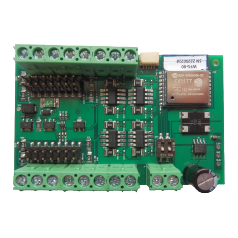
Figure 1 shows the WFG-80 module with its connectors labelled. There are two banks of screw connectors,
labelled Bank 1 and Bank 2, that each have four pairs of outputs. Each can be connected to an LED, filament
1
WiThrottle is an app running on Apple IOS written by Brett Hoffman. It is available as a free version
(WiThrottle Lite) or a better moderately-priced paid version, both available on the Apple App Store.
2
Engine Driver is an app running on Android, written by M. Steve Todd. It is available free on the Google Play
Store.
3
UWT-100 is a hand-held controller using the WiThrottle Protocol available from Train Control systems (TCS).
4
WiThrottle Protocol is a network protocol invented by Brett Hoffman and used in WiThrottle, Engine Driver,
JMRI and the TCS UWT-100. It has become a de-facto industry standard.

WFG-80 8-Way Lighting/General Controller Operating Manual
P a g e | 6 WifiTrax Model Science
www.wifitrax.com
lamp or some other low current device. Each of these outputs are capable of driving about 70 mA
simultaneously with the other channels. This is easily enough to drive light emitting diodes (LEDs) and will also
drive small filament lamps. Each pair of outputs has a plus and minus label and when LEDs are connected, the
anode of each LED must be connected to the plus terminal as shown in Figure 2.
All the positive terminals of each bank are, in fact, connected together and provide pulse width modulated
voltage that allows that bank to have controlled brightness. The negative terminals are switched by the device
to conduct or not, so as to turn on or off the individual light source.
Power is supplied via the screw terminals labelled Power in Figure 1 which may be connected with either
polarity. A DCC signal may also be used, simply as a power source, but the unit is not designed to work with
50Hz AC.
Each bank has a collection of links that are used to switch one of two resistors to appear in series with each
output. This is to allow either filament lamps or LEDs to be accommodated. LEDs require a series resistor to
limit the current and, with the link for a channel removed, the series resistance is 1000 ohms (1 KΩ). Either
zero or 475 ohms can be placed in series by placing or removing a link as described in Table 1.
A JST connector at the top right in Figure 1 allows firmware upgrade using the WifiTrax FWA-11 together with
the WifiTrax Workshop application running on a Windows computer.
Let’s get Started!
Connecting your new WFG-80 Cab Bus Wi-Fi Interface
Links
removed
for LEDs
D1 D2 D3 D4
D8D7D6D5
5- 5+ 6- 6+ 7+ 8+7- 8-
Bank 2 Outputs
Cathode Anode
Cathode
Anode
Switches Always in
ON position as
shown
Diodes must be connected
The correct way around
As shown.
Diodes must be connected
The correct way around
As shown.
1+ 1- 2+ 2- 3- 4-3+ 4+
2+ 2- 3+ 3- 4+ 4-
Bank 1 Outputs
DC Power
+-
Figure 2 Connections for Light Emitting Diodes (LEDs)

WFG-80 8-Way Lighting/General Controller Operating Manual
P a g e | 7 WifiTrax Model Science
www.wifitrax.com
Links
added in
positions
shown for
bulbs
5- 5+ 6- 6+ 7+ 8+7- 8-
Bank 2 Outputs
Switches Always in
ON position as
shown
Bulbs may be connected
either way around.
1+ 1- 2+ 2- 3- 4-3+ 4+
2+ 2- 3+ 3- 4+ 4-
Bank 1 Outputs
DC Power
+-
Lamp1 Lamp2 Lamp3 Lamp4
Lamp5 Lamp6 Lamp7 Lamp8
Figure 3 Connection Diagram for Grain-of-Wheat Lamps
Connect your LEDs or filament lamps as in Figure 2 or Figure 3. The only difference is that polarity
must be observed with LEDs. If you connect an LED around the wrong way, it will not be damaged
but will not light. Filament lamps may be connected either way. Take care to remove all links if you
are using LEDs. This is because a series resistor of around 1000 ohm (1KΩ) must be included to limit
the LED current. Failure to provide this series resistance will destroy the LED. If you want the LED
really bright, you can use a link to set the resistance to 475 ohms, but this will likely shorten the life
of the LED. For filament lamps such as “Grain of Wheat” (GOW) lamps, no series resistance is
needed. The WFG-80 will not drive lamps requiring more than around 90mA, so only GOW lamps are
supported and these should preferably be 9V lamps or less to get good brightness.
Link
Linked
Open
Remarks
J4 1
OUT 1 Direct
Filament Lamp
J4 2
OUT 1 475 Ohm
LED Bright
Leave open for 1K
J4 3
OUT 2 Direct
Filament Lamp
J4 4
OUT 2 475 Ohm
LED Bright
Leave open for 1K
J4 5
OUT 3 Direct
Filament Lamp
J4 6
OUT 3 475 Ohm
LED Bright
Leave open for 1K
J4 7
OUT 4 Direct
Filament Lamp
J4 8
OUT 4 475 Ohm
LED Bright
Leave open for 1K
J6 1
OUT 8 Direct
Filament Lamp
J6 2
OUT 8 475 Ohm
LED Bright
Leave open for 1K
J6 3
OUT 7 Direct
Filament Lamp
J6 4
OUT 7 475 Ohm
LED Bright
Leave open for 1K
J6 5
OUT 6 Direct
Filament Lamp
J6 6
OUT 6 475 Ohm
LED Bright
Leave open for 1K
J6 7
OUT 5 Direct
Filament Lamp
J6 8
OUT 5 475 Ohm
LED Bright
Leave open for 1K
Table 1 Link option settings
Sometimes you may wish to connect a signal that has two lamps but only three wires; or perhaps a
signal that has 3 lamps but only four wires. This means that one side of each of the lamps is

WFG-80 8-Way Lighting/General Controller Operating Manual
P a g e | 8 WifiTrax Model Science
www.wifitrax.com
connected together and is a common lead. In this case refer to Figure 4 and Figure 5. Here the
positive side is common and only one positive connection is required for each group of lamps.
Links added in positions
shown for bulbs.
For LED Signals, remove
Links and connect
cathodes to negative
sides.
5- 5+ 6- 6+ 7+ 8+7- 8-
Bank 2 Outputs
Switches Always in
ON position as
shown
Always connect common wires
to positive (+) termals
1+ 1- 2+ 2- 3- 4-3+ 4+
2+ 2- 3+ 3- 4+ 4-
Bank 1 Outputs
DC Power
+-
Lamp1 Lamp2 Lamp3 Lamp4
Lamp 6
Lamp 5 Lamp 8
Lamp 7
RED
Common
Wire Red
Wire Green
Wire
RED
Common
Wire Red
Wire Green
Wire
GREEN
RED
Common
Wire
Red
Wire Green
Wire
GREEN
RED
Common
Wire
Red
Wire Green
Wire
Signal 3
Signal 4
Figure 4 Connecting two-lamp signals with a common lead
Links added in positions
shown for bulbs.
For LED Signals, remove
Links and connect
cathodes to negative
sides.
5- 5+ 6- 6+ 7+ 8+7- 8-
Bank 2 Outputs
Switches Always in
ON position as
shown
Always connect common wires
to positive (+) termals
1+ 1- 2+ 2- 3- 4-3+ 4+
2+ 2- 3+ 3- 4+ 4-
Bank 1 Outputs
DC Power
+-
Lamp1 Lamp2 Lamp3
RED AMBER
Common
Wire Red
Wire Yellow
Wire
GREEN
Green
Wire
Signal 1
Lamp1
Lamp2
Lamp3
GREEN
AMBER
Common
Wire
Red
Wire Yellow
Wire
RED
Green
Wire
Signal 2
You can use channels 4 and 8
for simple lights, a 2-light signal
or combine with spare outputs
on another unit for another 3-
light signal.
Figure 5 Connecting three-lamp signals with a common lead
Installation Instructions
(1) First determine what kind of lights you wish to control. WFG-80 will control two basic types: Light
Emitting Diodes (LEDs) and low power filament lamps such as “Grain of Wheat Bulbs”. You are

WFG-80 8-Way Lighting/General Controller Operating Manual
P a g e | 9 WifiTrax Model Science
www.wifitrax.com
advised to use GOWS rated around 9 Volts or less. Higher voltage bulbs can be used but they will not
be very bright. You can make the lights brighter by using a higher power supply voltage such as 15
Volts instead of 12Volts. Also note that you can turn the dimmers to a higher setting using Tower
Operator or the WFG-80 Web pages.
You can mix LEDs and filament lamps on the same board but you must be careful to place the links
correctly. The links provide three options for each channel, Direct, “475 Ohm series resistor”or “1000
Ohm series resistor”. If you use LEDs you MUST use the 475 or 1000-Ohms option for those channels.
Direct mode will DESTROY LEDs. If you use filament lamps you need to use Direct mode for those
channels or the lamps will be very dim. Table 1 shows the link settings.
You can also combine channels to control features with multiple lights like signals. Tower Operator
allows you to assign channels to the signal device on the screen once it is physically connected.
(2) Wire the WFG-80 to your lights or signals according to Figure 2, Figure 3, Figure 4 or Figure 5. Be
sure to connect any common wires to the positive side of each of the eight channels.
(3) Note that each of the two banks can be dimmed independently through software using the WFG-80
Web Pages or the Tower Operator app.
(4) Note that the two DIP switches must be always in the on position. These are only changed to off for
firmware update.
(5) Connect power to your unit at TRKA and TRKB as shown in Figure 2 through Figure 5. It does not
matter which way round you connect the power. You can also use DCC track power but NOT AC. The
power should be between 12 and 18 volts.
Board
Components On
WFG-80
WFG-80 PCB M3 Screw
Aluminum Spacer
M3 Nut M3 Washer
Figure 6 Mounting Suggestion
(6) Mount the unit using the four M3 metric screws, nuts and spacers provided. Mount the unit on a
suitable piece of board, either your baseboard (top or bottom) or a separate board perhaps at the
front of your model railroad. The component side of the module should face away from the board as
in Figure 6. It is a good idea to mount it somewhere that is easily accessible. If you omit the spacers
be sure not to tighten screws so that the unit bends. Take care that no part of the unit touches any
metal as this may cause a short circuit and result in permanent damage. Do not mechanically stress or
bend the module as this may cause damage. Take care to ensure that there is adequate ventilation
to avoid overheating.
(7) CHECK YOUR WIRING! Turn on the power. You may test the unit using WFG-80 Web Pages described
in the next section. Later you may decide to use the Tower Operator App. Refer to the Tower
Operator Quick Start, or Full Help Pages for instructions on setting up a schematic control panel on
your Windows or Android computer or tablet.
Testing and Configuring your WFG-80
You can test and configure the WFG-80 using its web pages which are accessible from any browser on Apple
IOS, Android or Windows. For example, you can use Apple Safari on an iPad, Google Chrome on an Android or
Microsoft Edge on Windows.
Connecting using an Apple IOS Phone or Tablet
(1) Tap the Settings icon on your iPhone or iPad

WFG-80 8-Way Lighting/General Controller Operating Manual
P a g e | 10 WifiTrax Model Science
www.wifitrax.com
(2) Tap Wi-Fi on the left-hand menu. Under Other Networks on the right, the list should include one like
wftrx_WFG80_1_XXXXXXXX_7, where XXXXXXXX is the serial number of your unit that appears on its label.
Tap that Wi-Fi Network and wait for a green check mark that shows it has connected. You must always
connect to this Network to access the WFG-80 web pages unless you operate in home-net mode.
Connecting using Android
(1) Press the Home button and tap the Settings icon:
(2) Tap Connections, then Wi-Fi and select the module’s wftrx_WFG80_1_XXXXXXXX_7 network as
above. Wait for it to show that it has connected.
Connecting using Windows
On your Windows 10 desktop or laptop, click the networks icon in the system tray and select the module’s
network wftrx_WFG80_1_XXXXXXXX_7 as described above.
Testing using the WFG-80 Web pages
(1) Once you are connected to the module’s network, open a browser such as Safari, Chrome or Edge and
type the following in the URL bar followed by the Enter or Go key:
192.168.7.1
See Figure 7 which shows the IP Address 192.168.7.1 entered into the author’s Edge browser running on
Windows 10. This is the IP Address of the WFG-80 web pages when you are connected directly to its
wftrx_WFG80_1_XXXXXXXX_7 network. When operating like this, the WFG-80 controls all addresses on its
own little network. The IP address is the “raw” address of a website. Usually, people do not type an IP
address into a browser but browsers do support this. Remember You will not be able to access these
pages until you are connected to the module’s wftrx_WFG80_1_XXXXXXXX_7 network.
(2) You will see the Main Menu page as below:
Figure 7 WFG-80 Web Pages - Main Menu
(3) To test the lighting channels, click or tap the Light Channels option. You will see the screen in Figure 8.
The names of each channel default to the serial number plus the channel number as shown. You can
change these names later.

WFG-80 8-Way Lighting/General Controller Operating Manual
P a g e | 11 WifiTrax Model Science
www.wifitrax.com
Figure 8 WFG-80 Web Pages –Light Channel List
(4) Assuming your lights are connected properly, tapping the button in the State column will toggle
the light on and off.
(5) Use the Back hyperlink to return to the Main Menu page, then select Dimmer Channels. Here you can
adjust the brightness of each of two banks of four lights as in Figure 9.
Figure 9 The Dimmer Channels List
(6) You can also click on each entry in the lights or dimmers list to edit the names and DCC addresses. DCC
addresses are relevant if you use the WFD-60 WiThrottle/DCC gateway so your lights can appear as
accessories on your DCC system.
For full information on the WFG-80 Web Pages see the section “The WFG-80 Web Pages in Detail”.
Operational Options for the WFG-80
This section describes the options available for operating WFG-80 on your layout, that is to say, how
can you turn lights on or off during normal running of trains.
Some Background
The WFG-80 can be controlled in two ways (1) through its Web Pages and (2) through its WifiTrax
JSON interface. The JSON interface consist of a defined set of messages that can be sent to the

WFG-80 8-Way Lighting/General Controller Operating Manual
P a g e | 12 WifiTrax Model Science
www.wifitrax.com
module from the outside via its Wi-Fi network, using the HTTP protocol, to control it and obtain
information from it. All WifiTrax modules support a JSON interface with messages that are specific to
the particular module. We do not need to go into any more details about this interface except to say
that it is only used between WifiTrax modules and between WifiTrax apps and modules.
Many WifiTrax modules also support the WiThrottle Protocol which is a protocol invented by Brett
Hoffman for use with his WiThrottle app running on Apple IOS. It has become a de-facto industry
standard and is used by Java Model Railroad Interface (JMRI) to allow Wi-Fi throttles to control locos
and accessories via JMRI. Examples of such throttles are WiThrottle (by Brett Hoffman running on
Apple IOS), Engine Driver (by Steve Todd, running on Android) and TCS UWT-100. All of these can
work with JMRI, but several companies, including WifiTrax have built servers within modules that
can be put in the place of JMRI and support the same set of throttles. Examples are WifiTrax WFD-30
and WFD-31 and Digitrax LNWI.
WFG-80 does not support the WiThrottle Protocol directly since it cannot control locomotives and
probably no one would want to use a throttle just to control lights.
So, what ARE the options? Figure 10 shows all the options and interfaces. The next sections explains
each option in detail.
WifiTrax Tower Operator App Web Browser Web Browser
Figure 10 Options for control of lights using the WFG-80

WFG-80 8-Way Lighting/General Controller Operating Manual
P a g e | 13 WifiTrax Model Science
www.wifitrax.com
Use WFG-80 Web Pages on a Phone, Tablet or Computer
Web Browser
Figure 11 Control of WFG-80 using only its Web Pages
Figure 11 shows this simplest method of operation which is to simply connect a phone, tablet or
computer to the WFG-80’s Wi-Fi network wftrx_WFG80_1_XXXXXXXX_7 as described in the section
“Testing using the WFG-80 Web pages”, open a browser at the IP Address 192.168.7.1 and use the
web pages described in section “The WFG-80 Web Pages in Detail” to do all of the control you need.
This is OK if your tablet or computer does not need to do anything else on your layout. The problem
is that once it is connected to that network, it cannot be connected to anything else, so you cannot
use the same tablet/phone/computer to drive a locomotive using, say, the WFD-30 or WDMI-32, or
indeed to connect to JMRI. If you have some old phones around, you could dedicate one for this
purpose.
However, a much better way of using the web pages for WFG-80 control is to set the WFG-80 into
home-net mode. The way to do that is described in the section “Home Net Page”. Once in home-net
mode, the WFG-80 connects to your home Wi-Fi router as soon as it powers up and you can
communicate with its web pages and do other things on your home network as well such as control
locos. Using later versions of Android, you can use split screen with the browser in half of the screen
and a driving app such as Engine Driver in the other half.

WFG-80 8-Way Lighting/General Controller Operating Manual
P a g e | 14 WifiTrax Model Science
www.wifitrax.com
What if you have more than one WFG-80? Well, all browsers allow multiple tabs, so you can connect
one tab to each WFG-80. If you have other Wi-Fi Layout modules such as WFS-46 or WFS-86, you can
have a tab dedicated to those as well.
So, this is a simple way of controlling lights, turnouts and trains. There is a complication in that you
do need to know the IP address that your router assigns to each WifiTrax module. Once you know
these you can add the web pages for each module to your browser favourites and give them names.
A further issue is that the router might not always assign the same address to a module, but on most
routers, you can avoid this by reserving IP addresses for each module. Please see the section
“Reserving a Fixed IP Address” later in this manual.
Use WFD-60 as a WiThrottle Protocol Gateway
Web Browser
Figure 12 Controlling the WFG-80 via a WFD-60 and WiThrottle Protocol Devices
You can get much more versatile if you use the WFD-60 as in Figure 12. The WifiTrax WFD-60 acts as
a WiThrottle Protocol Gateway. This means that once you place it on your home net, it scans a
specified range of IP addresses on your home net looking for WifiTrax Modules such as WFG-80 (or
the WFS modules). Once it finds one, it determines the channels on it and exposes them as either
locomotives or accessories on a WiThrottle Protocol device connected to it.
You control the WFD-60 using its own Web Pages accessible either via a browser or through the
Engine Driver or WiThrottle (paid version) apps.
As an example, if you have two WFG-80s on your home net and a WFD-60, the WFD-60 will find the
WFG-80 modules and determine that each has 8 channels. When a WiThrottle Protocol device
connects to it, such as WiThrottle running on an iPad, it will provide the set of accessories to the
WiThrottle app on the iPad using the WiThrottle Protocol. This works with Android Engine Driver,
Apple WiThrottle and TCS UWT-100.
With this option then, everything is available through one WiThrottle Protocol Server (the WFD-60)
and up to six throttles can connect to it controlling lights and driving trains.

WFG-80 8-Way Lighting/General Controller Operating Manual
P a g e | 15 WifiTrax Model Science
www.wifitrax.com
Use WFD-60 as a DCC Gateway
Figure 13 Controlling the WFG-80 using DCC such as an NCE Command Station/Booster
The WifiTrax WFD-60 is also a DCC gateway in that it contains a DCC decoder that responds to any
DCC addresses found during the scan of the home net. Figure 13 shows this configuration.
For example, the WFG-80 implements 8 light control channels, each of which can be assigned a DCC
accessory address. As far as the module itself is concerned, this is not very relevant since the WFG-
80 does not contain a DCC decoder. However, when a WFG-60 finds it, the WFD-60 DCC gateway
acts as a proxy and decodes the DCC message, converts it into a WifiTrax JSON Interface message
and sends it to the WFG-60. Thus, one can use any DCC command station connected to the WFD-60
to control the channels on the WFG-80 as accessories.
If more than one WFG-80 exist on the home net, their channels must all have unique DCC addresses
assigned. Similarly, if you add other modules such as WFS-46/86, all must have unique DCC
addresses.
Taking this further, it is now possible to use a system such as JMRI through any supported DCC
command station, connected to a WFD-60 to control lights using WFG-80 or switch machines using
the WFS Switch Controller Series or indeed locomotives using the WDMI Wi-Fi/DCC series or the
WMR-10/WMH-20 Wifi Loco modules.

WFG-80 8-Way Lighting/General Controller Operating Manual
P a g e | 16 WifiTrax Model Science
www.wifitrax.com
Use the Tower Operator App on Windows or Android
WifiTrax Tower Operator App
Figure 14 Using the WifiTrax Tower Operator App to control WFG-80 with lights in buildings and signals
Tower Operator is a complex app, developed by WifiTrax and available free, that runs on Windows
10 or Android. This app allows you to scan your home network for controllers such as WFG-80. You
can then use it to create logical devices such as lights and signals whose control points are mapped
to channels on the WFG-80 controller.
For example, you could create four lights and two double-light signals. Then you would assign each
light to one channel on a WFG-80 and each signal to two of the remaining channels.
Having done this, you can create a map (schematic control panel), such as appears in dispatcher’s
train control panels, and add the lights and signals to it, together with a track plan. Of course, Tower
Operator also supports the WFS Switch Controller Series so you can create various kinds of switch
logical devices such as left and right turnouts, double slips etc. and integrate them all together on a
schematic panel for part or all of your layout.
The WFG-80 Web Pages in Detail
The WFG-80 web pages allow configuration and control of the module including overall settings,
home net, light channels and dimmer channels. Please remember that these web pages are entirely
generated within the module itself and so no internet access is needed to access them.
When the module is not in home net mode, i.e., as it is shipped or after a factory reset, the web
pages can be accessed by first connecting a computer or tablet to its Wi-Fi network
wftrx_WFG80_1_XXXXXXXX_7 (where XXXXXXXX is the module’s serial number), then using any
browser (Chrome, Safari, Edge, etc.) to access the URL 192.168.7.1. In this case the URL typed into
the browser is just the IP address of the module on its own network.

WFG-80 8-Way Lighting/General Controller Operating Manual
P a g e | 17 WifiTrax Model Science
www.wifitrax.com
When the module has been placed on a home net, the IP address will be assigned by the router and
you will need to type that IP address into the browser. See the section “Home Net IP Address
Assignment”.
Main Menu Page
When you access the address described above, you will be taken to the Main Menu web page as
shown in Figure 15.
Figure 15 WFG-80 Main Menu page
Settings Page
Access the Settings Page by tapping or clicking the Settings menu item on the Main Menu page.

WFG-80 8-Way Lighting/General Controller Operating Manual
P a g e | 18 WifiTrax Model Science
www.wifitrax.com
Figure 16 WFG-80 Settings page
The Settings page in Figure 16 has some lines of information and some items that can be changed.
The first line shows the current IP address of the module and in the example, it is the address that it
always takes on its own network. On the same line is the region code, either 1 for North America or
0 for the rest of the world. Following this, on the same line is the serial number.
The second line shows the firmware version followed by some debug information relating to
something called the “heap” formatted as: (Current heap space)/(Minimum recorded heap space).
Lastly on the second line is the number of restarts since a factory reset.
The third line shows the current name of the module which defaults to SN followed by the serial
number. You may change this to anything up to 10 characters without spaces.
The next line shows the Wi-Fi channel, defaulted to channel 1 on the 2.4GHz band. You can change
this to a value from 1 to 11 in North America or 1 to 13 in the rest of the world. This channel is only
applicable when the module is NOT in home-net mode. In home-net mode, the Wi-Fi channel is
determined by the router.
Lastly, there is an option to change the Net Number which defaults to 7. This is the number that
appears in the IP address as the third number, e.g., 192.168.NN.1, where NN is the net number.
Again, this is only applicable when the module is NOT in home-net mode since in home-net mode
the IP address is assigned by the router.
When any of these are changed, it is necessary to click on the Save button. If any of the settings are
invalid, none will be accepted. If all the settings are valid, they will be saved in Flash memory
permanently. A factory reset will restore default values.
Wi-Fi changes will not have any effect until the power is cycled.

WFG-80 8-Way Lighting/General Controller Operating Manual
P a g e | 19 WifiTrax Model Science
www.wifitrax.com
Home Net Page
The Home Met page in Figure 17 is accessed by tapping or clicking the Home Net item in the Main
Menu page.
Figure 17 WFG-80 Home Net page
The Home Net page is used to place the module on your Home Wi-Fi Network. Once this is done, you
can access the module without connecting to its own network, indeed its own network will no longer
be advertised. Once in home-net mode, each time on power-up, the module will attempt to connect
to the specified home network. After a certain period of time, if it fails, it will revert to its original
(direct i.e., non-home-net) mode and begin advertising its own wftrx_WFG80_1_XXXXXXXX_7
network again. Thus, if your home network is not accessible, you can always go back to accessing it
in direct mode.
To set the module into home-net mode you need your home network’s SSID and password, which
must be entered on this page, as in the example followed by clicking the Install button. You can
usually find your SSID and password on a card supplied by your internet service provider. Or, of
course, you may have changed it.
When the module goes into home-net mode it will restart and you will lose access to these web
pages. To display them again, use the IP address assigned by your router, see section “Home Net IP
Address Assignment”.
When the module is in home-net mode, you can also use this page to remove it from the home net
and go back to direct mode. The module will restart and you will lose access to these web pages. To
display them again use the IP address 192.168.7.1.
You can leave the Home Net page without changing anything by clicking Back.
Light Channels Page
Access the Light Channels Page by tapping or clicking the Light Channels menu item on the Main
Menu page.

WFG-80 8-Way Lighting/General Controller Operating Manual
P a g e | 20 WifiTrax Model Science
www.wifitrax.com
Figure 18 WFG-80 Light Channels page
This page, shown in Figure 18 lists all of the output channels of WFG-80 used to drive lights. Each
channel has a number from zero to seven, a name, a DCC address and a state column showing the
channels current state. The name and DCC address will be supplied to any WFD-60 gateway module
that discovers the WFG-80 module on the home net. The DCC address will determine the accessory
address for which a WFD-60 will accept a DCC Accessory Command on its DCC bus input.
The buttons in the right-hand column under the State heading can be used to toggle the output of
that channel between on and off.
The Save as Default button will cause the current states of all the channels to be saved into flash
memory to define the power-on default state.
Clicking or tapping on the hyperlinks for a given row in the Name column will open an edit page for
the channel represented by that row.
Click the Back hyperlink to return to the Main Menu page.
WFG-80 Light Channel Edit Page
This page, shown in Figure 19 allows editing of the name and DCC address for one of the light
channels. Click Save to cause the new values to take effect.
The name can be up to 31 characters long.
The DCC address can be up to 9999.
If any entry is invalid, none will be saved.
Other manuals for WFG-80
1
Table of contents
Other WifiTrax Model Science Controllers manuals