Stober CiA 402 User manual

CiA 402 Controller Based
Operation manual
ID 442454.0212/2015en

ID 442454.02 2WE KEEP THINGS MOVING
Table of contents
Operation manual CiA 402 Controller Based
Table of contents
1 General Information . . . . . . . . . . . . . . . . . . . . . . . . . . . . . . .. . . . .3
2 Basic information . . . . . . . . . . . . . . . . . . . . . . . . . . . . . . . . . .. . . . .8
3 Commissioning . . . . . . . . . . . . . . . . . . . . . . . . . . . . . . . . . . . .. . . .49
4 Object directory - References . . . . . . . . . . . . . . . . . . . . . .. . . .52

ID 442454.02 3WE KEEP THINGS MOVING
General Information
1
Operation manual CiA 402 Controller Based
1 General Information
Overview of sections
1.1 About this manual . . . . . . . . . . . . . . . . . . . . . . . . . . . . . . . . .. . . . .4
1.2 Further documentation . . . . . . . . . . . . . . . . . . . . . . . . . . . . .. . . . .5
1.3 Technical support . . . . . . . . . . . . . . . . . . . . . . . . . . . . . . . . . .. . . . .5
1.4 Important information and conventions . . . . . . . . . . . . . .. . . . .6
1.4.1 Safety instructions and pictograms . . . . . . . . . . . . . . . . . . . . . . . 6
1.4.2 Abbreviations, symbols, indexes . . . . . . . . . . . . . . . . . . . . . . . . . 6
1.5 Instructions for use . . . . . . . . . . . . . . . . . . . . . . . . . . . . . . . .. . . . .7
1.5.1 Using the software .. . . . . . . . . . . . . . . . . . . . . . . . . . . . . . . . . . . 7
1.5.2 Product maintenance . . . . . . . . . . . . . . . . . . . . . . . . . . . . . . . . . 7

ID 442454.02 4WE KEEP THINGS MOVING
General Information
1
Operation manual CiA 402 Controller Based
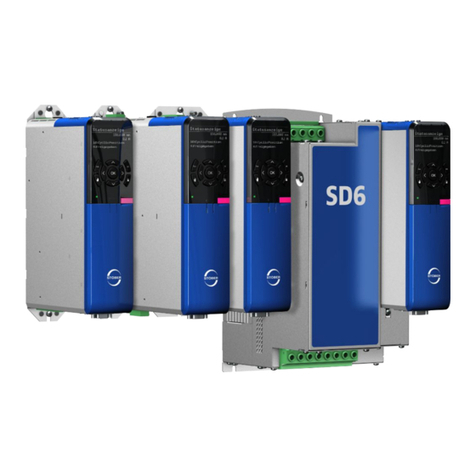
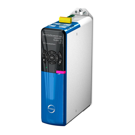
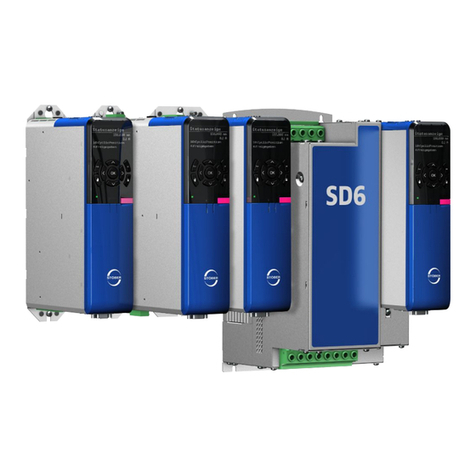
Using the CiA 402 Controller Based (CiA CB) application in the SD6 drive
controller, you can implement applications with synchronized, cyclic
assignment of reference values by a motion control unit (type MC6, for
example).
1.1 About this manual
This manual describes the control of the drive controller, operation modes and
functions of the CiA 402 Controller Based (CiA CB) application. It also
describes projecting and setup of the application and drive controller in the
DriveControlSuite commissioning software and how to place the drive and
control unit in operation.
The manufacturer-specific jog operation mode is available for commissioning,
emergency mode and for maintenance and repair work. You can also use
different operation modes as specified by CANopen device profile CiA 402.
This makes the Homing mode operation mode available for referencing. In
Production mode choose between Interpolated position mode, Cyclic
synchronous position mode, Cyclic synchronous velocity mode or Cyclic
synchronous torque mode. Associated with each operation mode is the
corresponding control mode of the drive (position, speed, or torque/force
control).
In accordance with CiA 402 you can use the Touch probe function with CiA CB
for the position measurement with a binary signal.
This documentation applies to the following devices:
• Drive controller SD6 from DriveControlSuite V 6.1-A
What is new?
Index Date Changes
00 09/2013 First edition
01 03/2014 General corrections
02 10/2015 General corrections
Supplemented:
• Object directory annex- References

ID 442454.02 5WE KEEP THINGS MOVING
General Information
1
Operation manual CiA 402 Controller Based
1.2 Further documentation
The documentation listed in the following table provides relevant information on
the SD6 drive controller. You can find the latest document versions at
www.stoeber.de (Services).
1.3 Technical support
If you have technical questions that are not answered by this document, please
contact:
• Phone: +49 7231 582-3060
• E-mail: applications@stoeber.de
Device/Software Documentation Contents ID
SD6 drive controllers Manual System
environment,
technical data,
commissioning,
communication,
diagnosis
442426
SD6 drive controllers Commissioning
instructions
Technical data,
installation,
commissioning,
function test
442537
EtherCAT EC6
communication module
Manual Technical data,
installation,
commissioning,
data transfer
442516
CANopen CA6
communication module
Manual Technical data,
installation,
commissioning,
data transfer
442637
MC6 Motion Controller Manual Technical data,
installation,
commissioning
diagnosis
442461

ID 442454.02 6WE KEEP THINGS MOVING
General Information
1
Operation manual CiA 402 Controller Based
1.4 Important information and conventions
1.4.1 Safety instructions and pictograms
The devices can represent a source of danger. Therefore observe
• the safety guidelines, technical rules and regulations given in the following
sections
• and points.
STOBER shall assume no liability for damage resulting from failure to comply
with the instruction manual or relevant regulations. We reserve the right to
make technical changes for the purpose of improving the devices.
The following conventions apply to the safety instructions used in this
documentation:
WARNING!
Warning
means that there may be a serious danger of death
if the stated precautionary measures are not taken.
1.4.2 Abbreviations, symbols, indexes
The following abbreviations, formula symbols and indices are used in this
documentation.
Information
refers to important information about the product or serves to
emphasize a section in the documentation to which the reader
should pay special attention.
Abbreviations
CAN Controller Area Network
CiA CB CiA 402 Controller Based
CiA CAN in Automation
csp Cyclic synchronous position mode
cst Cyclic synchronous torque mode
csv Cyclic synchronous velocity mode
Enc Encoder
Drive follows Drive follows the command value
IGB Integrated Bus
ip Interpolated position mode
LS Limit Switch
neg Negative
pos Positive
RS Reference Switch
ZP Zero Pulse
Formula symbol
FForce
M Torque
Indices
hex Hexadecimal

ID 442454.02 7WE KEEP THINGS MOVING
General Information
1
Operation manual CiA 402 Controller Based
1.5 Instructions for use
1.5.1 Using the software
The DriveControlSuite software package can be used to select the application
and adjust the parameters and signal monitoring of the 6th generation of
STÖBER drive controllers. The functionality is specified by selecting an
application and transmitting these data to an drive controller.
The software is the property of STÖBER ANTRIEBSTECHNIK GmbH & Co.
KG and is copyrighted. The software is licensed for the user.
The software is only provided in machine-readable form. STÖBER
ANTRIEBSTECHNIK GmbH & Co. KG gives the customer a non-exclusive
right to use the software (license) provided it has been legitimately obtained.
The customer is authorized to use the software for the above activities and
functions and to make copies of the software, including a backup copy for
support of this use, and to install same.
The conditions of this license apply to each copy. The customer promises to
affix the copyright notation to each copy of the software and all other property
notations.
The customer is not authorized to use, copy, change or pass on/transmit the
software for purposes other than those in these regulations. The customer is
also not authorized to convert the software (i. e., reverse assembly, reverse
compilation) or to compile it in any other way. The customer is also not
authorized to issue sublicenses for the software, or to rent or lease it out.
1.5.2 Product maintenance
The obligation to maintain refers to the two latest software versions created by
STÖBER ANTRIEBSTECHNIK GmbH & Co. KG and approved for use.
STÖBER ANTRIEBSTECHNIK GmbH & Co. KG will either correct software
errors or will provide the customer with a new software version. This choice will
be made by STÖBER ANTRIEBSTECHNIK GmbH & Co. KG. If, in individual
cases, the error cannot be immediately corrected, STÖBER
ANTRIEBSTECHNIK GmbH & Co. KG will provide an intermediate solution
which may require the customer to comply with special operation regulations.
A claim to error correction only exists when the reported errors are reproducible
or can be indicated with machine-generated outputs. Errors must be reported
in a reconstructable form and provide information which is useful to error
correction.
The obligation to correct errors ceases to exist for software which the customer
changes or edits in any way unless the customer can prove that such action is
not the cause of the reported error.
STÖBER ANTRIEBSTECHNIK GmbH & Co. KG will keep the respective valid
software versions in an especially safe place (fireproof data safe, bank deposit
box).

ID 442454.02 8WE KEEP THINGS MOVING
Basic information
2
Operation manual CiA 402 Controller Based
2 Basic information
Overview of sections
2.1 Controller . . . . . . . . . . . . . . . . . . . . . . . . . . . . . . . . . . . . . . . . .. . . .10
2.1.1 Device state machine according to CiA 402 . . . . . . . . . . . . . . . 10
2.2 Operating modes . . . . . . . . . . . . . . . . . . . . . . . . . . . . . . . . . .. . . .14
2.2.1 Selection of the active operation mode . . . . . . . . . . . . . . . . . . . 14
2.2.2 Jog .. . . . . . . . . . . . . . . . . . . . . . . . . . . . . . . . . . . . . . . . . . . . . . 14
2.2.2.1 Input and output signals .. . . . . . . . . . . . . . . . . . . . . . 15
2.2.2.2 Function . . . . . . . . . . . . . . . . . . . . . . . . . . . . . . . . . . . 16
2.2.2.3 Control commands and status information .. . . . . . . . 17
2.2.3 Homing mode . . . . . . . . . . . . . . . . . . . . . . . . . . . . . . . . . . . . . . 17
2.2.3.1 Input and output signals .. . . . . . . . . . . . . . . . . . . . . . 18
2.2.3.2 Reference position . . . . . . . . . . . . . . . . . . . . . . . . . . . 19
2.2.3.3 Referencing methods .. . . . . . . . . . . . . . . . . . . . . . . . 20
2.2.3.3.1 Referencing method 1 . . . . . . . . . . . . . . . 22
2.2.3.3.2 Referencing method 2 . . . . . . . . . . . . . . . 22
2.2.3.3.3 Referencing method 3 . . . . . . . . . . . . . . . 23
2.2.3.3.4 Referencing method 5 . . . . . . . . . . . . . . . 23
2.2.3.3.5 Referencing method 7 . . . . . . . . . . . . . . . 24
2.2.3.3.6 Referencing method 11 . . . . . . . . . . . . . . 25
2.2.3.3.7 Referencing method 17 . . . . . . . . . . . . . . 26
2.2.3.3.8 Referencing method 18 . . . . . . . . . . . . . . 26
2.2.3.3.9 Referencing method 19 . . . . . . . . . . . . . . 27
2.2.3.3.10 Referencing method 21 . . . . . . . . . . . . . . 27
2.2.3.3.11 Referencing method 23 . . . . . . . . . . . . . . 28
2.2.3.3.12 Referencing method 27 . . . . . . . . . . . . . . 29
2.2.3.3.13 Referencing methods 33 and 34 . . . . . . . 30
2.2.3.3.14 Referencing method 35 . . . . . . . . . . . . . . 30
2.2.3.3.15 Referencing method 37 . . . . . . . . . . . . . . 30
2.2.3.3.16 Referencing method -1 . . . . . . . . . . . . . . . 31
2.2.3.3.17 Referencing method -2 . . . . . . . . . . . . . . . 31
2.2.3.3.18 Referencing method -3 . . . . . . . . . . . . . . . 32
2.2.3.3.19 Referencing method -4 . . . . . . . . . . . . . . . 32
2.2.3.4 Control commands and status information .. . . . . . . . 33
2.2.4 Interpolated position mode . . . . . . . . . . . . . . . . . . . . . . . . . . . . 33
2.2.4.1 Input and output signals . . . . . . . . . . . . . . . . . . . . . . . 34
2.2.4.2 Control commands and status information .. . . . . . . . 35
2.2.5 Cyclic synchronous position mode . . . . . . . . . . . . . . . . . . . . . . 35
2.2.5.1 Input and output signals . . . . . . . . . . . . . . . . . . . . . . . 36
2.2.5.2 Control commands and status information .. . . . . . . . 37
2.2.6 Cyclic synchronous velocity mode .. . . . . . . . . . . . . . . . . . . . . . 37

ID 442454.02 9WE KEEP THINGS MOVING
Basic information
2
Operation manual CiA 402 Controller Based
2.2.6.1 Input and output signals .. . . . . . . . . . . . . . . . . . . . . . 38
2.2.6.2 Control commands and status information .. . . . . . . . 39
2.2.7 Cyclic synchronous torque mode . . . . . . . . . . . . . . . . . . . . . . . 39
2.2.7.1 Input and output signals .. . . . . . . . . . . . . . . . . . . . . . 40
2.2.7.2 Control commands and status information .. . . . . . . . 41
2.3 Feed forward . . . . . . . . . . . . . . . . . . . . . . . . . . . . . . . . . . . . . .. . . .42
2.3.1 Control-unit-generated external feed forward . . . . . . . . . . . . . . 42
2.3.2 Drive-generated internal feed forward .. . . . . . . . . . . . . . . . . . . 43
2.3.3 Without feed forward . . . . . . . . . . . . . . . . . . . . . . . . . . . . . . . . . 43
2.4 Interpolation .. . . . . . . . . . . . . . . . . . . . . . . . . . . . . . . . . . . . . .. . . .44
2.5 Additional functions . . . . . . . . . . . . . . . . . . . . . . . . . . . . . . . .. . . .45
2.5.1 Touch probe .. . . . . . . . . . . . . . . . . . . . . . . . . . . . . . . . . . . . . . . 45
2.5.1.1 Function . . . . . . . . . . . . . . . . . . . . . . . . . . . . . . . . . . . 45

ID 442454.02 10WE KEEP THINGS MOVING
Basic information
2
Operation manual CiA 402 Controller Based
This section contains essential information about the basic settings that must
be considered in each project for the drive controller and adjusted for your
application. The section describes control of the drive controller and the
available operating modes and also covers feed forward and interpolation. A
description of the CiA-402-compliant Touch probe function is also included.
2.1 Controller
The application is based on the internationally standardized CANopen device
profile CiA 402 for electrical drives. The SD6 drive controller is controlled
accordingly with CiA-402-compliant control and status words.
2.1.1 Device state machine according to CiA 402
The illustration below shows the device states and possible changes in state in
accordance with CiA 402.
Fig. 2-1Device state machine according to CiA 402

ID 442454.02 11WE KEEP THINGS MOVING
Basic information
2
Operation manual CiA 402 Controller Based
The table below shows the conditions for changes in the state machine.
Change of state Conditions
0 Device start-up > self test Control board power supply turned on.
1 Self test > switch on disable Self test completed without errors
AND initialization complete.
2 Switch on disable > ready to switch on Enable active
AND DC link charged
AND command Shutdown
AND safety technology deactivated
AND IGB motion bus inactive OR (IGB motion bus active AND (IGB state = 3:IGB motion bus OR IGB exception
mode active OR Local mode active)).
3 Ready to switch on > switched on Enable active
AND command Switch On
4 Switched on > operation enabled Enable active
AND command Enable operation
5 Operation enabled > switched on Enable active
AND command Disable operation
6 Switched on > ready to switch on Enable active
AND command Shutdown
7 Ready to switch on > switch on disable Enable inactive
OR DC link not charged
OR command Quick stop
OR command Disable voltage
OR safety technology active
OR (IGB motion bus active AND IGB state not equal to 3:IGB motion bus AND IGB exception mode inactive AND
local mode inactive)
8 Operation enabled > ready to switch on Shutdown command

ID 442454.02 12WE KEEP THINGS MOVING
Basic information
2
Operation manual CiA 402 Controller Based
9 Operation enabled > switch on disable Enable inactive
OR command Disable voltage
OR safety technology active
10 Switched on > switch on disable Enable inactive
OR DC link not charged
OR command Quick stop
OR command Disable voltage
OR safety technology active
OR (IGB motion bus active AND IGB state not equal to 3:IGB motion bus AND IGB exception mode inactive AND
local mode inactive)
11 Operation enabled > quick stop Command Quick stop
OR (Enable inactive AND Quick stop signal with enable off signal active)
12 Quick stop > switch on disable Quick stop complete
OR DC link below 130 V
OR safety technology active
OR command Disable voltage
13 All states > fault response active Fault detected
14 Fault response active > fault Fault response complete
15 Fault > switch on disable Command Fault reset (positive edge)
Change of state Conditions

ID 442454.02 13WE KEEP THINGS MOVING
Basic information
2
Operation manual CiA 402 Controller Based
The device state machine must receive specific commands for changes of
state. The commands are given as a bit combination in the control word in
accordance with CiA402 (parameter A515 Control word). The table below
shows the states of the bits in A515 and how they are combined for commands
(bits marked with X are irrelevant).
The standard device state machine has the same states as in the device state
machine according to CANopen device profile CiA 402.
The table below lists manufacturer-specific designations and the designations
according to CiA.
Command
Bit of the control word (A515 control word)
Bit 7 Bit 3 Bit 2 Bit 1 Bit 0
Fault
reset
Enable
operation
Quick
stop
Enable
voltage
Switch
on
Shutdown 0 X 1 1 0
Switch on 0 0 1 1 1
Disable voltage 0 X X 0 X
Quick stop 0 X 0 1 X
Disable operation 0 0 1 1 1
Enable operation 0 1 1 1 1
Fault reset Pos. of
edge X XXX
Manufacturer-specific
designation
Designation according to CiA 402
Self test Not ready to switch on
Switch on disable Switch on disabled
Ready to switch on Ready to switch on
Switched on Switched on
Operation enabled Operation enabled
Fault Fault
Fault reaction active Fault reaction active
Quick stop active Quick stop active

ID 442454.02 14WE KEEP THINGS MOVING
Basic information
2
Operation manual CiA 402 Controller Based
2.2 Operating modes
Different operation modes are available with the CiA CB application.
For commissioning, emergency mode and for maintenance and repair
work:
•Jog
Control-independent movement of the drive.
You can also use the following operation modes with CiA CB in accordance
with CANopen device profile CiA 402.
For referencing:
• Homing mode
Control-independent referencing of the drive. The drive calculates the
necessary motion profiles independently.
In production mode:
• Interpolated position mode
Cyclic position assignment by the control unit. Position-controlled drive.
• Cyclic synchronous position mode
Cyclic position assignment by the control unit. Position-controlled drive.
• Cyclic synchronous velocity mode
Cyclic velocity assignment by the control unit. Velocity-controlled drive.
• Cyclic synchronous torque mode
Cyclic torque/force assignment by the controller. Torque-/force-controlled
drive.
2.2.1 Selection of the active operation mode
You can choose the desired operation mode in parameter A541 Modes of
operation. The currently active operation mode is displayed via the parameter
A542 Modes of operation display.
2.2.2 Jog
You can use Jogging mode to move the drive independently of the control unit,
for example during commissioning, in emergency mode, or for setup and repair
work.

ID 442454.02 15WE KEEP THINGS MOVING
Basic information
2
Operation manual CiA 402 Controller Based
2.2.2.1 Input and output signals
!
!"# $%&'"
!()*'&!+
",&-!.
"
,& /
01 /
2 / !!

ID 442454.02 16WE KEEP THINGS MOVING
Basic information
2
Operation manual CiA 402 Controller Based
2.2.2.2 Function
1I13 Tip acceleration
2I45 Tip deceleration
3I18 Tip jerk
If signal TipPos is set to 1, the drive accelerates with ramp I13 and jerk limit I18
to velocity I12. If signal TipPos is set to 0, the drive brakes with ramp I45 to a
complete stop.
If signal TipNeg is active, the drive will accelerate to -I12. The same applies to
acceleration and jerk.
If signals TipPos and TipNeg are set to 1 at the same time, the drive brakes to
a complete stop:
Taste
Taste
12
3
+I12
n
-I12
0
1
0
1
+I12
n
-I12
0
1
0
1
Taste
Taste

ID 442454.02 17WE KEEP THINGS MOVING
Basic information
2
Operation manual CiA 402 Controller Based
2.2.2.3 Control commands and status information
To select the Jog operation mode, set the parameter A541 to the value -1.
The active operation mode is output in parameter A542. If Jog operation mode
is active, the display contains as information -1: Jog.
The following mode-specific bit is used in the control word A515.
No mode-specific bit is used in the status word A516.
2.2.3 Homing mode
During the referencing in Homing mode, the reference system of the machine
and controller are absolutely matched to each other. The drive is only able to
perform absolute movements in the referenced state (movements to defined
positions).
Bit Designation Comment
4 TipPos 1 = Jog in positive
direction
5 TipNeg 1 = Jog in negative
direction
Information
For all graphical displays of axes in this section, the smallest
position value is on the left, the largest on the right. Accordingly
positive motion moves to the right, negative to the left.

ID 442454.02 18WE KEEP THINGS MOVING
Basic information
2
Operation manual CiA 402 Controller Based
2.2.3.1 Input and output signals
!"#$
%&
%&#$#
%''#
()
*#+
,-.+
/+
*'+.)
()
%#
%&

ID 442454.02 19WE KEEP THINGS MOVING
Basic information
2
Operation manual CiA 402 Controller Based
2.2.3.2 Reference position
The reference position is the value that is set in the reference point. The
reference point is determined by the referencing method, which is described in
greater detail on the following pages.
Position A569 Home offset = 2.50 m is assigned to the reference point by
means referencing.
When the reference has been set, the drive comes to a complete stop just after
the reference position.

ID 442454.02 20WE KEEP THINGS MOVING
Basic information
2
Operation manual CiA 402 Controller Based
2.2.3.3 Referencing methods
You can implement the following referencing method, which are described in greater detail on the following pages.
Switch position (S) and initial direction of
travel when the switch is not activated
Referencing
method
Reference to Description
Zero pulse Limit
switch
Torque/force (M/F)
1yesyes —
Negative limit switch, encoder zero pulse,
negative initial movement.
5yes— — Negative reference switch, encoder zero
pulse, negative initial movement.
17 — yes — Negative limit switch, negative initial
movement.
21 — — — Negative reference switch, negative initial
movement.
2yesyes —
Positive limit switch, encoder zero pulse,
positive initial movement.
3yes— —
Positive reference switch, encoder zero pulse,
positive initial movement.
18 — yes — Positive limit switch, positive initial movement.
19 — — — Positive reference switch, positive initial
movement.
7yes— —
Centrally arranged reference switch,
encoder zero pulse, positive initial movement.
23 — — — Centrally arranged reference switch,
positive initial movement.
S
S
S
Table of contents
Other Stober Controllers manuals
Stober
Stober MC6 User manual
Stober
Stober SD6 Series Training manual
Stober
Stober SR6 Training manual

Stober
Stober SD6 Series User manual

Stober
Stober SC6 Series Training manual
Stober
Stober PROFINET SD6 User manual
Stober
Stober SC6 Series User manual

Stober
Stober MC6 User manual
Stober
Stober SD6 Series User manual
Stober
Stober SD6 Series User manual
