WIKA DIH10-Ex User manual

D
GB
Connection head with integrated digital display module
model DIH10-Ex
Connection head with integrated digital display
module in accordance with ATEX directive
Model DIH10-Ex
Anschlusskopf mit integriertem digitalem
Anzeigemodul nach ATEX-Richtlinie
Typ DIH10-Ex
Operating instructions
Betriebsanleitung

3330872.01 02/2014 GB/D
D
GB
WIKA operating instructions model DIH10-Ex2
© 2014 WIKA Alexander Wiegand SE & Co. KG
All rights reserved. / Alle Rechte vorbehalten.
WIKA®is a registered trademark in various countries.
WIKA®ist eine geschützte Marke in verschiedenen Ländern.
Prior to starting any work, read the operating instructions!
Keep for later use!
Vor Beginn aller Arbeiten Betriebsanleitung lesen!
Zum späteren Gebrauch aufbewahren!
Operating instructions model DIH10-Ex
Page
3 - 30
Betriebsanleitung Typ DIH10-Ex
Seite
31 - 57
Further languages can be found at www.wika.com.

GB
1. General information 4
2. Safety 6
3. Specications 12
4. Design and function 14
5. Transport, packaging and storage 17
6. Commissioning, operation 18
7. Information on mounting and operation in
hazardous areas 23
8. Maintenance and cleaning 25
9. Faults 26
10. Dismounting, return and disposal 27
Appendix: EC declaration of conformity 29
Declarations of conformity can be found online at www.wika.com.
WIKA operating instructions model DIH10-Ex 3
3330872.01 02/2014 GB/D
Contents
Contents

GB
4WIKA operating instructions model DIH10-Ex
3330872.01 02/2014 GB/D
1. General information
■
The instrument described in these operating instructions has been
designed and manufactured using state-of-the-art technology. All
components are subject to stringent quality and environmental
criteria during production. Our management systems are certied to
ISO 9001 and ISO 14001.
■
These operating instructions contain important information on
handling the instrument. Working safely requires that all safety
instructions and work instructions are observed.
■
Observe the relevant local accident prevention regulations and
general safety regulations for the instrument's range of use.
■
The operating instructions are part of the product and must be kept
in the immediate vicinity of the instrument and readily accessible to
skilled personnel at any time.
■
Skilled personnel must have carefully read and understood the
operating instructions prior to beginning any work.
■
The manufacturer's liability is void in the case of any damage
caused by using the product contrary to its intended use,
non-compliance with these operating instructions, assignment
of insuciently qualied skilled personnel or unauthorised
modications to the instrument.
■
The general terms and conditions contained in the sales
documentation shall apply.
■
Subject to technical modications.
■
Further information:
- Internet address: www.wika.de / www.wika.com
- Relevant data sheet: AC 80.11
- Application consultant: Tel.: +49 9372 132-0
Fax: +49 9372 132-406
info@wika.com
1. General information

GB
WIKA operating instructions model DIH10-Ex 5
3330872.01 02/2014 GB/D
Explanation of symbols
WARNING!
... indicates a potentially dangerous situation that can result
in serious injury or death, if not avoided.
CAUTION!
... indicates a potentially dangerous situation that can
result in light injuries or damage to equipment or the
environment, if not avoided.
Information
... points out useful tips, recommendations and information
for ecient and trouble-free operation.
DANGER!
... identies hazards caused by electrical power. Should
the safety instructions not be observed, there is a risk of
serious or fatal injury.
WARNING!
... indicates a potentially dangerous situation in the
hazardous area that can result in serious injury or death, if
not avoided.
WARNING!
... indicates a potentially dangerous situation that can result
in burns, caused by hot surfaces or liquids, if not avoided.
1. General information

GB
6WIKA operating instructions model DIH10-Ex
3330872.01 02/2014 GB/D
2. Safety
WARNING!
Before mounting, commissioning and operation, make sure
that the display is suitable for the application.
Non-observance can result in serious injury and/or damage
to the equipment.
Further important safety instructions can be found in the
individual chapters of these operating instructions.
2.1 Intended use
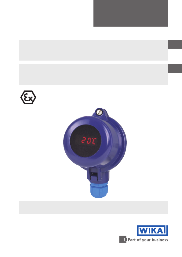
The model DIH10-Ex connection head with integrated digital display
module (digital indicator) is an all-purpose, configurable loop-powered
indicator for single resistance thermometers (RTD), thermocouples
(TC) and resistance and sensor transmitters.
It is especially applicable where a standard signal of 4 ... 20 mA is
already available.The current-loop display is built into an appropriate
connection head or wall-mounted case, and can thus be used as a
local display in all sectors of industry.The cases are not constituent
elements of the EC-type examination certificate.
The instrument has been designed and built solely for the intended
use described here, and may only be used accordingly.
The technical specications contained in these operating instructions
must be observed. Improper handling or operation of the instrument
outside of its technical specications requires the instrument to be
taken out of service immediately and inspected by an authorised
WIKA service engineer.
If the instrument is transported from a cold into a warm environment,
the formation of condensation may result in instrument malfunction.
Before putting it back into operation, wait for the instrument
temperature and the room temperature to equalise.
2. Safety

GB
WIKA operating instructions model DIH10-Ex 7
3330872.01 02/2014 GB/D
The manufacturer shall not be liable for claims of any type based on
operation contrary to the intended use.
2.2 Personnel qualication
WARNING!
Risk of injury should qualication be insucient!
Improper handling can result in considerable injury and
damage to equipment.
■
The activities described in these operating instructions
may only be carried out by skilled personnel who have
the qualications described below.
■
Keep unqualied personnel away from hazardous areas.
Skilled personnel
Skilled personnel are understood to be personnel who, based on
their technical training, knowledge of measurement and control
technology and on their experience and knowledge of country-specic
regulations, current standards and directives, are capable of carrying
out the work described and independently recognising potential
hazards.
Special operating conditions require further appropriate knowledge,
e.g. of aggressive media.
2.3 Additional safety instructions for instruments per ATEX
WARNING!
Non-observance of these instructions and their contents
may result in the loss of explosion protection.
Ex marking:
II 2G Ex ia IIC T6 (ZELM 05 ATEX 0260)
2. Safety

GB
8WIKA operating instructions model DIH10-Ex
3330872.01 02/2014 GB/D
WARNING!
The programming set for the factory programming must
only be used by the manufacturer, as it does not have
ATEX approval!
The programming of the display must only be made via the
three buttons at the rear of the display!
CAUTION!
■
The operation of these versions in Ex areas is only
permitted in intrinsically safe circuits.
■
In addition to this instruction manual, note the
accompanying EC-type examination certicate
(ZELM 05 ATEX 0260).
■
Repairs are strictly prohibited.
■
Do not use displays presenting externally visible
damage.
■
Observe the instructions for mounting and operation as
well as the requirements for the use of the devices in
hazardous areas.
WARNING!
When cases are used, they must either have their
own suitable approval or comply with the minimum
requirements. IP protection of at least IP 20 applies for all
cases.
However, light metal cases must be qualied in
accordance with EN/IEC 60079-0 section 8.1. In addition,
non-metallic cases or powder-coated cases must meet
the requirements of EN/IEC 60079-0 or have a suitable
warning note.
2. Safety

GB
WIKA operating instructions model DIH10-Ex 9
3330872.01 02/2014 GB/D
The current loop indicator can be built into either a
model BSZ-H connection head or BSS-H connection
head (with or without wall-mounting adapter). In this case,
the case requirements referred to are fullled. The cases
are not constituent elements of the EC-type examination
certicate.
2.4 Special hazards
WARNING!
Observe the information given in the applicable type
examination certicate and the relevant country-specic
regulations for installation and use in hazardous areas (e.g.
IEC 60079-14, NEC, CEC). Non-observance can result in
serious injury and/or damage to the equipment.
For additional important safety instructions for instruments
with ATEX approval see chapter 2.3 “Additional safety
instructions for instruments per ATEX”.
WARNING!
For hazardous media such as oxygen, acetylene,
ammable or toxic gases or liquids, and refrigeration
plants, compressors, etc., in addition to all standard
regulations, the appropriate existing codes or regulations
must also be followed.
WARNING!
Protection from electrostatic discharge (ESD) required!
The proper use of grounded work surfaces and personal
wrist straps is required when working with exposed circuitry
(printed circuit boards), in order to prevent static discharge
from damaging sensitive electronic components.
2. Safety

GB
10 WIKA operating instructions model DIH10-Ex
3330872.01 02/2014 GB/D
To ensure safe working on the instrument, the operating
company must ensure
■
that suitable rst-aid equipment is available and aid is
provided whenever required.
■
that the operating personnel are regularly instructed
in all topics regarding work safety, rst aid and
environmental protection and know the operating
instructions and in particular, the safety instructions
contained therein.
DANGER!
Danger of death caused by electric current
Upon contact with live parts, there is a direct danger of
death.
■
Electrical instruments may only be installed and
connected by skilled electrical personnel.
■
Operation using a defective power supply unit (e.g. short
circuit from the mains voltage to the output voltage) can
result in life-threatening voltages at the instrument!
WARNING!
Residual media in dismounted instruments can result in
a risk to persons, the environment and equipment. Take
sucient precautionary measures.
Do not use this instrument in safety or emergency stop
devices. Incorrect use of the instrument can result in injury.
Should a failure occur, aggressive media with extremely
high temperature and under high pressure or vacuum may
be present at the instrument.
2. Safety

GB
WIKA operating instructions model DIH10-Ex 11
3330872.01 02/2014 GB/D
2.5 Labelling, safety marks
Product label
■
Product labels when tted into a connection head or case
- Head/case labelling
■
Display module product label 1
3
2
4
Model
Year of manufacture
Model
Year of manufacture
- Head/case product label
2. Safety

GB
12 WIKA operating instructions model DIH10-Ex
3330872.01 02/2014 GB/D
3. Specications
Specications Model DIH10-Ex (display module)
Input
Current loop 4 ... 20 mA
Input impedance Riat 20 mA < 160 Ohm (U = < 3.2 V)
Accuracy
Resolution -999 ... 9999 digit
Measuring error ±0.2 % of measuring range, ±1 digit
Temperature drift 100 ppm/K
Display
Principle LED, rotatable in 90° steps
Measured value of display 7 segment, 8 mm high, red, 4-digit =
Display 9999
Overrange/underrange to HI / to LO
Display rate 0.1 s - 1 s - 10 s (adjustable)
Explanation of symbols
Before mounting and commissioning the instrument,
ensure you read the operating instructions!
CE, Communauté Européenne
Instruments bearing this mark comply with the relevant
European directives.
ATEX European Explosion Protection Directive
(Atmosphère = AT, explosible = EX)
Instruments bearing this mark comply with the
requirements of the European directive 94/9/EC (ATEX) on
explosion protection.
2. Safety / 3. Specications

GB
WIKA operating instructions model DIH10-Ex 13
3330872.01 02/2014 GB/D
Explosion protection, power supply
Only for connection to a certied intrinsically safe circuit with the following
maximum values:
Maximum terminal voltage U0DC 30 V
Maximum current l0100 mA
Maximum power P01 W
Maximum capacitance Cinegligibly small
Maximum inductance Linegligibly small
Ambient conditions
Operating temperature Standard version: 0 ... 80 °C
Ex version: 0 ... 60 °C
Storage temperature -20 ... +80 °C
Module housing
Dimensions Ø 43.0 / 48.5 / 62.5 mm x 37 mm
Case material Polycarbonate
Ingress protection Front: IP 67
Connection: IP 20 or IP 00
Weight approx. 55 g
Connection
Plug-in terminal strip, up to 1.5 mm²
open cable ends
Programmable features
Scale range, display time, decimal point,
unit (°C/°F), zero point stabilisation,
programming lock, reference points, TAG
number
Case designs
(see chapter 4.2)
■
Connection head (standard)
■
Wall-mount case
■
Case with pipe support
CE conformity
EMC directive
2004/108/EC, EN 61326 emission
(group 1, class A) and interference
immunity (industrial application)
ATEX directive 94/9/EC, II 2 G Ex ia IIC T6
For further specications see WIKA data sheet AC 80.11 and the order
documentation.
3. Specications

GB
14 WIKA operating instructions model DIH10-Ex
3330872.01 02/2014 GB/D
Dimensions in mm for the model DIH10-Ex display module
Connector pins for factory programming
Buttons for programming
Coupler connector
▲
▼
P
43 mm
Ø 43
Ø 48,5
Ø 62,5
40 mm
4. Design and function
4.1 Description
The model DIH10-Ex is a universal, microprocessor-controlled display,
monitoring and control instrument. It has an input, to which 4 … 20 mA
standard signals can be connected.
With its simple mounting and open programmability via the easily
accessible buttons, pressure transmitters which are already operating
can also be retrotted quickly.
The display is loop-powered, and so no additional power supply is
needed.The 8 mm high LED display ensures good readability, even in
poor lighting conditions.
Model DIH10-Ex display module, operating side
3. Specications / 4. Design and function

GB
WIKA operating instructions model DIH10-Ex 15
3330872.01 02/2014 GB/D
4.2 Case designs
4.2.1 BSZ-H connection head (standard design), DIH10-Y-*A
4.2.2 Wall-mount case, DIH10-Y-*C
Specications Standard version
Connection to thermometer d M24 x 1.5 / ½ NPT
Material Aluminium black, lacquered 1)
Cable gland 1 x M20 x 1.5 / 1 x ½ NPT
Ingress protection IP 65 (option: IP 67)
Specications Standard version
Material Aluminium black, lacquered 1)
Lower body Aluminium black, lacquered 1)
Cable gland 2 x M16 x 1.5
Ingress protection IP 65 (option: IP 67)
1) RAL 5022
14053621.0114053621.01
BSZ-H upper body special version
Weight approx. 500 g
Weight approx. 350 g
4. Design and function

GB
16 WIKA operating instructions model DIH10-Ex
3330872.01 02/2014 GB/D
4.2.3 Case with pipe support, DIH10-Y-*D
4.3 Scope of delivery
Cross-check scope of delivery with delivery note.
Weight approx. 950 g
BSZ-H upper body special version
14078928.01
Specications Standard version
Material Aluminium black, lacquered 1)
Lower body Aluminium black, lacquered 1)
Pipe support Stainless steel
Pipe diameter R 1" ... 2"
Cable gland 2 x M16 x 1.5
Ingress protection IP 65 (option: IP 67)
1) RAL 5022
2x M16x1,5
95
20
25
136
91
2x M16x1,5
95
20
25
136
91
2x M16x1,5
95
20
25
136
91
4. Design and function

GB
WIKA operating instructions model DIH10-Ex 17
3330872.01 02/2014 GB/D
5. Transport, packaging and storage
5.1 Transport
Check the instrument for any damage that may have been caused by
transport. Obvious damage must be reported immediately.
5.2 Packaging
Do not remove packaging until just before mounting.
Keep the packaging as it will provide optimum protection during
transport (e.g. change in installation site, sending for repair).
5.3 Storage
Permissible conditions at the place of storage:
■
Storage temperature: -20 ... +80 °C
■
Humidity: 35 ... 85 % relative humidity (no condensation)
Avoid exposure to the following factors:
■
Direct sunlight or proximity to hot objects
■
Mechanical vibration, mechanical shock (putting it down hard)
■
Soot, vapour, dust and corrosive gases
Store the instrument in its original packaging in a location that fulls
the conditions listed above. If the original packaging is not available,
pack and store the instrument as described below:
1. Wrap the instrument in an antistatic plastic lm.
2. Place the instrument along with shock-absorbent material in the
packaging.
3. If stored for a prolonged period of time (more than 30 days), place a
bag containing a desiccant inside the packaging.
WARNING!
Before storing the instrument (following operation), remove
any residual media.This is of particular importance if
the medium is hazardous to health, e.g. caustic, toxic,
carcinogenic, radioactive, etc.
5. Transport, packaging and storage

GB
18 WIKA operating instructions model DIH10-Ex
3330872.01 02/2014 GB/D
6. Commissioning, operation
WARNING!
■
Never connect directly to a voltage supply (e.g. 24 V) as
this will damage the display.
■
Only use a transmitter that will not exceed the
permissible electrical limit values.
6.1 Operating a current loop
Power
supply
unit
DC 24 V
internal
bridge
DIH10-Ex
display
Case
WARNING!
The display is only ever operated in a 4 ... 20 mA current
loop. A direct connection to a voltage supply (e.g. DC 24 V)
will lead to the display being damaged and will invalidate
the warranty.
For a functional check, the display must be powered from a
mA source (e.g. mA transmitter or calibrator).
In normal operation, the display is connected in series with
a 4 ... 20 mA transmitter or connected to the 4 ... 20 mA
analogue output of an instrument.
6. Commissioning, operation

GB
12
+-
4 ... 20 mA
21
4 ... 20 mA
+-
+
-
2341
+-
+
-
+
-
=
=
 ̄
+ (1)
- (2)
+
-
4 ... 20 mA
+
-
+
4 ... 20 mA
+ +- - -
L1 N
DIH10-Ex
Trans-
mitter
Trans-
mitter
WIKA operating instructions model DIH10-Ex 19
3330872.01 02/2014 GB/D
6.2 Model DIH10-Ex connection
The 4-pin terminal block for the connection of the current-loop display
is located on the rear of the display and is accessible once the case is
open.
Terminal 1: Positive terminal of the current loop
Terminal 2: Negative terminal of the current loop
Terminals 3 and 4 are connected together on the PCB and enable the
convenient connection of a transmitter built into the connection head.
Con-
trollers
Ex area
Transmitter
supply isolator
Maximum terminal voltage: DC 30 V
Maximum current: 100 mA
Voltage drop: 3.2 V
Maximum power: 1 W
Data
logger
Display
instrument
Connection examples
12
+-
4 ... 20 mA
21
4 ... 20 mA
+-
+
-
2341
+-
+
-
+
-
+ (1)
- (2)
4 ... 20 mA
+
4 ... 20 mA
+ +- - -
DIH10
Trans-
mitter
Trans-
mitter
Internal bridge
Power
supply
unit
Plug-in terminal strip
6. Commissioning, operation

GB
20 WIKA operating instructions model DIH10-Ex
3330872.01 02/2014 GB/D
■
Model DIH10-Ex (Ex version)
+
-
-
+
-
+
-
-
-
-
2
1
3
4
-
+
4 ... 20 mA
current loop
Power supply
Transmitter supply isolator
Ex ia IIC
Trans-
mitter
internal
bridge
Case *)
DIH10-Ex
display
Interconnection in
accordance with
EN 60079-14
Non-hazardous area Ex area
4 ... 20 mA
current loop
*) The cases are not constituent elements of the EC-type examination certicate.
6. Commissioning, operation
Other manuals for DIH10-Ex
1
Table of contents
Languages: