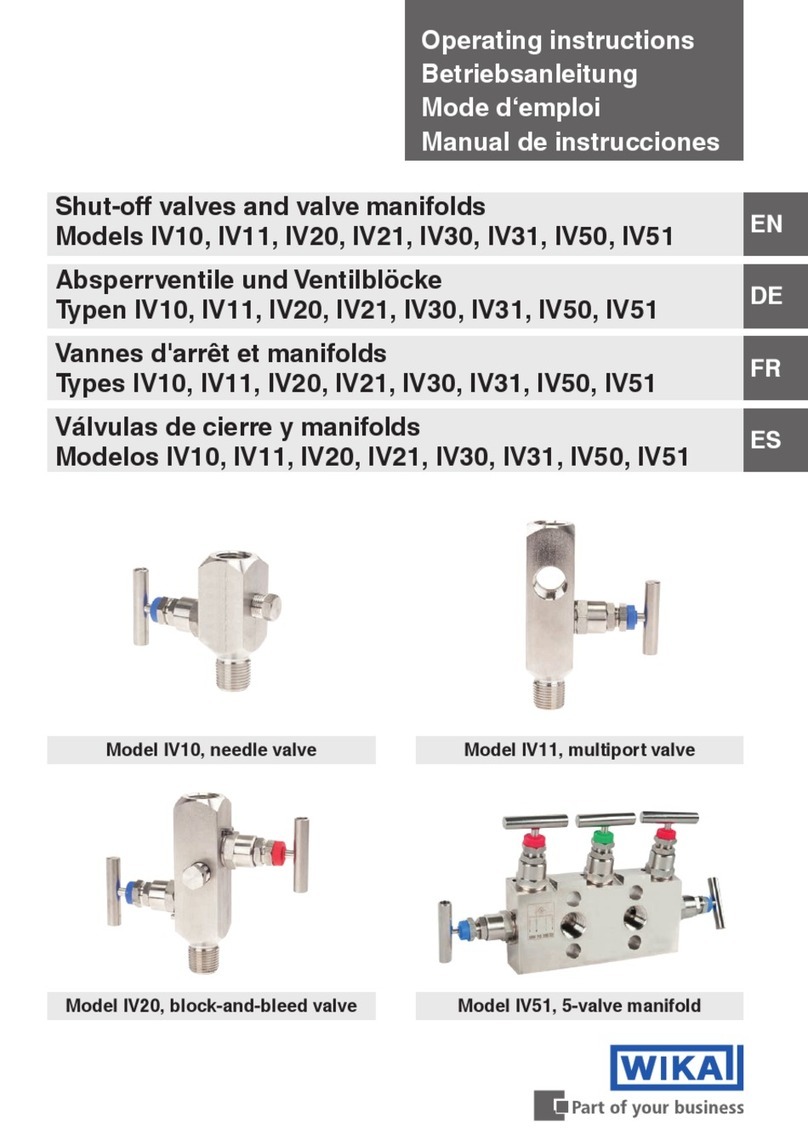
WIKA IBF1 User manual

MTUT001VPEN
Floating Monoblock Installation
Operating Manual
REV. A
PAG. 1/9
MONOBLOCK
INSTRUMENTATION VALVES
Models IBF1, IBF2, IBF3, IBM, IBS, IBJ
INSTALLATION, OPERATING & MAINTENANCE
MANUAL
A 25/10/21 Prima emissione – Sostituisce MTUT001VPEN Santimaria A. Rigo F. Chiarin N.
Rev. Date Description Prepared by Verified by Approved by

MTUT001VPEN
Floating Monoblock Installation
Operating Manual
REV. A
PAG. 0/9
Summary
1. INTRODUCTION ................................................ 1
2. WARRANTY CONDITIONS ............................... 1
3. VALVES IDENTIFICATIONS ............................. 2
4. HANDLING AND STORAGE ............................. 2
5. OPERATING INSTRUCTIONS .......................... 2
6. INSTALLATION ................................................. 2
7. COMMISSIONING.............................................. 3
7.1. PRESSURIZATION .......................................3
7.2. CHECK OF EXTERNAL TIGHTNESS ................3
7.3. CONTROL OF INTERNAL TIGHTNESS (ONLY
DBB SERIES).....................................................3
8. MAINTENANCE ................................................. 4
8.1. MAINTENANCE WITHOUT DISASSEMBLY;.......4
8.2. MAINTENANCE WITH DISASSEMBLY;.............4
9. DISASSEMBLY.................................................. 4
9.1. REPLACEMENT OF CLOSURES RINGS AND
SEATS (FIG.1) ....................................................4
9.2. REPLACEMENT OF STEM SEALS (FIG.2) .......4
9.3. REPLACEMENT OF BONNET SEALS (FIG.3) ...4
10. ASSEMBLY OF THE VALVE............................. 5
11. LUBRICANT....................................................... 6
12. TIGHTENING TORQUES................................... 6
12.1.FLANGES BOLTS TIGHTENING TORQUE
6
12.2.STEM TIGHTENING TORQUE
6
13. SUGGESTED SPARE PARTS........................... 6

www.wika.com 1
1. INTRODUCTION
This manual is intended as a guide to assist customers
in the installation, and maintenance of WIKA instruments
Monoblock Instrumentation Valves series (ball/needle).
Before using any of these series valves, read the entire
Installation and Operation Manual (IOM) carefully and
make sure you understand everything.
If in doubt, please consult with WIKA Instruments Italia’s
technical dept.
WARNINGS & SAFETY
INSTRUCTIONS
WIKA instruments Monoblock Ball Valves must only
be used, installed, and repaired in accordance with
these instructions.
In the event of leakage or other malfunction, please
contact a qualified service person, as a continued
operation may cause system failure or a general
hazard.
Keep hands and objects away from the valve ports at
all times.
Before removing a valve from the line, always make
sure the line has been depressurized and drained.
Cycle the valve a few times to relieve any pressure
that could be trapped in the body cavity.
Always wear Personal Protective Devices when
handling a valve especially with toxic, flammable or
corrosive fluids.
Do not operate valves with visible leaks: valves have
to be isolated and repaired.
Valve surface temperature may become extremely
hot or cold due to operating conditions. Avoid any type
of direct contact with the valve that may cause harm
or injury.
The valves should be used in a well-designed,
adequately supported piping system in order not to be
subjected to undue forces, stresses or shock loads
during service.
The system should be adequately protected to ensure
that external and internal pressure and temperature
limits do not exceed the valve limits.
Never look into the valve bore while the valve is in a
flow line. Pressure and fluids could escape from the
valve causing harm or injury.
The Monoblock ball valves are fit to be used
completely open or completely closed: therefore they
shall not be used for flow lamination.
Monoblock ball valves are not designed to undergo
full ∆P. Monoblock ball valves shall be operated with
maximum 4bar (60psi) ∆P.
Always use WIKA original spare parts.
2. WARRANTY CONDITIONS
It is suggested to always check the contract for
clarification about warranty terms and conditions.
Warranty will ever falls in case of:
-Dismantling under warranty period on
customer own initiative;
-Product is used in an improper way;
-Careless handling;
-Damage from external causes;
-Alteration/modification from original design;
-Excessive wear;
-Use out of design parameters;
If a malfunction occurs during the warranty period,
please contact the nearest WIKA dealer for the best
solution.
Sizes included:
½” – ¾” – 1” – 1” ½ – 2”
DN 15 – 25 – 40 – 50
Series:
Single block (IBF1)
Single Block and bleed or SBB
(IBF2, IBM2)
Double block and bleed or DBB
(IBF3, IBM3, IBS3, IBJ4)

www.wika.com 2
3. VALVES IDENTIFICATIONS
We recommend checking, before commissioning, that
the conditions of use are in compliance with the design
specification of the valve.
Valves features can be read on the tag plate attached to
the valve body.
Valves identifications included:
-Part number
-Inlet & outlet dimensions and class
-Tag number
-Heat codes
-Drain size
-Specification applied
-Lot number
4. HANDLING AND STORAGE
Valves shall be stored in a dry and clean place.
Condensation shall be avoided through suitable warming
and ventilation system.
Prior to storage, inspect the valve for shipping damage.
Keep all protective packaging, flange covers and end
caps attached to the valves during storage.
During storage valves shall be kept in close position to
avoid introduction of foreign bodies.
Carbon steel valves have an oil finish to retard rusting
during storage: it is not a substitute for paint or other
means of protective coating to be applied to the valve
once installed.
Stainless steel valves have their natural finish and do not
require additional protection once installed.
Valves shall be handled by use of lifting lugs or other
suitable lifting devices.
It is suggested not to lift the valves by means of valve
handles.
5. OPERATING INSTRUCTIONS
On manual operated valves, the valve operation is done
by turning the valve handle 90° clockwise to open
(handle is parallel to flow line), and 90° counter clockwise
to close (handle is perpendicular to flow line).
The bleed line should be in closed position while flow line
is in open position, and open when flow line is in closed
position. To open the bleed valve, turn counter clockwise
the T bar up to the limit. To close turn clockwise the T
bar.
Before starting to open the bleed valve is suggested to
remove the plug on the bleed line if any.
6. INSTALLATION
Monoblock instrumentation valves are potentially
bidirectional so they do not have preferential flow
direction.
Just before installation unpack the valve and remove the
flange and closure fitting protection: ensure that no
packing material are in the flow passages or attached to
the body.
Check for damage and internal and external corrosion if
any.
Inspect the functionality of the valve opening and close
few times both flow line and bleed line.
Balls shall be in open position during the installation to
avoid their damage.
Make sure that flange faces and threads ends are free
from damage, rust, dust or foreign bodies.
It is suggest to clean flanged pipeline connection before
the installation of the valve (flush with nitrogen or other
inert gas) and to remove foreign bodies or dirt from the
internal of the pipes.
If welding operations are required ensure that
temperature do not exceed 150°C. We recommend to
keep the ball in open position.
Gaskets, flange bolts, bolts torque value, sealants,
adapters and tube fittings are responsibility of the
customer.
VALVE OPEN VALVE CLOSED

www.wika.com 3
7. COMMISSIONING
7.1. Flow diagram
Single block
Single block & bleed
Double block
Double block & bleed
Handle Colors:
-Red =drain/vent
-Blue = isolate
7.2. Pressurization
After installation check that installation of the lines,
included bleeding line, is correctly executed and that
bleed valve is closed.
Check that balls are open.
Before pressurizing with process gas, the entire line shall
be purged by means of inert gas (nitrogen). During the
line purging the valve shall be cycled a few times to
ensure the purging of the body cavity.
Purging of the lines shall be done according to a detailed
procedure from the customer or the contractor in charge
for the plant installation.
After purging, slowly pressurize the plant or plant section
with process fluid by means of upstream process valve
or other system.
During the pressurization with process fluid, cycle the
valve few times to ensure the pressurization of the body
cavity.
After the pressurization, set the valve in the required
position.
7.3. Check of external tightness
Valves have been already pneumatically and
hydrostatically factory tested so the valves do not need
to be retested at site.
Tightness test on flange between valves and line is
required.
The tightness test of the flange connections to the plant
shall be carried out in accordance to the customer
procedures.
Flange tightness test can be performed with foaming
solution applied to the joints: if no bubble appears than
test is acceptable.
In case of liquids, tightness is ensured if no visible leaks
appear.
It is suggested to pressurize the plant step-by-step and
to perform the flange leak test each step.
7.4. Control of internal tightness (only DBB
models)
After line pressurization close both the ball valves.
To check the internal tightness remove the plug on bleed
line, if any, and open the bleed valve.
Check that there is no constant fluid leak from the bleed
line.

www.wika.com 4
8. MAINTENANCE
To prevent leakage (internal and external) or malfunction
due to the wear and seals degradation, the final user
must establish a preventive maintenance and inspection
program.
The program shall consider two type of operations:
-Maintenance without disassembly;
-Maintenance with disassembly;
Frequency of maintenance depends on fluid quality,
environment conditions and system working conditions.
8.1. Maintenance without disassembly
This type of maintenance does not require the
disassembly of the valve from the line and can be done
as routine maintenance. This shall include at least:
-Walk around: visually check that everything
goes right, valve is in their normal position, no
vibrations occur, place is clean and nothing
hinders the valve operation;
-External leak check: inspect the equipment to
locate possible leaks
-External coating check: inspect the coating to
prevent rust formation, peeling and any type of
damage on coating;
-Complete stroke: open and close the valve’s
handles (balls and needles) to make sure they
are not stuck;
-Loose check: check tightening of levers and all
the threaded connections to avoid loosening of
equipment;
If a leak is detected on the stem during the check, tighten
the gland nut about a 1⁄6 -turn as a routine maintenance
procedure. This will compensate for any wear or settling
of the gland packing. Excessing tightening of stem nut
can result in high valve operating torque.
8.2. Maintenance with disassembly
WARNING
Disassembly of the valve during the warranty
period determines the end of the warranty
This type of maintenance require the disassembly of the
valve from the process line.
-Internal check: Inspection of parts to detect loss
of wall thickness which may result in decreased
pressure capacity. Check for internal wear of
the valve bore, flange connection, threaded
connections, ball, stem etc.;
-Seals replacement: replace seals and seats of
the complete valve for proper operation;
We suggest the use of WIKA Instruments original spare
parts kit. The kit is composed of: valve seats, soft rings
seals, graphite rings, metal seal rings
In addition to repair kits, other spare parts are available
from WIKA, such as: valve balls, stems, glands, bolts,
screws and nuts. Should additional parts be required, it
is recommended that the complete valve is replaced.
9. DISASSEMBLY
During the operation of disassembly it is important to
avoid any damage of the seals surfaces.
Before disassembling the valve from the line it is
suggested to purge the line using inert gas (Nitrogen).
During the purging of the line and then during
depressurization, open the valve at 45° to purge and
depressurize the body cavity.
Prior to servicing the valve, bring it to the open position
making sure to release line pressure and drain all
trapped media in the valve cavity.
It is suggested to place the valve on a work bench and
not on the ground. During the operation be careful not to
introduce foreign bodies or dirt like sand, dust or others.
9.1. Replacement of ball valve flow seals (Fig.1)
1. Unscrew inlet closure fitting (1) or/and unscrew
terminal closure fitting (7);
2. Remove closure gasket ring (2);
3. Remove spacer (3) if any;
4. Remove first seat (4);
5. Set ball in closed position;
6. Remove ball (5);
7. Remove second seat (6)
9.2. Replacement of stem seals (Fig.2)
1. Unscrew stem nut (1);
2. Remove lever (2);
3. Unscrew adjustment stem nut (3)
4. Remove metal gland ring (4)
5. Remove packing ring (5)
6. Remove stem from opened side of the valve, be
careful not to damage the seal surfaces of stem and
closures (7);
7. Remove seal ring (6)
9.3. Replacement of bonnet (Fig.3)
1. Unscrew T-bar internal screw (1);
2. Remove T-bar (2);
3. Remove cap (3);
4. Remove complete bonnet;
WARNING
It is highly recommended to change all the
graphite and metals seals once they have been
dismantled from body.

www.wika.com 5
Fig.1
Fig.2
Fig.3
10. ASSEMBLY OF THE VALVE
For the assembly it is suggested to place the valve in
vertical position clamped on the work bench.
1. Insert the first seat (fig.1 - 6)
2. Lubricate stem thread and place internal packing
ring
(even spring and ball if antistatic design required);
3. Insert the stem through the side of the valve, be
careful not to damage the sealing surface; guide it
up to the stem bore;
4. Holding up the stem, insert external packing rings,
the gland ring
5. Place locking clip if any;
6. Thread the stem nut onto the stem. Tighten the stem
nut;
7. Place the lever and the stem nut; tight the nut;
8. Place levers in closed position;
9. Place the ball and maintaining the lever in close
position to prevent the ball from falling;
10. Place second seat (fig.1 – 4) and then the spacer (if
any);
11. Place closure gasket ring on closure fitting and put
a small quantity of lubricant on thread to help its
insertion on body;
12. Place closure on its body housing and tight;
13. Leave the valve in open position for line flushing.
14. Repeat from p.1 for the other ball
For bonnet:
1. Prepare the new bonnet with needle in open
position;
2. Screw the bonnet on its body housing and tight;
3. Place the red cap pushing it on the packing gland;
4. Place T bar on stem and the screw from the side of
T bar;
5. Place new seal ring on body and then screw the
body bonnet into the valve body.

www.wika.com 6
11. LUBRICANT
The valves are already lubricated during the
assembly phase for the following reasons:
-ease the components assembly
-improve maneuverability
-ease the preservation in case of warehouse
storage;
The type of lubricant depends on the type of fluid and
pressure/temperature conditions. We suggest the using
of the following:
-Natural gas, oil, hydrocarbon fluids: Molycote
Longterm W2 for seals and Molycote HSC plus
for threaded connections;
-Oxygen: Solvay Fomblin oil or Dupont Krytox;
-Food products: Vaseline or similar nontoxic
materials;
For special applications we suggest to require
information specifying in detail the type of fluid and the
operating conditions.
12. TIGHTENING TORQUES
12.1. Flanges bolts Tightening Torque
12.2. Stem tightening torque
There is not a value for stem tightening torque.
Nuts have to be screwed up to the end, then the plate
springs (Belleville washers) have to be released
unscrewing the nut ½ turn.
13. SUGGESTED SPARE PARTS
The suggested spare parts are usually:
-Soft Rings seals (statics and dynamics);
-Fire safe rings (Graphite rings);
-Metal seal rings;
-Ball seats
When ordering the spare parts, list:
-Type of valve;
-Serial no;
-Year of manufacture;
-Type of fluid used;
-Part no. (position);
-Quantity
Other parts such as plugs, bleeders, stems, bonnets etc.
are available upon request.
Thread
in
Torque N/m
A193 B8 -
B8M CL.1
A193 B8M
CL.2
A193 B7
A320 L7
1/4 9 13 14
5/16 18 26 29
3/8 31 46 52
7/16 50 74 83
1/2 76 112 127
9/16 109 162 183
5/8 151 223 252
3/4 268 395 447
7/8 431 636 720
1 /0 646 954 1079

www.wika.com 7
WIKA INSTRUMENTS ITALIA Srl
Via Bernarde 11/1
36047 Montegaldella (VI)
Italy
Tel.
+39 0444 635801
Other manuals for IBF1
1
This manual suits for next models
5
Table of contents
Other WIKA Control Unit manuals
Popular Control Unit manuals by other brands

IFM Electronic
IFM Electronic Ecomat 300 AC2618 operating instructions

TUMAC
TUMAC EL7 Series maintenance

Cailabs
Cailabs CANUNDA-PULSE installation manual

Afag
Afag LE-50 Series Translation of the Original Montage Instructions

Hirschmann
Hirschmann GREYHOUND GRM20 user manual

ES-System
ES-System ES-AW-8 user manual

National Instruments
National Instruments cRIO-9068 Getting started guide

Siemens
Siemens 3KC ATC6300 operating instructions

Firmtech
Firmtech FB153BC user guide

Moxa Technologies
Moxa Technologies WAPN001 user manual

Huawei
Huawei MU509 Series Acceptance Inspection Guide

Isenberg
Isenberg TVH.4801 installation manual