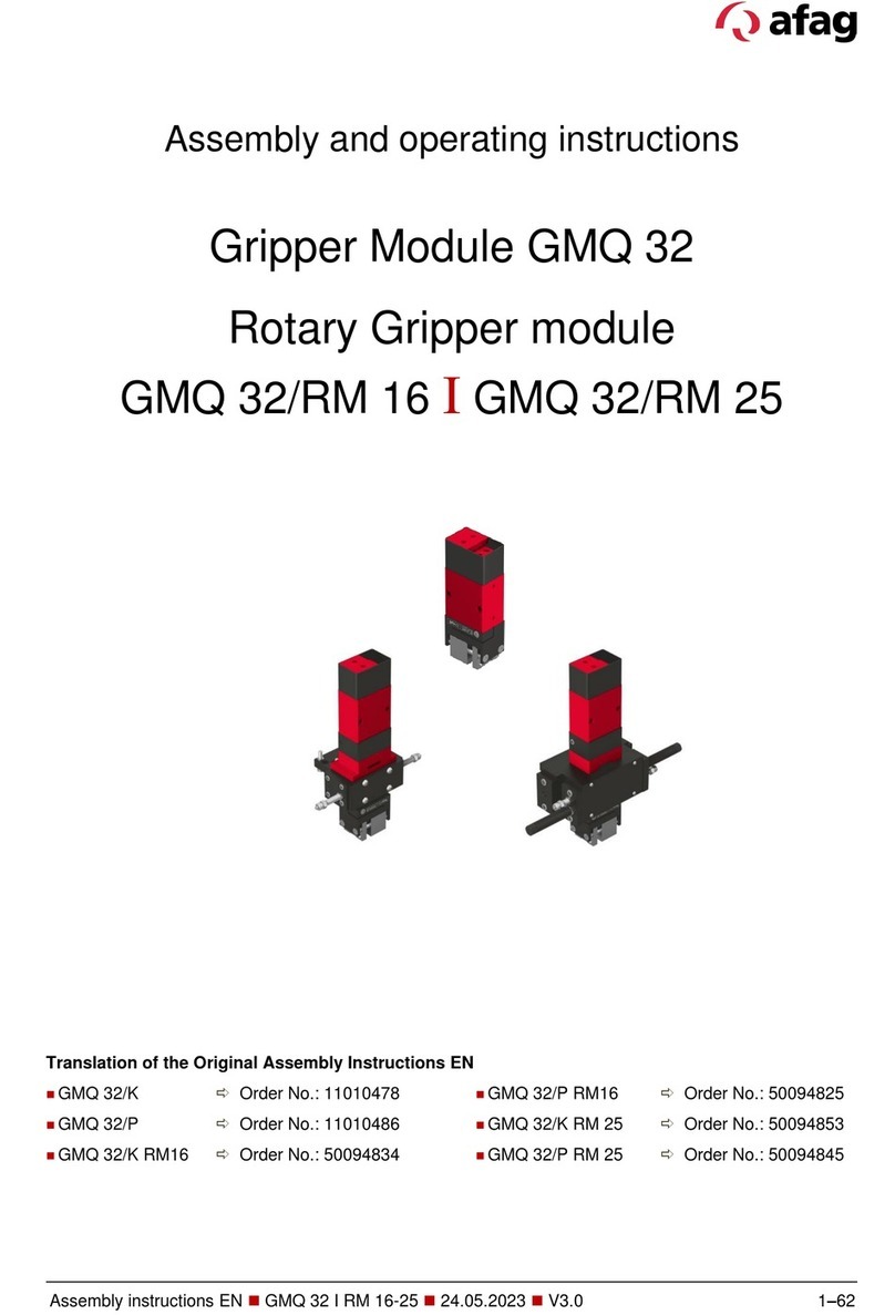
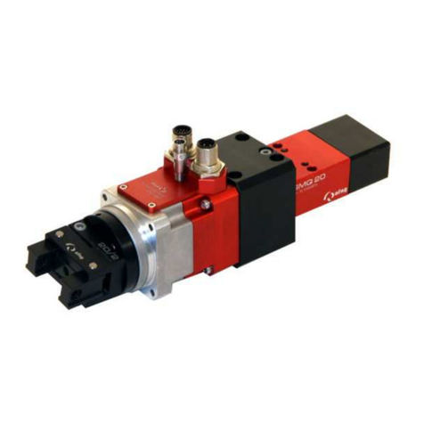
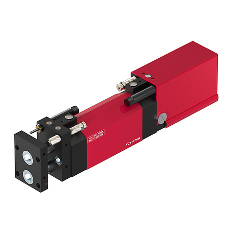
Afag LE-50 Series User manual

Linear modules electrical
LE-50 I LE-60 I LE-70
Declaration of Incorporation
Module Information
Montage Instructions
Maintenance Instructions
“Translation” of the Original Montage Instructions
© Copyright by Afag Automation AG

12 LE-50-LE-60-LE-70-OI-vers. 2.1 gb. 28.07.14
These Montage Instructions apply to:
Type Order No.
Type Order No.
LE-50-XXX 50407225
LE-50-D-XXX 50407228
LE-60-XXX 50407226
LE-60-D-XXX 50407229
LE-70-XXX 50407227
LE-70-D-XXX 50407230
Assembly and initial start-up must be carried out by qualified personnel only and ac-
cording to these Montage Instructions.
Version of this docu-
mentation:
LE-50-LE-60-LE-70-OI-vers. 2.1 gb. 28.07.14
Symbols:
DANGER
Indicates an immediate threatening danger.
Non-compliance with this information can result in death or se-
rious personal injuries (invalidity).
WARNING
Indicates a possible dangerous situation.
Non-compliance with this information can result in death or se-
rious personal injuries (invalidity).
CAUTION
Indicates a possibly dangerous situation.
Non-compliance with this information can result in damage to
property or light to medium personal injuries.
NOTE
Indicates general notes, useful operator tips and operating recom-
mendations which don't affect safety and health of the personnel.

LE-50-LE-60-LE-70-OI-vers. 2.1 gb. 28.07.14 3
Contents
1.0.0 EC Declaration for Incorporation..........................................................5
2.0.0 Module Information.................................................................................7
2.1.0 Safety.............................................................................................................7
2.1.1 Transport, Handling, Storage .........................................................................7
2.1.2 Module Description.........................................................................................8
Description of the module types ...................................................................10
2.1.3 Installation, Connection................................................................................11
2.1.4 Installation and mounting options.................................................................12
Tightening moments for bolts .......................................................................13
2.1.5 Installation into a system..............................................................................14
2.1.6 Preferred combinations to LE-50..................................................................16
2.1.7 Preferred combinations to LE-60..................................................................17
2.1.8 Preferred combinations to LE-70..................................................................18
2.1.9 Electrical interfaces (pin assignment)...........................................................19
2.2.0 LE linear programming modules...................................................................20
3.0.0 Montage Instructions............................................................................21
3.1.1 The delivery..................................................................................................22
3.1.2 Intended use.................................................................................................22
3.1.3 Warranty.......................................................................................................23
3.1.4 Safety...........................................................................................................23
3.1.5 Dimensional drawing LE-50..........................................................................24
3.1.6 Technical data LE-50....................................................................................25
3.1.7 Dimensional drawing LE-60..........................................................................26
3.1.8 Technical data LE-60....................................................................................27
3.1.9 Dimensional drawing LE-70..........................................................................28
3.2.0 Technical data LE-70....................................................................................29
3.2.1 Slide unit load factors LE-50.........................................................................30
3.1.2 Slide unit load factors LE-60.........................................................................31
3.1.3 Slide unit load factors LE-70.........................................................................32
3.1.4 Noise emissions ...........................................................................................33
12 LE-50-LE-60-LE-70-OI-vers. 2.1 gb. 28.07.14
3.1.5 Commissioning, Operation, Training................................................................33
3.1.6 Preparation for commissioning.........................................................................34
3.1.7 Commissioning.................................................................................................35
3.1.8 Set conversion .................................................................................................36
3.1.9 Normal operation..............................................................................................37
4.0.0 Maintenance Instructions......................................................................38
4.1.0 Maintenance....................................................................................................38
4.1.1 Regular maintenance....................................................................................... 39
4.1.2 Lubrication of the linear module slide ............................................................. 40
Additional maintenance .................................................................................. 40
4.1.3 Troubleshooting and repair...............................................................................45
4.1.4 Trouble when carrying out the reference run....................................................46
4.1.5 Accessories.....................................................................................................48
4.1.6 Exchange and repair.......................................................................................48
5.0 Disposal .........................................................................................................49
6.0 Annex..............................................................................................................49
6.1 List of figures...................................................................................................49
6.2 List of tables....................................................................................................49

LE-50-LE-60-LE-70-OI-vers. 2.1 gb. 28.07.14 5
-Machinery Directive 2006/42/EC
-Low voltage Directive 2006/42/EC
-EMV-Guideline 2004/108
-EC Production Safety Directive 2001/95
-EC RoHS 2002/95/EG
-The relevant technical documentation is compiled in accordance with part B of
Annex VI
-The relevant technical documentation in accordance with part B of Annex VI
will be transmitted in response to a reasonable request by the national authori-
ties in printed from or in electronic from (pdf).
Notes to the declaration of Incorporation according to the Machinery directive
2006/42/EC, Annex IIB, section 4
(Checklist on accurate and basic health and safety requirements).
-1.1; 1.1.1; 1.1.2; 1.2; 1.2.1; 1.2.3; 1.2.4.4; 1.2.5; 1.3; 1.3.2; 1.3.5; 1.3.6; 1.3.7; 1.3.8.1;
1.3.8.2; 1.3.9; 1.4; 1.4.1; 1.5; 1.5.1; 1.6; 1.6.1; 1.6.3; 1.6.4; 1.7; 1.7.1; 1.7.4.; 1.7.4.1;
1.7.4.2; 1.7.4.3; 3.3.5; 3.4.
-Increase of the harmonized standards applied:
-EN 349; EN ISO 12100-1; EN 12100-2; EN ISO 14121-1; EN 60204-1:2006 partly
fulfilled
This partly completed machinery must not be put into service until the final machinery
into which it is to be incorporated has been declared in conformity with the provisions
of this Directive 2006/42/EC, where appropriate.
The actual serial number will be sticked in
here upon delivery of the device.
1.0.0 EC Declaration for Incorporation
1.1.0 According to 2006/42/EC dated 09. June 2006, Appendix II B VI for
Incorporation of partly completed machinery.
The manufacturer: Afag Automation AG, Fiechtenstrasse 32, CH-4950 Huttwil
Tel. 0041 (0)62 959 87 02, www.afag.com
As manufacturer of the partly completed machine we declare that:
-The specified machine corresponds to the listed essential requirements of the
directive 2006/42/EG, wehere applicable the other directives and standards
listed below.
Producte name: LE Linear Modules (electric)
Types: LE-50-XXX LE-50-D-XXX
LE-60-XXX LE-60-D-XXX
LE-70-XXX LE-70-D-XXX
Aktuelle Serien No.
einkleben.

12 LE-50-LE-60-LE-70-OI-vers. 2.1 gb. 28.07.14
Name and address of the person authorised to compile the relevant technical documentation:
Lanz Beat, PM & Marketing-Services, Afag Automation AG
Place/Date: Huttwil, 28.07.2014
Markus Werro
Managing Director
Afag Automation AG
Siegfried Egli
Head of HT
Afag Automation AG

LE-50-LE-60-LE-70-OI-vers. 2.1 gb. 28.07.14 7
2.0.0 Module Information
2.1.0 Safety
DANGER
The strong magnetic fields of the LME may interfere with and
impair the function of electronic devices, such as pacemakers,
even when the module is switched off.
Persons with a pacemaker must keep a safety distance of at
least 50 cm.
Modifications to the linear modules LE that are not described in this Montage Instruc-
tion or have not been approved in writing by the company Afag Automation AG are
not permitted. In case of improper changes or assembly, installation, operation,
maintenance or repairs, Afag Automation AG rejects all liability.
2.1.1 Transport, Handling, Storage
For transport and storage, the following must be met:
Temperature storage: 0-50°C
Air humidity: <90%, non condensing
CAUTION
The LE linear modules are packed. In case of improper handling
the module may drop out when it is unpacked and cause inju-
ries to limbs.
The LE linear modules have a weight from 5 to 40 kg (depending on the stroke
length).
NOTE
Please note:
A technical safety information sheet is enclosed with each module.
This information sheet must be read by every person who operates
the module.

12 LE-50-LE-60-LE-70-OI-vers. 2.1 gb. 28.07.14
CAUTION
Be careful when packing and unpacking the LE linear module.
Remove the foam rubber covers on the permanent magnets
carefully.
Caution: The upper side of the cantilever arm is strongly mag-
netic. Avoid contact with metal objects and watches.
If not handled carefully the LME linear module may cause inju-
ries to fingers as the module can be moved back and forth
when it is not securely fixed.
2.1.2 Module Description
The LE linear modules are electrical modules with a non-contact and wear-free direct
drive (linear motor). They are exclusively suitable for the horizontal movement of
module superstructures and loads.
The LE linear modules are designed for being operated with the Afag SE-Power con-
trol system. They can also be operated with other controller types.
Further technical details are to be found in Chapter 3.5 of these Montage Instruc-
tions.
CAUTION
Within view of the LE-axis using only magnetic field resistant sensors with
shielded cable. If this is ignored, the sensors can provide unforeseen signals to
the controller, which can lead to dangerous situations!
.
Danger of bruises
The profile is strongly magnetic!
Covers

LE-50-LE-60-LE-70-OI-vers. 2.1 gb. 28.07.14 9
1. Basic unit
2. Cantilever arm
3. Primary part
4. Secondary part
5. Aluminium profile
6. Linear guide
7. Measuring head
8. Measuring tape
9. End plate
10.Lubrication nipple
11.Limit stop
12.Motor/encoder con-
nector
1
2
5
8
7
6
4
9
11
10
12

12 LE-50-LE-60-LE-70-OI-vers. 2.1 gb. 28.07.14
The LE linear module consists of the basic unit (1) and the cantilever arm (2). The
primary part (7) of the linear motor, the measuring head (5) and the motor or encoder
connector (11) are integrated in the slide. The cantilever arm (2) consists of an alu-
minium profile (2) with the mounted-on linear guide (6), secondary parts (8) and
measuring tape (4).
Due to the electromagnetic field around the motor coils which develops after power
was supplied to the primary part force is applied on the secondary part (permanent
magnets) resulting in a linear movement.
The measuring system operates without contact according to the magnetic principle
and transmits an incremental, digital signal to the control system.
The direct drive offers the following benefits:
1. no elasticity as no transmission elements installed (belts, gears etc.)
2. no play, no hysteresis
3. no friction and thus wear-free (except for the linear guide
4. direct position measurement enables high dynamics and precision
Description of the module types
The LE-linear module is available in the following models:
Type
Stroke length
LE-50-XXX
100 bis 600 mm (Gradation 20 mm)
LE-60-XXX
100 bis 800 mm (Gradation 20 mm)
LE-70-XXX
100 bis 1000 mm (Gradation 20 mm)

LE-50-LE-60-LE-70-OI-vers. 2.1 gb. 28.07.14 11
2.1.3 Installation, Connection
WARNING
The LE linear modules are moved by the electric control. If the
linear modules cannot move freely there is danger of injuries
and bruises near the add-ons.
If add-ons at the LE linear modules could cause danger in con-
nection with the moving slide or superstructures a safe opera-
tion must be ensured.
WARNING
Due to the decentral controller the operator of the LE linear
module needs not to be near the product so that third persons
might be endangered by the module operation.
Always switch off the controller and protect it from being
switched on again unintentionally when you work on the LE lin-
ear module. The signals of the control system may cause unin-
tentional movements of the module which may lead to personal
injuries.
CAUTION
Within view of the LE-axis using only magnetic field resistant sensors with
shielded cable. If this is ignored, the sensors can provide unforeseen signals to
the controller, which can lead to dangerous situations!
.

12 LE-50-LE-60-LE-70-OI-vers. 2.1 gb. 28.07.14
2.1.4 Installation and mounting options
The LE linear modules are designed for cantilever operation. They can however also
be used as gantry version.
Cantilever operation Gantry application
Movable cantilever
Firmly mounted cantilever
Firmly mounted slide
Movable slide
Useful load on the cantilever arm
Useful load on the slide
NOTE
Please note:
The LE linear modules are approved for horizontal applications.
Vertical operation is not permitted as lowering of the axis cannot be
prevented when power is not applied because braking function is
interrupted.

LE-50-LE-60-LE-70-OI-vers. 2.1 gb. 28.07.14 13
WARNING
Due to the decentral controller the operator of the LE linear
module needs not to be near the product so that third persons
might be endangered by the module operation.
Always switch off the controller and protect it from being
switched on again unintentionally when you work on the LE lin-
ear module. The signals of the control system may cause unin-
tentional movements of the module which may lead to personal
injuries.
The mounting grids and the mounting threads are shown on the dimensional draw-
ings in chapter 3.5, page 19 of these Montage Instructions. (Further accessories can
be found in the technical catalogue or on the website www.afag.com
Use the centering bushings included in the scope of supply to determine the position
and insert these bushings in the opposite borings of the mounting grid.
Tightening moments for bolts
The screws to be used for assembly must at least satisfy the following conditions:
Standard: VDI 2230
Strength: class 8.8
Surface: galvanized blue, oiled or greased
Thread
Tightening moments
M2
M2,5
M3
0,3 … 0,35 Nm
0,5 … 0,73 Nm
1,1 … 1,4 Nm
M4
2,6 … 3,3 Nm
M5
5,2 … 6,5 Nm
M6
9,0 ... 11,3 Nm
M8
21,6 … 27,3 Nm
Table 1: Tightening moments for bolts

12 LE-50-LE-60-LE-70-OI-vers. 2.1 gb. 28.07.14
2.1.5 Installation into a system
The series of the LE linear modules is used for the linear, smooth movement of rigid-
ly mounted loads under the ambient and Installation conditions defined for this mod-
ule, see Technical data in chapter 3.5 of these Installation Instructions.
DANGER
The LE linear modules must not be used in an explosion-
hazardous environment.
WARNING
The LE linear modules are moved by the electric control. If the
LE linear modules cannot move freely there is danger of injuries
and bruises near the add-ons. If add-ons at the LE linear mod-
ules could cause danger in connection with the moving slide a
safe operation must be ensured.
Ensure that the operator cannot reach into the operating range
of the LE linear modules during normal operation.
Ensure that there is no danger to the operator of the system in
special operating modes. The concept depends on the safety
concept of the system and the integrated modules.
WARNING
Due to the decentral controller the operator of the LE linear
module needs not to be near the product so that third persons
might be endangered by the module operation.
Deactivate release of the controller while you are working on
the LE linear module and activate the controller again only after
work is finished.

LE-50-LE-60-LE-70-OI-vers. 2.1 gb. 28.07.14 15
CAUTION
The LE linear module is a partly complete machine.
The LE linear modules must be integrated in the safety concept
of the system so that a safe operation can be ensured.
Ensure that the operating personnel cannot reach into the op-
erating range of the LE linear modules during operation.
Depending on the module version and the installation there is
an additional safety risk by e.g. squeezing a finger.
The LE linear module may only be used in accordance with the
intended purpose.
Ensure that the operator cannot reach into the operating range
of the LE linear module during normal operation. This can be
achieved by taking appropriate safety measures such as cas-
ings, a light grid or by disconnecting the drive from the power
supply.
NOTE
This Montage Instructions should be read carefully before carrying
out any activity on or with the LE linear module.

12 LE-50-LE-60-LE-70-OI-vers. 2.1 gb. 28.07.14
2.1.6 Preferred combinations to LE-50

LE-50-LE-60-LE-70-OI-vers. 2.1 gb. 28.07.14 17
2.1.7 Preferred combinations to LE-60

12 LE-50-LE-60-LE-70-OI-vers. 2.1 gb. 28.07.14
2.1.8 Preferred combinations to LE-70

LE-50-LE-60-LE-70-OI-vers. 2.1 gb. 28.07.14 19
2.1.9 Electrical interfaces (pin assignment)
Motor connector pinout:
Pin
Signal
1
Motor winding 1 (U)
5
Motor winding 2 (V)
2
Motor winding 3 (W)
PE
GND Motor (PE)
6
Temperature sensor PTC
4
Temperature sensor PTC
Encoder connector pinout
Pin
Signal
1
+ 5V DC, Encoder
2
GND Encoder
3
Canal A
4
Canal A/
5
Canal B
6
Canal B/
7
Canal Z
8
Canal Z/
9
Temperature sensor + (KTY84-130)
10
11
12
Temperature sensor - (KTY84-130)
Not used
Not used
Figure 1: Pin Assignment
2
1
PE
5
4
Motor
Encoder
Encoder
Motor
6
1
2
3
4
5
6
7
8
9
10
12
11

12 LE-50-LE-60-LE-70-OI-vers. 2.1 gb. 28.07.14
2.2.0LE linear programming modules
CAUTION
The LE linear modules should be started up in set-up or jog
mode. A wrong programming may trigger uncontrolled move-
ments of the LE linear modules. Fast or unintentional move-
ments of the module can result in personal injury and damage
to property.
The programming depends on the control system used. Observe the respective
manuals of the control system supplier.
If the Afag SE-Power control system is used, please observe the Montage Instruc-
tions which are supplied together with the control system.
You can also download this Montage Instructions from the Afag website:
www.afag.com
WARNING
If wrong basic data is input at the PLC the LE linear module may
move unhindered against the stopper leading to injury to per-
sons by parts flying around.
In case of a failure of the displacement encoder or a defective
limit switch cable the LE linear module may execute unexpected
movements. Persons working on the system may be injured.
WARNING
It is the responsibility of the system manufacturer to ensure
that the system is protected with a safety fence so that persons
are not injured during operation.
HINWEIS
The referencing of the axis is
always retracted on the male
side, (0 position). Should this be
possible when mounting the axis
is not in a system, the axis must
be installed rotated through 180 °.
This manual suits for next models
5
Table of contents
Other Afag Control Unit manuals

Afag
Afag GMQ 32/RM 16 User manual

Afag
Afag GMQ 32 Series User manual

Afag
Afag RM 25 User manual

Afag
Afag CR 12 User manual

Afag
Afag LM 12/30 User manual

Afag
Afag GMQ 12 RE-50 User manual

Afag
Afag Compact Slide CS 8 User manual

Afag
Afag LM 32 User manual

Afag
Afag RM 12 Technical specifications

Afag
Afag RE-50 User manual
Popular Control Unit manuals by other brands

BVA Hydraulics
BVA Hydraulics PR33 instruction manual

Allen-Bradley
Allen-Bradley 1771-OG installation instructions

Aaeon
Aaeon PER-C10L Quick installation guide

Flight Systems
Flight Systems SCU 9iS Installation & operation manual

Parker
Parker D1FH series installation manual

Plum
Plum ecoLAMBDA installation manual