ES-System ES-AW-8 User manual
WARUNKI OGÓLNE
Moduł awaryjny należy instalować zgodnie z niniejszą instrukcją, z zachowaniem norm dotyczących bezpieczeństwa użytkowania. Wszelkie czynności instalacyjne i konserwacyjne należy wykonywać
po odłączeniu napięcia zasilającego oraz baterii. Montażu i konserwacji mogą dokonywać wyłącznie osoby mające odpowiednie uprawnienia.
Dokonywanie zmian w konstrukcji urządzenia, a także stosowanie go w warunkach innych niż opisane w niniejszej instrukcji jest niedozwolone.
CHARAKTERYSTYKA
Moduł awaryjny do współpracy ze źródłami światła typu LED.
Układ elektroniczny modułu awaryjnego zapewnia
automatyczne ładowanie baterii akumulatorów
• zabezpieczenie przed głębokim rozładowaniem baterii akumulatorów
• sygnalizację poprawne działanie oraz uszkodzenie modułu
W zestawie znajdują się:
• układ elektroniczny w obudowie
• bateria bezobsługowych akumulatorów Ni-MH
• uchwyty montażowe lub obudowę do baterii w zależności od zastosowania
• instrukcja obsługi
SYGNALIZACJA STANÓW PRACY
Dioda LED Stan pracy
Świeci Poprawne działanie, ładowarka sprawna
Nieświeci Praca w trybie awaryjnym, brak ładowania
GWARANCJE
Firma ES-SYSTEM gwarantuje (zgodnie z OWU) poprawne i niezawodne działanie swoich urządzeń pod warunkiem użytkowania zgodnie z przeznaczeniem oraz zasadami określonymi w instrukcji.
Wyroby są produkowane w oparciu o najnowsze technologie i spełniają Polskie Normy i zharmonizowane normy Unii Europejskiej.
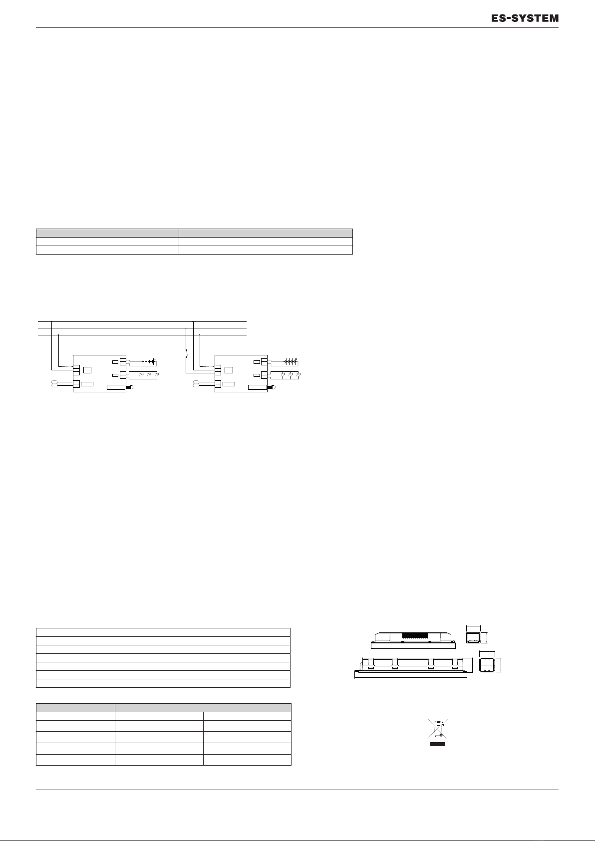
SCHEMATY POŁĄCZEŃ
SPOSÓB DZIAŁANIA
Pierwsze uruchomienie
Z uwagi na konstrukcję akumulatora Ni-MH, w celu zapewnienia prawidłowego uformowania akumulatora zaleca się, aby pierwsze ładowanie trwało nieprzerwanie przez 48 godzin. W tym czasie niedopusz-
czalne jest wyzwalanie jakichkolwiek testów oraz praca modułu w trybie awaryjnym. Po upływie tego czasu należy doprowadzić do przejścia modułu w tryb pracy awaryjnej (poprzez odłączenie zasilania
w linii L*). Moduł powinien pracować w tym trybie, aż do całkowitego wyczerpania akumulatorów. Przywrócenie napięcia zasilającego i ładowanie akumulatorów przez min. 36 godzin kończy cykl formowania.
EKSPLOATACJA
Testowanie STI:
Należy regularnie (zgodnie z normą PN-EN 50172) testować funkcjonalność modułu awaryjnego poprzez odłączanie napięcia na linii kontrolnej L* lub za pomocą opcjonalnego przycisku P2 podłączonego
do zacisków T1, T2.
Funkcje pomocnicze:
Blokada trybu awaryjnego za pomocą sygnału sterującego z jednostki RM. Po uaktywnieniu blokady moduł podczas zaniku napięcia sieciowego w linii L* nie przejdzie w tryb awaryjny. Ponowne włączenie
napięcia sieciowego w linii L* przywraca normalny sposób pracy. Blokada trybu awaryjnego z jednostki sterującej RM z łącznikiem bi-stabilnym utrzymuje blokadę trybu awaryjnego do momentu odbloko-
wania. Szczegółowe informacje techniczne oraz schematy połączeń zawarte są w instrukcji jednostki sterującej RM.
SPOSÓB INSTALACJI
Elementy modułu awaryjnego są przeznaczone do zamontowania w oprawie oświetleniowej. Dioda sygnalizacyjna powinna być widoczna w czasie eksploatacji oprawy oświetleniowej. Dopuszcza się insta-
lowanie modułu w innych warunkach, na przykład w przestrzeni międzystropowej, pod rygorem zachowania wymogów bezpieczeństwa użytkowania urządzeń i instalacji elektrycznych. Długość przewodu
pomiędzy modułem awaryjnym a diodą LED 1W nie może przekroczyć 1 m. Moduł awaryjny i bateria powinny być odsunięte od źródeł ciepła. Temperatura obudowy elektroniki zmierzona w punkcie Tc nie
może przekraczać wartości maksymalnej. Linia kontroli napięcia L* nie może zawierać wyłączników lub innych urządzeń, które mogą spowodować rozłączenie linii. Układ połączeń oprawy należy wykonać
zgodnie z jednym ze schematów zawartych w niniejszej instrukcji. Przed załączeniem napięcia należy upewnić się, że wszystkie połączenia są wykonane poprawnie.
Nie dopuszcza się możliwości ładowania baterii za pomocą innych urządzeń niż układ elektroniczny modułu awaryjnego.
Dane techniczne ES-AW-8 STI
Napięcie zasilania 230 VAC +-10% 50-60Hz
Maksymalny pobór mocy 6W
Stopień ochrony IP20
Klasa ochronności II
Zakres temperatur pracy Ta = 0..+50*C
Masa elektroniki 0,36 kg
Przekrój przewodów 0,2 – 1,5 mm^2
Kody zamówieniowe
Czas podtrzymania
ES-AW-8 1h 3h
260mA 9346110 ES-AW-8-SKTA/TC1 9346130 ES-AW-8-SKTA/TC3
450mA 9346210 ES-AW-8-SLTA/TC1 9346230 ES-AW-8-SLTA/ TC3
700mA 9346310 ES-AW-8-SMTA/TC1 9346330 ES-AW-8-SMTA/TC3
1200mA 9346410 ES-AW-8-SNTA/ TC1 9346430 ES-AW-8-SNTA/TC3
Instrukcja obsługi modułów ES-AW-8
Niesprawne moduły awaryjne oraz akumulatory
należy zwracać do dostawcy w celu dokonania
recyclingu.
Wymiary modułu awaryjnego i akumulatora
RM
RM
RM
RM
L*
L
N
N
L*
L
RM
RM
-
+
-
+
BLOKADA
230 V
50 Hz
LED
BAT
MODUŁ ES-AW-8
DIODA
SYGNALIZACYJNA
N
L*
L
RM
RM
-
+
-
+
BLOKADA
230 V
50 Hz
LED
BAT
MODUŁ ES-AW-8
DIODA
SYGNALIZACYJNA
L*
L
N
N
L*
L
DA
DA
-
+
-
+
DALI / CTI
230 V
50 Hz
LED
BAT
MODUŁ ES-AW-8
DIODA
SYGNALIZACYJNA
DA
DA
N
L*
L
DA
DA
-
+
-
+
DALI / CTI
230 V
50 Hz
LED
BAT
MODUŁ ES-AW-8
DIODA
SYGNALIZACYJNA
DA
DA
STI
CTI/ATI
/CTI-DALI
190
23
232
30
31
30
32
02.2016

User manual – ES-AW-8
GENERAL CONDITIONS
Moduł awaryjny należy instalować zgodnie z niniejszą instrukcją, z zachowaniem norm dotyczących bezpieczeństwa użytkowania. Wszelkie czynności instalacyjne i konserwacyjne należy wykonywać
The emergency module must be installed in accordance with these instructions, while maintaining safety standards. All installation and maintenance activities must be carried out after disconnecting the
supply voltage and the battery. Installation and maintenance may only be performed by authorized persons.
Making changes in the device’s design and using it under conditions other than those described in these instructions is prohibited.
FEATURES
Emergency module for use with LED light sources.
• The emergency module’s electronic system features the following functions:
• - automatic battery charging
• - battery protection against deep discharge
• - indicating correct functioning or damage to the module
The set includes:
• - the electronics encased in housing
• - maintenance-free Ni-MH batteries
• - mounting brackets or battery housing depending on the application
• - instruction manual
OPERATION MODE INDICATION
LED Operation mode
On Correct operation, charger working
O Emergency operation, not charging
GUARANTEE
ES-SYSTEM guarantees the correct and reliable operation of its devices (according to the general terms and conditions), provided they are used as intended and in accordance with the principles in the
instructions. The products are manufactured using the latest technologies and compliant with Polish standards and harmonized European Union standards.
WIRING DIAGRAMS
FUNCTIONING PRINCIPLES
First-time operation
Due to the construction of the Ni-MH battery and in order to ensure its proper formation, it is recommended that its rst charging lasts 48 hours. During this time, emergency operation is not allowed and no
testing can be performed. After this time, the module must be switched to emergency operation (by disconnecting the voltage in the L* line). The module should operate in this mode until the batteries are
completely depleted. The power supply voltage must then be switched back on, and the batteries must be charged for at least 36 hours in order to complete the formation cycle.
USE
Testing:
The emergency module functionality must be tested regularly (in accordance with the PN-EN 50172 standard) by disconnecting the voltage in the L* control line or by using the optional P2 button connec-
ted to the T1, T2 terminals.
Supporting functions:
Emergency mode blocking is possible using the control signal from the RM unit. Once the block is activated, the module will not switch to the emergency mode during a power failure in the L* line. Once mains
power is restored to the L*line, normal operation will resume. Blocking the emergency mode from the RM control unit with a bi-stable connector maintains the emergency mode block until it is removed.
Detailed technical information and wiring diagrams can be found in the instruction manual of the RM control unit.
INSTALLATION
The components of the emergency module are intended for installation in a luminaire. The LED indicator must be visible during use and in dierent conditions, for example in the ceiling void – this is mandatory
due to safety requirements applicable during the use of electrical devices and installations. The cable length between the emergency module and the 1W LED may not be longer than 1 m. The emergency
module and the battery must not be placed near heat sources. The temperature of the electronics housing measured at the Tc point must not exceed the maximum value. The voltage control line L* must not
include switches or other devices which could disconnect the line. The luminaire connection system should be carried out according to one of the wiring diagrams included in this instruction manual. Before
switching on the voltage, it is necessary to make sure that all the connections have been performed correctly.
Charging the battery with any device other than the electronics system of the emergency module is not allowed.
ES-AW-8 STI technical data
Power supply voltage 230 VAC +-10% 50-60Hz
Maximum power consumption 6W
Ingress protection rating IP20
Safety class II
Operating temperaturę range Ta = 0..+50*C
Weight of the electronics 0,36 kg
Wire cross-section 0,2 – 1,5 mm^2
Ordering codes
Autonomy time
ES-AW-8 1h 3h
260mA 9346110 ES-AW-8-SKTA/TC1 9346130 ES-AW-8-SKTA/TC3
450mA 9346210 ES-AW-8-SLTA/TC1 9346230 ES-AW-8-SLTA/ TC3
700mA 9346310 ES-AW-8-SMTA/TC1 9346330 ES-AW-8-SMTA/TC3
1200mA 9346410 ES-AW-8-SNTA/ TC1 9346430 ES-AW-8-SNTA/TC3
Faulty emergency modules and batteries must
be returned to the supplier for recycling.
The dimensions of the emergency module and the battery
RM
RM
RM
RM
L*
L
N
N
L*
L
RM
RM
-
+
-
+
INHIBIT MODE
230 V
50 Hz
INHIBIT MODE
LED
BAT
ES-AW-8 MODULE
N
L*
L
RM
RM
-
+
-
+
230 V
50 Hz
LED
BAT
ES-AW-8 MODULE
L*
L
N
N
L*
L
DA
DA
-
+
-
+
DALI / CTI
230 V
50 Hz
LED
BAT
ES-AW-8 MODULE
DA
DA
N
L*
L
DA
DA
-
+
-
+
DALI / CTI
230 V
50 Hz
LED
BAT
ES-AW-8 MODULE
DA
DA
STI
CTI/ATI
/CTI-DALI
LED INDICATOR LED INDICATOR
LED INDICATOR LED INDICATOR
190
23
232
30
31
30
32
02.2016
Table of contents
Languages:


