Dantel 44098 User manual

CAUTION
•Install or remove modules from the shelf only when the power is off.
If you install a module in the shelf with the power on, the internal
circuitry may suffer damage and the product warranty will be void.
•Remove and install circuit boards only in a static-safe environment
(use antistatic wrist straps, smocks, footwear, etc.).
•Keep circuit boards in their antistatic bags when they are not in use.
•Do not ship or store circuit boards near strong electrostatic, electromag-
netic, magnetic, or radioactive fields.
•For more complete information on electrostatic discharge safety
precautions, refer to BellcoreTM Technical Reference # TR-NWT-000870.
Copyright 1999 by Dantel, Inc. • Dantel is a registered trademark of Dantel, Inc. • ISO 9001 Registered
Printed in the U.S.A.
INSTALLATION & OPERATION MANUAL
44098-0199 <90-00131>
44098
DIODE MODULE
About this Practice:
This practice has been reissued to:
• Meet ISO 9001 requirements.
Issue date: January 1999
Reissued Practices: Updated and
new content can be identified by a
banner in the outside margin.
UPDATED
Table of Contents
Ordering Information ........................................................................... 2
General Description.............................................................................. 2
Circuit Description ............................................................................... 2
Application Information ....................................................................... 4
Installation............................................................................................ 4
Technical Specifications ....................................................................... 5
Warranty ............................................................................................... 6
A11-44098-00 REV__
44098-00
Diode Module

PAGE 2 44098-0199 <90-00131>
ORDERING INFORMATION
NOTE: This section lists the different options available for this product. To order any of the avail-
able options, contact Dantel Inside Sales through our toll-free number, 1-800-432-6835.
OPTION NUMBER FEATURES
A11-44098-00 Diode Module
GENERAL DESCRIPTION
The 44098 Diode Module provides 28 one-ampere diodes for
general purpose low-power isolation applications between
circuits, circuit components, and peripheral devices.
The 44098 is a plug-in printed circuit module that fits into any
Dantel 400-type or similar equipment housing.
The 44098 comes as a basic unit only with no options, accepts no
subassemblies, and requires no external power.
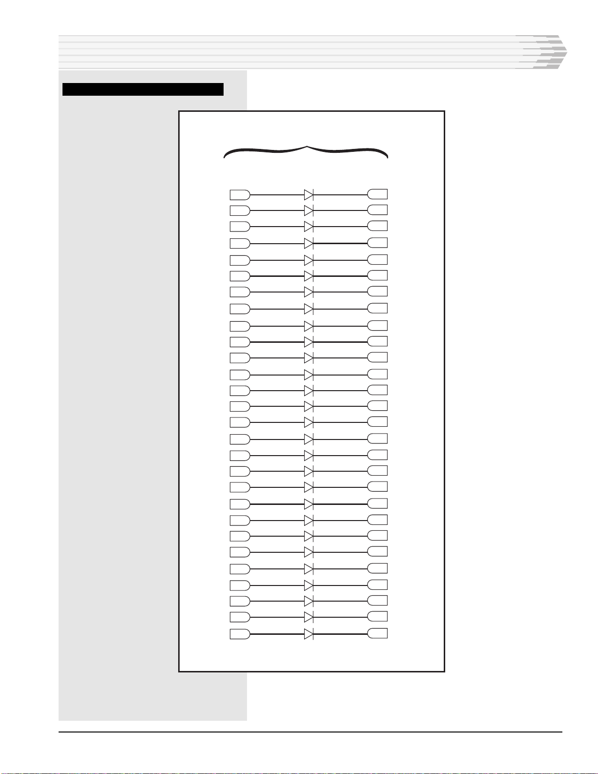
CIRCUIT DESCRIPTION
The 44098 Diode Module functional schematic is shown in
Fig. 1.
The circuit board consists of 28 1N4005 one-ampere diodes, each
connected individually to edge connector pins on the module.
Pin designations for the diodes are arranged so that all cathodes
are connected to even numbered pins, and all anodes to odd
numbered pins. Refer to Fig.1.
44098-0199 <90-00131> PAGE 3
FIG. 1 - FUNCTIONAL SCHEMATIC
CIRCUIT DESCRIPTION
1D1 2
3D2 4
5D11 6
7D20 8
9D3 10
11 D12 12
13 D21 14
15 D4 16
17 D13 18
19 D22 20
21 D5 20
23 D14 24
25 D23 26
27 D6 28
29 D15 30
31 D24 32
33 D7 34
35 D16 36
37 D25 38
39 D17 40
41 D26 42
43 D18 44
45 D27 46
47 D8 48
49 D28 50
51 D19 52
53 D9 54
55 D10 56
Anodes Cathodes
Pin Numbers

PAGE 4 44098-0199 <90-00131>
1
3
5
7
9
11
13
27
15
17
19
21
23
25
2
4
6
8
10
12
14
28
16
18
20
22
24
26
29 30
31 32
33 34
35 36
37 38
39 40
41 42
44
46
48
50
52
54
56
43
45
47
49
51
53
55
Output A Output C
Output B Output D
Inputs
1-6
Inputs
7-12
Inputs
13-18
Inputs
19-24
APPLICATION INFORMATION
The primary application of the 44098 Diode Module is to
provide general purpose low-power isolation applications
between circuits, circuit components, and peripheral devides.
Refer to Fig. 2 for an example application.
FIG. 2 - EXAMPLE APPLICATION. SUMMING CIRCUITS (NEGATIVE LOGIC), 44098
INSTALLATION
Install the module in the proper slot in the shelf. Normally the
56-pin edge connector for the slot is prewired at the factory. If
you are going to wire the connector, refer to Fig. 1 for connector
pin wiring assignments. Wire the connector in the shelf or
housing as required.

44098-0199 <90-00131> PAGE 5
TECHNICAL SPECIFICATIONS
DESCRIPTION
Maximum Diode Rating
Peak Repetitive Reverse Voltage (FROM)
Working Peak Reverse Voltage (VRWM)
DC Blocking Voltage (VR)
Non-Repetitive Peak Reverse Voltage (halfwave, single phase, 60HZ)
RMS Reverse Voltage (VR(RMS))
Average Rectified Forward Current (IO)
Non-Repetitive Peak Surge Current (IFSN)
Diode Electrical Characteristics
Maximum Instantaneous Forward Voltage Drop (vF)
Typical
Maximum
Maximum Full-Cycle Average Forward Voltage Drop (VF(AV))
Maximum Reverse Current (IR)
@ 25° C Junction Temperature (typical)
@ 25° C Junction Temperature (maximum)
@ 100° C Junction Temperature (typical)
@ 100° C Junction Temperature (maximum)
Maximum Full-Cycle Average Reverse Current (IR(AV))
Operating Temperature Range
Physical Dimensions
Weight
VALUE
600 Volts
600 Volts
600 Volts
720 Volts
420 Volts
1.0 Amp
30 Amps
0.93 Volts
1.1 Volts
0.8 Volts
0.05 uA
10 uA
1.0 uA
50 uA
30 uA
0° to 60° C.
1.4" x 6" x 5.6"
3.9 ounces

PAGE 6
6 PAGES 44098-0199 <90-00131>
LIMITED WARRANTY
The Seller warrants that the standard hardware products sold will be free from defects in material and work-
manship and perform to the Seller’s applicable published specifications for a period of 18 months for hardware,
and 3 months for software, from the date of the original invoice. The liability of the Seller hereunder shall be
limited to replacing or repairing, at its option, any defective products which are returned F.O.B. to the Seller’s
plant, (or, at the Seller’s option, refunding the purchase price of such products). In no case are products to be
returned without first obtaining permission and a customer return authorization number from the Seller. In
no event shall the Seller be liable for any consequential or incidental damages.
Equipment or parts which have been subject to abuse, misuse, accident, alteration, neglect, unauthorized
repair or installation are not covered by warranty. The Seller shall make the final determination as to the
existence and cause of any alleged defect. No warranty is made with respect to custom equipment or products
produced to the Buyer’s specifications except as specifically stated in writing by the Seller in the contract for
such custom equipment.
This warranty is the only warranty made by the Seller with respect to the goods delivered hereunder, and may
be modified or amended only by a written instrument signed by a duly authorized officer of the Seller and
accepted by the Buyer.
Warranty and remedies on products not manufactured by the Seller are in accordance with warranty of the
respective manufacturer. THE SELLER MAKES NO OTHER WARRANTY OF ANY KIND WHATSOEVER,
EXPRESSED OR IMPLIED; AND ALL IMPLIED WARRANTY OF FITNESS FOR A PARTICULAR PUR-
POSE WHICH EXCEEDS THE AFORESAID OBLIGATIONS IS HEREBY DISCLAIMED BY THE SELLER.
INCASE OF DIFFICULTY
If you experience difficulty with this equipment, check the following, as appropriate:
1. Switch settings
2. Signal levels
3. Software configuration
4. Connections between Dantel’s equipment and your equipment.
If there is still a problem, substitute equipment that is known to be good. For additional assistance, call
Dantel’s Technical Field Service Department weekdays, 6 A.M. to 5 P.M. pacific time:
1-800-4DANTEL(1-800-432-6835).
If a thorough checkout shows a piece of equipment has malfunctioned, you may return it to the factory. For
repairs and emergency replacements, obtain a Return Material Authorization (RMA) number from the Cus-
tomer Service Representative at 1-800-4DANTEL (1-800-432-6835).
To ensure expedient processing of your order, provide a purchase order number and shipping and billing
information when requesting an RMA number. Also, when the units are returned to Dantel, include a descrip-
tion of the failure symptoms for each unit returned. Send defective equipment to:
Dantel, Inc. • 2991 North Argyle Avenue • Fresno, California 93727-1388
P.O. Box 55013 • Fresno, CA 93747-5013 Phone (559) 292-1111 Fax (559) 292-9355 http://www.dantel.com
WARRANTY
This manual suits for next models
1
Table of contents
Other Dantel Control Unit manuals


Popular Control Unit manuals by other brands

Festo
Festo Compact Performance CP-FB6-E Brief description

Elo TouchSystems
Elo TouchSystems DMS-SA19P-EXTME Quick installation guide

JS Automation
JS Automation MPC3034A user manual

JAUDT
JAUDT SW GII 6406 Series Translation of the original operating instructions

Spektrum
Spektrum Air Module System manual

BOC Edwards
BOC Edwards Q Series instruction manual

KHADAS
KHADAS BT Magic quick start

Etherma
Etherma eNEXHO-IL Assembly and operating instructions

PMFoundations
PMFoundations Attenuverter Assembly guide

GEA
GEA VARIVENT Operating instruction

Walther Systemtechnik
Walther Systemtechnik VMS-05 Assembly instructions

Altronix
Altronix LINQ8PD Installation and programming manual


