10
WILDEN PUMP & ENGINEERING CO.
SECTION 7A
INSTALLATION – T4 PLASTIC
AIR-OPERATED PUMPS
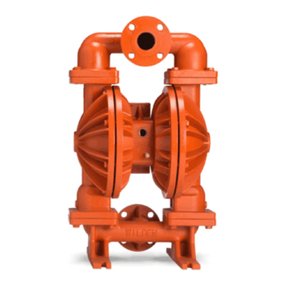
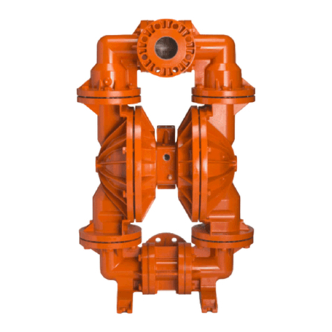
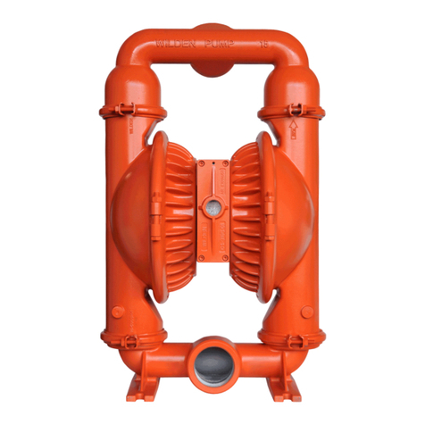
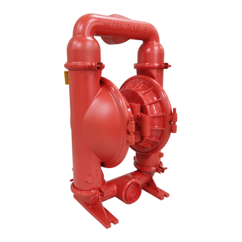
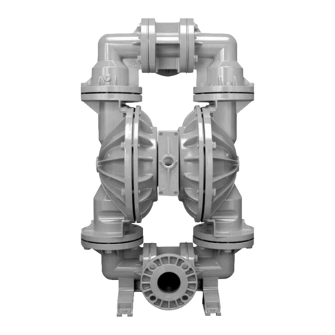
The Mode T4 P astic pump has a 3.81 cm (11⁄2") inet and 3.81
cm (11⁄2") out et and is designed for fows to 306.6 pm (81 gpm).
A variety of diaphragms, va ve ba s, va ve seats, and
O-rings are avaiab e to satisfy temperature, chemica compati-
bi ity, abrasion and f ex concerns.
The suction pipe size shou d be at east 3.81 cm (11⁄2") diameter
or arger if highy viscous materia is being pumped.The suction
hose must be non-co apsibe, reinforced type as the T4 is capa-
be of pu ing a high vacuum.Discharge piping shou d be at east
3.81 cm (11⁄2"); arger diameter can be used to reduce friction
osses.It is critica that a fittings and connections are airtight or
a reduction or oss of pump suction capabi ity wi resu t.
For T4 Champ mode s, Widen offers 150 b. standard or metric
f anges. The fo owing detai s shoud be noted when mating
these to pipe works:
• A 60–80 shore gasket that covers the entire fange face
shou d be used.
• The gasket shou d be between .075" and .175" thickness.
• Mating fanges with f at as opposed to raised surfaces shou d
be used for proper mechanica sea ing.
• The f anges shoud be tightened to a minimum of 6.8 m-N (5
ft.- bs.) but no more than 13.5 m-N (10 ft.- bs.).
A non-raised surfaced-fange adapter shoud be uti ized when
mating to the pump’s in et and discharge manifods for proper
sea ing.
INSTALLATION: Months of carefu p anning, study, and se ec-
tion efforts can resu t in unsatisfactory pump performance if
insta ation detai s are eft to chance.
Premature fai ure and ong term dissatisfaction can be avoided
if reasonab e care is exercised throughout the insta ation
process.
LOCATION: Noise, safety, and other ogistica factors usua y
dictate that “uti ity” equipment be situated away from the produc-
tion f oor.Mutipe insta ations with conf icting requirements can
resu t in congestion of utiity areas, eaving few choices for siting
of additiona pumps.
Within the framework of these and other existing conditions,
every pump shou d be ocated in such a way that four key
factors are ba anced against each other to maximum advan-
tage.
1. ACCESS: First of a , the ocation shou d be accessib e. If it’s
easy to reach the pump, maintenance personne wi have an
easier time carrying out routine inspections and adjustments.
Shou d major repairs become necessary, ease of access can
p ay a key ro e in speeding the repair process and reducing tota
downtime.
2. AIR SUPPLY: Every pump ocation shou d have an air ine
arge enough to supp y the vo ume of air necessary to achieve
the desired pumping rate (see pump performance chart). Use
air pressure up to a maximum of 8.6 Bar (125 psi) depending
upon pumping requirements.The use of an air fi ter before the
pump wi ensure that the majority of any pipe ine contaminants
wi be eiminated.For best resuts, the pumps shoud use an air
fi ter, regu ator, and ubricator system.
3. ELEVATION: Se ecting a site that is we within the pump’s
suction ift capabi ity wi assure that oss-of-prime troubes wi
be eiminated. In addition, pump efficiency can be adversey
affected if proper attention is not given to e evation (see pump
performance chart).
4. PIPING: Fina determination of the pump site shou d not be
made unti the piping prob ems of each possib e ocation have
been eva uated. The impact of current and future insta ations
shou d be considered ahead of time to make sure that inadver-
tent restrictions are not created for any remaining sites.
The best choice possib e wi be a site invo ving the shortest and
the straightest hook-up of suction and discharge piping. Unnec-
essary e bows, bends, and fittings shoud be avoided.Pipe sizes
shou d be se ected so as to keep friction osses within practica
imits. A piping shoud be supported independent y of the
pump. In addition, it shou d ine up without p acing stress on the
pump fittings.
Expansion joints can be insta ed to aid in absorbing the forces
created by the natura reciprocating action of the pump. If the
pump is to be boted down to a so id foundation, a mounting pad
p aced between the pump and foundation wi assist in minimiz-
ing pump vibration.Fexibe connections between the pump and
rigid piping wi a so assist in minimizing pump vibration.If quick-
c osing vaves are insta ed at any point in the discharge system,
or if pu sation within a system becomes a probem, a surge
suppressor shou d be insta ed to protect the pump, piping and
gauges from surges and water hammer.
When pumps are insta ed in app ications invo ving f ooded
suction or suction head pressures, a gate va ve shou d be
insta ed in the suction ine to permit c osing of the ine for pump
service.
The T4 can be used in submersibe app ications on y when both
wetted and non-wetted portions are compatibe with the mater-
ia being pumped. If the pump is to be used in a submersib e
app ication, a hose shou d be attached to the pump’s air
exhaust and the exhaust air piped above the iquid eve .
If the pump is to be used in a se f-priming app ication, be sure
that a connections are airtight and that the suction ift is within
the pump’s abiity.Note:Materias of construction and eastomer
materia have an effect on suction ift parameters. P ease refer
to pump performance data.
Pumps in service with a positive suction head are most efficient
when in et pressure is imited to .5–.7 Bar (7–10 psig). Prema-
ture diaphragm fai ure may occur if positive suction is .8 Bar (11
psig) and higher.
THE MODEL T4 WILL PASS 4.8 mm (3⁄16") SOLIDS. WHEN-
EVER THE POSSIBILITY EXISTS THAT LARGER SOLID
OBJECTS MAY BE SUCKED INTO THE PUMP, A STRAINER
SHOULD BE USED ON THE SUCTION LINE.
CAUTION: DO NOT EXCEED 8.6 BAR (125 PSIG) AIR
SUPPLY PRESSURE.
PUMPS SHOULD BE THOROUGHLY FLUSHED WITH
WATER BEFORE INSTALLING INTO PROCESS LINES. FDA
AND USDA PUMPS SHOULD BE CLEANED AND/OR SANI-
TIZED BEFORE USE ON EDIBLE PRODUCTS.
BLOW OUT AIR LINE FOR 10 TO 20 SECONDS BEFORE
ATTACHING TO PUMP TO MAKE SURE ALL PIPE LINE
DEBRIS IS CLEAR. ALWAYS USE AN IN-LINE AIR
FILTER.


