INSTALLATION AND
OPERATION MANUAL
PAGE 1
© Rev. 9/2022
1.800.428.4065 TOLL FREE
| www.willoughby-ind.com
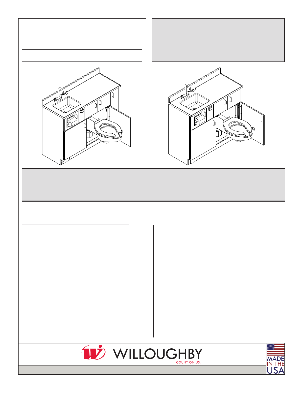
WH-1700
MODELS:
WH-1700 and WH-1750
Patient Care Units
TABLE OF CONTENTS
PRE-INSTALLATION INFORMATION....................... 3
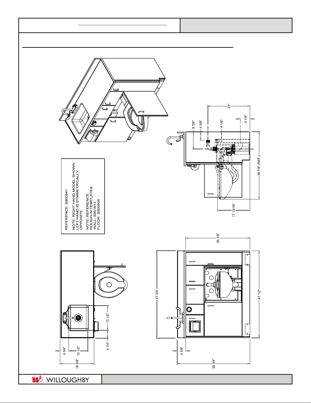
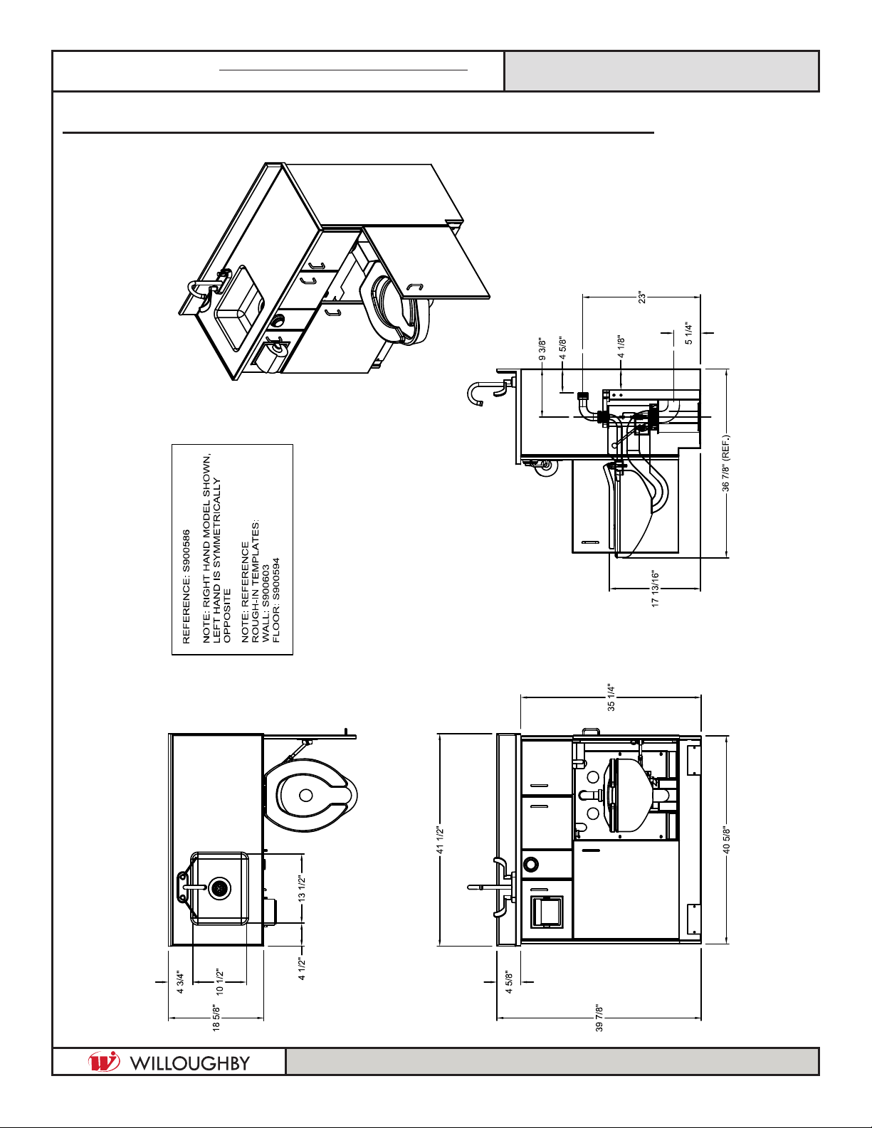
PHYSICAL DIMENSIONS .......................................... 4
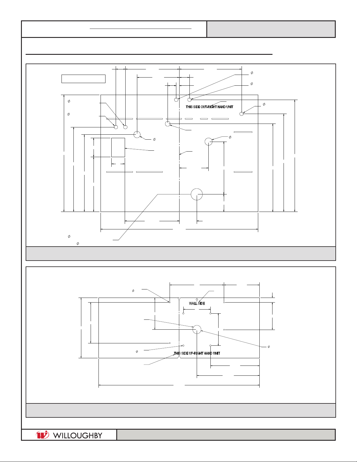
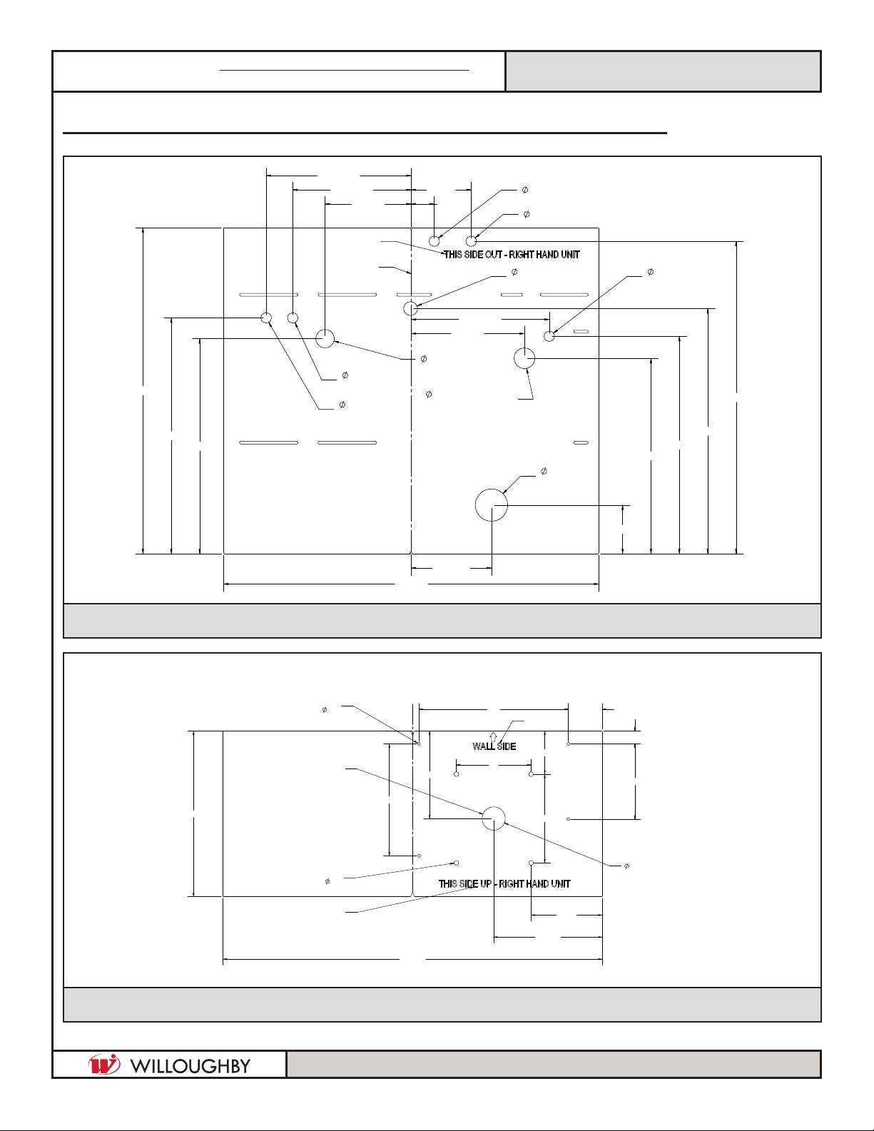
ROUGH-IN DIMENSIONS ........................................ 6
CHECKING CONTENTS............................................ 8
INSTALLATION INSTRUCTIONS .................................
Step 1: Unpack the WH-1700/1750.............10
Step 2: Install the Anchors .................................10
Step 3: Install the Toilet and
Waste Connections...............................11
Step 4: Install the Vacuum Breaker..................11
Step 5: Install the WH-1700/
WH-1750 Cabinet................................12
Step 6: Install the Solid Surface Lavatory
Top with Integral Bowl..........................12
Step 7: Install Faucet and Connect
Water Supply ........................................12
Step 8: Completing Installation ........................13
Step 9: Install and Adjust the Door Linkage...13
CARE AND MAINTENANCE ...................................14
DETAIL DRAWINGS......................................................
Swivel Toilet Assembly-L H1490-0084.......15
Swivel Toilet Assembly-R H1490-0085 ......16
WARRANTY..............................................................17
WILLOUGHBY
HEALTHCARE
PATIENT CARE UNITS
WH-1750