manuals.online logo
Brands
  1. Home
  2. •
  3. Brands
  4. •
  5. Wilmette Lighting
  6. •
  7. Transformer
  8. •
  9. Wilmette Lighting 600AT600 User manual

Wilmette Lighting 600AT600 User manual

1
Installation Instructions for 960AT122C
12V Dual Feed Remote Magnetic Transformer 600AT600_ 1.4
W I L M E T T E L I G H T I N G
COMPANY
TRANSFORMERS
GENERAL PRODUCT INFORMATION:
This product is ETL listed and suitable only for indoor dry
locations and approved for use at any height above the finished
floor.
A typical installation is shown. Specific installation must be in
accordance with the local electrical codes.
This product may be dimmed with a low voltage magnetic
dimmer. The dimmer must be derated as indicated by the dimmer
manufacturer.
This product is intended for use with Wilmette Lighting low
voltage lighting systems only.
During installation, make sure all power connections are tight.
Read all instructions thoroughly. Read "Important Safety
Information" on page 4 before proceeding with the installation.
C AUTION — RISK OF FIRE
This product requires installation by a qualified
electrician. Before installing be sure to read all
instructions and TURN THE POWER TO THE
ELECTRICAL BOX OFF.
2
NOTE: This type of low voltage wiring is for Wilmette
Lighting dual power feed MonoRail (two posts) system.
COMXX1X2X3X4
HOT1
COM2
HOT2
COM1
120 VOLT NEUTRAL
POWER LINE WIRE
120 VOLT HOT
POWER LINE WIRE
FROM TRANSFORMER
TO POWER FEED CANOPY
ELECTRICAL
POWER FEED BOX
COM2
HOT2
COM1
COMYY1Y2Y3Y4
120 VOLT BLACK
TRANSFORMER WIRE
120 VOLT WHITE
TRANSFORMER WIRE
TYPICAL
WIRE NUT
HOT1
1A
2
A
3456
9
10
3
Remove transformer cover by loosening the two Phillips
screws on the side of the transformer.
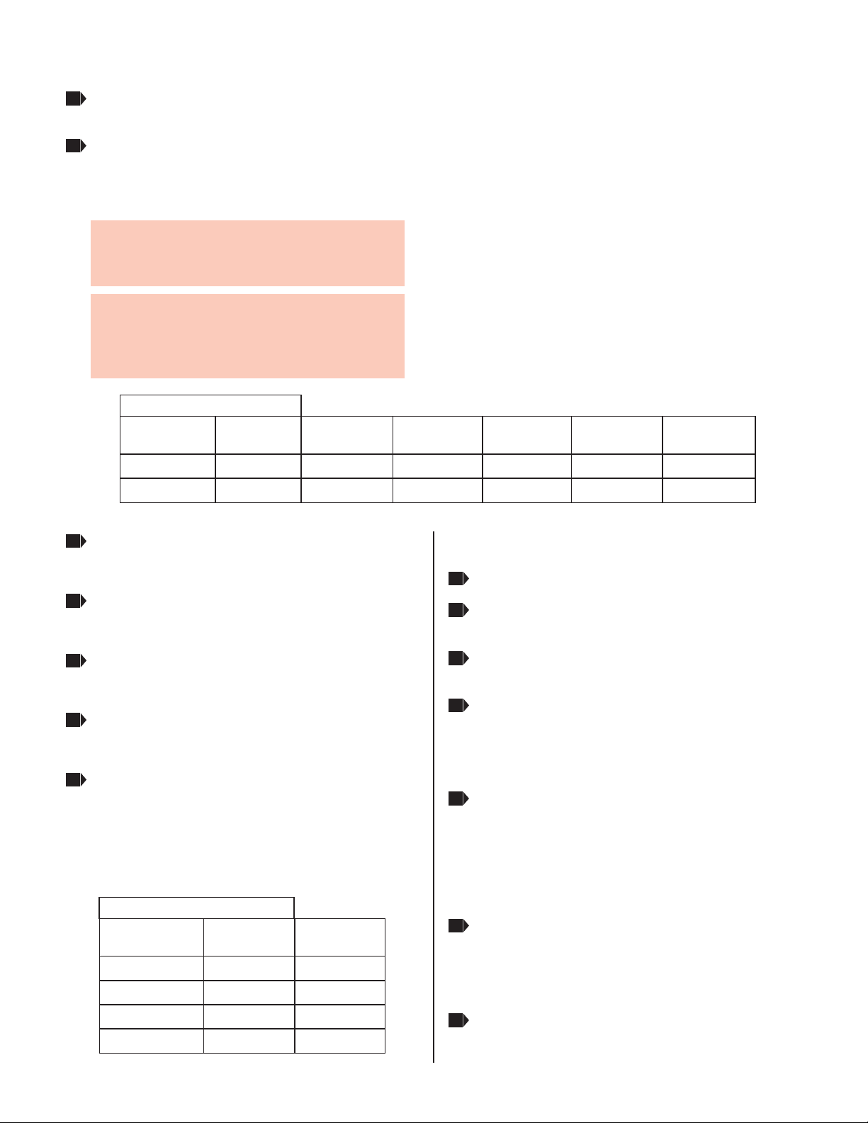
Install low voltage wires from the transformer to the
electrical power feed box to which the power feed canopy
will be attached. For best performance, use the wire size
from the voltage drop chart below.
Connect the 12 Volt Low Voltage Wires
NOTE: Other wire sizes that comply with electrical code
can be used, but may result in an increased voltage drop
and reduced lamp intensity.
NOTE: The THHN wire sizes are for 3% drop in voltage
based on 300 watt loads. Lengths are the distance from
the transformer to the system power feed connector
(Dimension ).
PRIMARY POWER
LINE VOLTAGE
105 - 109
TERMINAL TAP CHART
110 - 114
115 - 120
121 - 125
TERMINAL TAP
TO BE USED
X4
X3
X2
X1
Check The System
After installing the entire low voltage system, if the lamps
have low intensity, then measure the voltage at the fixture
closest to the power feed contacts with a voltmeter. The
system must be at least 80% loaded and the voltmeter
should read between 11V - 12V ~AC. If the voltage does
not fall in this range, call Wilmette Lighting "Technical
Support" at 847-410-4606.
Operate the system for five minutes. On the low voltage
side, all electrical connection spots should be cool to the
touch. If a connection is hot to the touch, retighten the
connection and check to ensure that the temperature
decreases.
Replace the transformer cover and tighten the two Phillips
screws on the sides of the transformer.
Insertonelowvoltagewireintothe"COMX"terminal
andtightenthescrewfirmly.Markthislowvoltagewire
intheelectricalpowerfeedboxas"COM1".
Insertthesecondlowvoltagewireintothe"X2"terminal
tap(default)andtightenthescrewfirmly.Markthislow
voltagewireintheelectricalpowerfeedboxas"HOT1".
Insertthethirdlowvoltagewireinto"COMY"terminal
andtightenthescrewfirmly.Markthislowvoltagewire
intheelectricalpowerfeedboxas"COM2".
Insertthefourthlowvoltagewireintothe"Y2"terminal
tap(default)andtightenthescrewfirmly.Markthislow
voltagewireintheelectricalpowerfeedboxas"HOT2".
Measurethevoltageattheprimarypowerlinecoming
intothetransformer.Ifthevoltageisnotintherangeof
115-120volt,thenpicktheproperterminaltapusing
the"TerminalTapChart"toreconnectthesecondand
fourthlowvoltagewires.
TERMINAL TAP
TO BE USED
Y4
Y3
Y2
Y1
Connect the 120 Volt Wires
Turn off the electrical power at panel.
Connect the 120V black transformer wire to the hot power
line wire with a wire nut.
Connect the 120V white transformer wire to the neutral
power line wire with a wire nut.
Turn on the electrical power at panel.
TRANSFORMER
WATTAGE
WIRE SIZE
FOR 5 FT
WIRE SIZE
FOR 6-15 FT
WIRE SIZE
FOR 16-20 FT
WIRE SIZE
FOR 21-40 FT
WIRE SIZE
FOR 40-60 FT
WIRE SIZE
FOR 61-90 FT
250 WATT #6 GA #4 GA #2 GA #1 GA #2/0 GA#10 GA
VOLTAGE DROP CHART
300 WATT #6 GA #4 GA #1 GA #1/0 GA #3/0 GA#10 GA
A
2
1
3
4
5
6
7
8
9
10
11
2
1
3
4
SAVE THESE INSTRUCTIONS!
Important Safety Information
Do not conceal or extend bus bar conductors through a building
wall.
Do not install this lighting system in a damp or wet location.
To reduce the risk of fire and burns, do not install this lighting
system where the uninsulated open bus bar conductors can be
shorted or contact any conductive materials.
To reduce the risk of the system overheating and possibly causing
a fire, make sure all the connections are tight.
Do not install fixture assemblies closer than six inches to curtains
or similarly combustible materials.
Turn the electrical power off before modifying the lighting system
in any way.
The fixtures used with the system must be identified to be used
with the corresponding system.
Minimum volume of the electrical box must be 6 cubic inches (98
cubic centimeter).
The system is "ETL" listed for USA and Canada only when all the
products used are supplied by Wilmette Lighting.
It is important to wire the remote transformer for the system as
described in these instructions.
Load the circuit of the remote transformers to no more than the
maximum rated capacity as specified.
7400LinderAve,Skokie,IL60077
847.410.4400
www.wilmettelighting.com
W I L M E T T E L I G H T I N G
COMPANY
©2008WilmetteLightingCompany.Allrightsreserved.The"WilmetteLightingCompany"
graphicisaregisteredtrademarkofWilmetteLightingCompany.WilmetteLightingCompany
reservestherighttochangespecificationsforproductimprovementswithoutnotification.
A Generation Brands Company

Popular Transformer manuals by other brands

JUNO Juno T537QJ installation instructions

JUNO

JUNO Juno T537QJ installation instructions

MGM 600V CLASS DRY Application, Installation, Operation, and Maintenance Manual

MGM

MGM 600V CLASS DRY Application, Installation, Operation, and Maintenance Manual

ELEQ TQ30 installation guide

ELEQ

ELEQ TQ30 installation guide

DAELIM GREEN EP TECH Operation & maintenance manual

DAELIM

DAELIM GREEN EP TECH Operation & maintenance manual

Hasbro Oil Slick 83626 instructions

Hasbro

Hasbro Oil Slick 83626 instructions

Monacor Security TVI-100 manual

Monacor

Monacor Security TVI-100 manual

Jobsite BT-HDDA Installation and user guide

Jobsite

Jobsite BT-HDDA Installation and user guide

Monacor FGA-30 manual

Monacor

Monacor FGA-30 manual

Airsafe ITF Operation manual

Airsafe

Airsafe ITF Operation manual

Hasbro Rally Rocket Bumblebee 83783 instructions

Hasbro

Hasbro Rally Rocket Bumblebee 83783 instructions

GE OTEF-72 instruction manual

GE

GE OTEF-72 instruction manual

Nordson Coolwave 2 T3 instruction sheet

Nordson

Nordson Coolwave 2 T3 instruction sheet

CyberPower OL5KSTF Installation and operation manual

CyberPower

CyberPower OL5KSTF Installation and operation manual

Lutron Electronics Sivoia QED SV-100SF-JBOX installation instructions

Lutron Electronics

Lutron Electronics Sivoia QED SV-100SF-JBOX installation instructions

Fluke EI-162BN user manual

Fluke

Fluke EI-162BN user manual

Camille Bauer SIRAX CT3 Series operating manual

Camille Bauer

Camille Bauer SIRAX CT3 Series operating manual

Digital Acoustics COMTR4070-WA Getting started guide

Digital Acoustics

Digital Acoustics COMTR4070-WA Getting started guide

Jobsite BT-SV Installation and user guide

Jobsite

Jobsite BT-SV Installation and user guide

manuals.online logo
manuals.online logoBrands
  • About & Mission
  • Contact us
  • Privacy Policy
  • Terms and Conditions

Copyright 2025 Manuals.Online. All Rights Reserved.