Wilo CAT 5 MHI Series User manual

CAT 5 MHI(E)
EN Installation and operating instructions
2819142 CAT5 1MHI202/PS-EM 29992800 CAT5 1MHI202/EC-EM-2
2819143 CAT5 1MHI203/PS-EM 29992801 CAT5 1MHI203/EC-EM-2
2819144 CAT5 1MHI204/PS-EM 29992802 CAT5 1MHI204/EC-EM-2
2819145 CAT5 1MHI205/PS-EM 29992803 CAT5 1MHI205/EC-EM-2
2819146 CAT5 1MHI206/PS-EM 29992804 CAT5 1MHI206/EC-EM-2
2819147 CAT5 1MHI402/PS-EM 29992805 CAT5 1MHI402/EC-EM-2
2819148 CAT5 1MHI403/PS-EM 29992806 CAT5 1MHI403/EC-EM-2
2819149 CAT5 1MHI404/PS-EM 29992807 CAT5 1MHI404/EC-EM-2
2819150 CAT5 1MHI405/PS-EM 29992808 CAT5 1MHI405/EC-EM-2
2819151 CAT5 1MHI406/PS-EM 29992809 CAT5 1MHI406/EC-EM-2
2819152 CAT5 1MHIE205/DM
2819153 CAT5 1MHIE205/EM
2819280 CAT5 1MHIE803/DM
2819336 CAT5 1MHIE403/EM
29991772 CAT5 1MHIE 406/DM
CD_TE0059 rev00

2
Contents
Page
1) General 3
2) Safety Instructions
2.1 Symbols and Signals 3
2.2 Modication and Spares 3
3) Transport and Storage 3
4) Description and Operation
4.1 MHI PS-EM (Single Phase Fixed Speed) 3
4.1.1 Operation Modes 3
4.1.2 Operating Features 3
4.2 MHIE DM (Three Phase Variable Speed) 4
4.2.1 Operation Modes 4
4.2.2 Operating Features 4
4.3 MHI EC-EM (Single Phase Variable Speed) 4
4.3.1 Operation Modes 4
4.3.2 Operating Features 4
4.4 MHIE EM (Single Phase Variable Speed) 4
4.4.1 Operation Modes 4
4.4.2 Operating Features 4
5) Installation
5.1 Hydraulic Connections 4
5.2 Electrical Connections 4
6) Commissioning
6.1 Commissioning 5
6.2 Maintenance 5
7) Warranty 5
8) Figures
Fig 1 MHI PS-EM Electrical Connections 6
Fig 2 MHIE DM Electrical Connections 6
Fig 3 MHI EC-EM Electrical Connections 7
FIg 4 MHIE EM Electrical Connections 7
Fig 5 System General Arrangement 8
Fig 6 MHI PS-EM General Arangement 8
Fig 7 MHIE DM General Arrangement 9
Fig 8 MHIE EM Controls 9
Fig 9 MHI EC-EM General Arrangement 10
9) Tables
Table 1 EC-EM Drive User Interface 10
Table 2 EC-EM Settings Menu 11
Table 3 Drive Fault Codes 12
10) Spares
Spares 1 PS-EM & DM 13
Spares 2 EC-EM-2 14
11) Certicate of Conformity 15

3
1 General
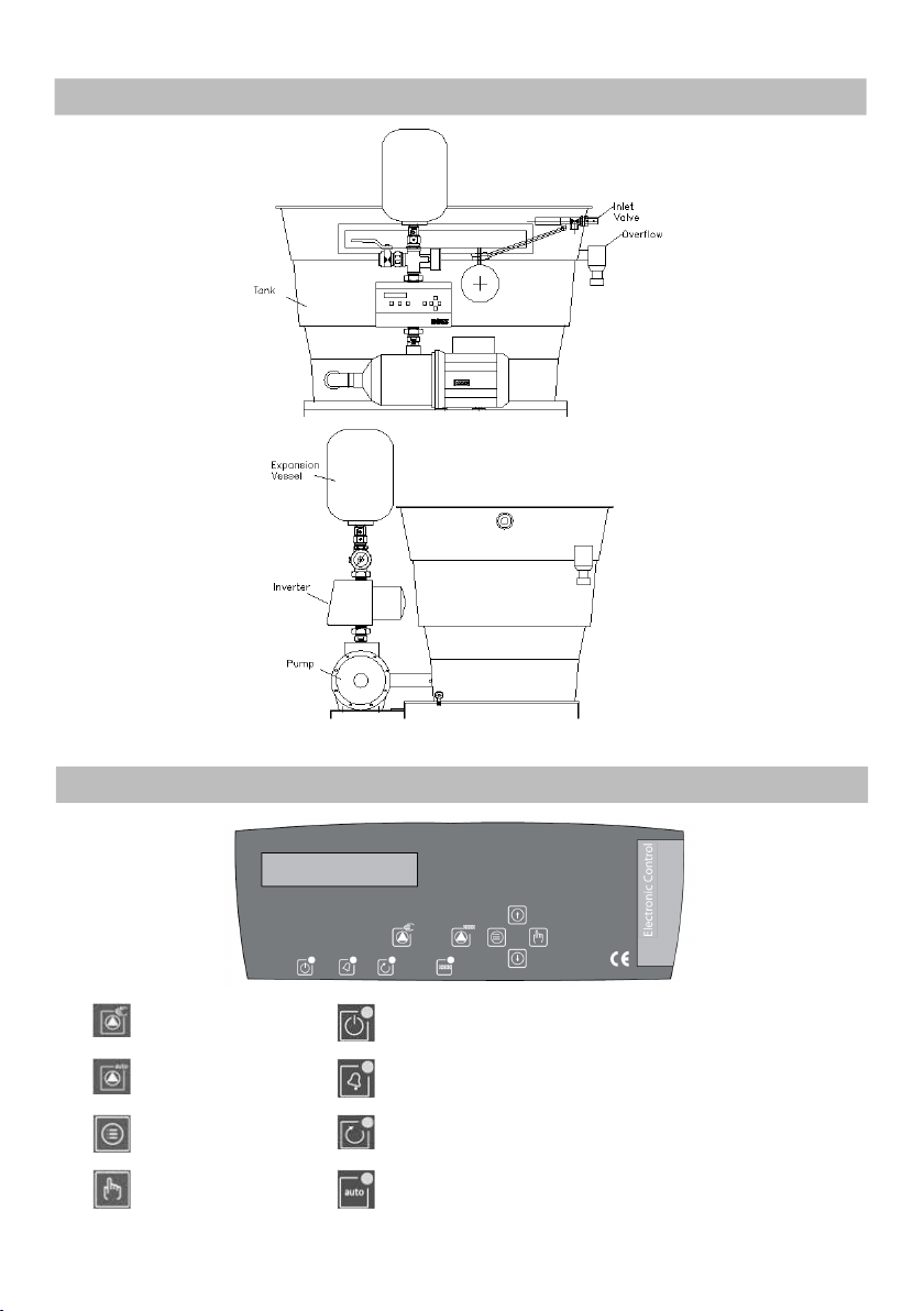
The CAT 5 booster set is a pressure boosting
system designed for raising the pressure of water
for wash down requirements. Using a single pump
xed or variable speed booster, 115 litre actual
capacity tank with category 5 backow prevention
via an AB airgap.
ATTENTION! Installation and commissioning by
qualied personnel only!
NOTE – An onsite audit must be completed once
installed to ensure there are no contributing
factors that may compromise the air gap (ie.
foaming, splashing)
2 Safety
Any works carried out on CAT 5 booster sets must
be completed by a qualied person. Failure to
comply to any of the information in this manual
may cause potential hazards to people and the
environment and may void the warranty.
Operators must be fully aware of all functions of
the boosterset and any risks associated. For more
information on training please contact Wilo Ph:
01283 523 000
WARNING! Local regulations must be complied
to when installing and maintaining the booster
set
2.1 Symbols and Signals
DANGER! Extremely dangerous situation. Non-
observance could cause death or serious injuries.
WARNING! The user may suffer from injuries
(serious). The mention of warning involves that
personal (serious) injuries may happen when
precautions are not observed.
ATTENTION! Damage could be caused to the
pump or installation. The mention of attention
is used to indicate that by ignoring the relevant
safety instructions, damage could be caused to
the pump or its operation.
NOTE - Useful remark for product handling. Any
possible difculty is mentioned.
2.2 Modication and Spare Parts
Modications to the booster are prohibited and
will invalidate the warranty. Wilo Approved spares
must be used at all times. For information on
spares see Table 4 of this manual
3 Transport and Storage
CAT 5 booster must always be transported
by pallet and moved with appropriate lifting
equipment. Booster must be stored in a dry
environment between –25 °C to +55 °C.
NOTE – If stored for future installation the lm
wrapping must not be removed and must be
stored in a dry environment
4 Description and Operation
4.1 MHI PS-EM (Single Phase Fixed Speed)
4.1.1 Operating Mode
CAT 5 PS-EM is a xed speed booster set which
is controlled with a Hand Off Auto (HOA) box via
a pressure switch. When the switch is turned to
Hand Mode the set will run at full speed constantly
and will not turn off. When the switch is turned to
Auto Mode the set will run until the pressure set
on the pressure switch has been reached. Once the
pressure has been achieved the set will run until
the programmable timer times out
4.1.2 Operating Features
•Programmable pressure switch – Sets the
pressure at which the timer starts via dials on the
front of the switch (Fig 6)
•Programmable timer – Sets the length of time the
booster will run once the set pressure has been
achieved. Programmable in the HOA box (Fig 6)
•Low water cut out switch – Turns the booster off
instantly once the water level drops below a set
level to stop air from entering the pump (Fig 1)
•Volt Free Contacts (VFC) – Normally open and
normally closed contacts signal if the pump has
tripped under high current (Fig 1)
NOTE – Programmable timer is inside the HOA
box and is factory set at 120 seconds to reduce
start/stop frequency of the set.

4
4.2 MHIE DM (Three Phase Variable Speed)
4.2.1 Operating Mode
CAT 5 DM is a variable speed booster set which is
controlled via an integrated motor mounted drive
and pressure transducer. Once the pressure is set
on the drive the speed of the pump will ramp up
and down according to the demand of the system
(see pump manual for the setting of the system
pressure)
NOTE – No ow cut off time can be changed in
the drive via menu 5.2.7.0 and is factory set at
30 seconds
4.2.2 Operating Features
•0-20mA pressure transducer monitors system
pressure
•SBM Volt Free Contact (VFC) – Can be congured
to switch on power up or run (see menu 4.7.6.0)
•SSM Volt Free Contact (VFC) – Switches when
pump goes into fault conditions
•Low water cut out switch – Turns the booster off
instantly once the water level drops below a set
level to stop air from entering the pump
4.3 MHI EC-EM (Single Phase Variable Speed)
4.3.1 Operating Mode
CAT 5 EC-EM is a variable speed booster set
which is controlled via a water cooled inverter.
The pressure is set in the drive by holding down
the menu button (Table 1) and cycling through
the drive settings by pressing the ‘Enter’ button
and changing the settings with the up and down
arrows. For full programmable settings see Table
2. Once the pressure is set on the drive press the
‘Automatic Mode’ button and the speed of the
pump will ramp up and down according to the
demand of the system.
To run the pumps at a constant 50Hz press and
hold the ‘Manual Mode’ button
4.3.2 Operating Features
•Low water cut out switch – Turns the booster off
instantly once the water level drops below a set
level to stop air from entering the pump
•Programmable electronic menu with alarm log
and run timer (Table 2)
4.4 MHIE-EM (Single Phase Variable Speed)
4.4.1 Operating Mode
MHIE-EM is a variable speed booster set which is
controlled via an integrated motor mounted drive
and pressure transducer. System pressure is set
via the variable speed dial on the side of the motor
(Fig8). System pressure is approximately 1 bar for
every 10% on the dial. Set the system pressure by
starting at 0% on the dial and slowly raising until
required setpoint is reached.
ATTENTION! Test pressure setpoint, by isolating
the system via isolation valve to reduce the risk
of over pressure in the system
4.4.2 Operating Features
•Programmable electronic menu with alarm log
and run timer (Table 2)
•Pump fail volt free contact 230V 1A (Fig4)
5 Installation
5.1 Hydraulic Connections (Fig5)
The mains water is connected directly onto the ½”
male BSP thread equilibrium ball valve. The booster
discharge is connected directly onto the isolation
valve which has a 1” female BSP thread. All CAT
5 sets must be tted with the supplied 8 litre
diaphragm pressure vessel onto the vessel valve
provided next to the isolation valve. Once the tank
is lled the pump must be properly vented before
use.
ATTENTION! Connections must be made
according to local water authority regulations
5.2 Electrical Connections (Fig1-4)
Please use the correct wiring diagram provided
with the booster for connection of mains voltage.
Pay close attention to the terminals used and that
the correct voltage is applied. Failure to do so may
cause damage to pump or drives and will void the
warranty.
DANGER! The electrical connections and testing
must be carried out by a qualied electrician and
in accordance with locally applicable standard
specications.

5
6 Commissioning
6.1 Commissioning
It is recommended that the rst installation is
commissioned by Wilo customer service. Contact
Before switching on for the rst time check
the customers wiring is compliant with local
regulations and is t for purpose.
Check the pipe connections are stress free
Fill the storage tank and visually check for leaks
Close discharge valve and turn power on
Run pump against closed valve until pump
switches off. This may require the adjustment of
the pressure switch
Open system valve partially and allow unit to ll
the system and switch off.
Ensure storage tank ll is adequate for the
system, Do not allow pump to run dry, this may
cause damage to the mechanical seal and other
components.
Once system is lled fully open the system valve.
DANGER! Risk of fatal injury! Tighten all
connection terminals prior to commissioning!
6.2 Maintenance
To ensure maximum reliability in operation we
recommend that the expansion vessel is checked
at least annually. This may require more frequent
checks if the unit is subject to higher frequencies
of use.
Checks should be made on condition of stored
water tank and must be debris free.
Checks should be made on switching frequencies
and operation.
The general safety instructions must be observed
when carrying out any remedial work. Please
follow the Installation and Operation manual for
pump and control unit.
ATTENTION! Any maintenance must be
completed by a trained and competent person.
Any damage to the booster could void warranty
if this is not adhered to
7 Warranty
WILO reserve the right to inspect an installation
to verify that the equipment has been installed in
accordance with the written instructions. The full
warranty document is downloadable at www.wilo.
com/gb/en/downloads. Click on local information
then downloads. Before requesting a site visit, the
following information must be available to the
service team:
• Article number of the equipment
• A purchase order to cover the work in the event
that no manufacturing defect is found.
• A site contact name and number
• A FULL description of the alleged fault

6
Fig. 1 - MHI PS-EM Electrical Connections
Fig. 2 - MHIE-DM Electrical Connections
8) Figures

7
Fig. 3 - MHI EC-EM
Fig. 4 MHIE EM Electrical Connections

8
Fig. 5 General Arrangement (Hydraulic)
Fig. 6 PS-EM Layout

9
Fig. 7 MHIE-EM/DM Layout
Fig. 8 MHIE-EM Controls

10
Manual Mode Inverter On (Green LED)
Automac Mode Alarm (Red LED)
Menu Pump Running (Yellow LED)
Enter Pump in Automac Mode (Green LED)
Table 1 Driver User Interface (EC-EM)
Fig. 9 MHI EC-EM Layout

11
Table 2 Settings Menu (EC-EM)
MENU SETTINGS FACTORY UNIT
Language Language select English
I max Set the maximum current rang of the pumps *Amps
Rotaon Sense Change the rotaon of the motors Clockwise
Min Speed Minimum running speed of the motor 15 Hz
Dry Run Prot Turn on or o the dry running protecon Yes
Pressure Seng System pressure that you want the booster to achieve ** Bar
Start Delta Dierence in pressure before the pumps start 0.3 Bar
Time Before Stop Time the pumps will run once the pressure has been
reached at no ow 15 Sec
MENU HISTORIC
Running Time Total pump running hours Hrs
Pump Cycles Total number of pump cycles (one cycle = one run
and stop)
Power On Number of mes the drive has been powered on
Max Pressure Maximum pressure of the installaon Bar
Short Circuit Total number of short circuit alarms
Over Current Total number over current alarms
Over Temp. Total number of over temperature alarms
Dry Run Total number of dry run alarms
*Dependant on motor size
** Dependant on booster type (see test sheet)

12
Table 3 Drive Fault Codes
ERROR CODE BOOSTER BEHAVIOUR TROUBLESHOOT
E011 DRY RUN
The controller starts the pump every
30 minutes over 24 hours. If dry
running remains, it switches off the
pump.
Check the hydraulic supply.
If a set point pressure higher than the
pressure the pump can deliver is pro-
grammed, the controller will consider it
as dry running.
E021 OVERLOAD
After the alarm detection the control-
ler will try 4 times to Check that the rotor is not locked.
start the pump. After these 4 trials
the pump is switched off.
Check the state of the fuses.. Check the input data in the controller
E025 DISCONNECT MOTOR Motor will not start.
Check the motor winding.
Check the supply cables.
Check that the Imax is not set to off in
the menu (Table 2)
E040 P SENSOR DEFFECT The controller stops. Contact the technical service depart-
ment.
E031 OVER T°
If the temperature is too high, the
controller will stop the motor from
running.
Check that the water temperature does
not exceed 40°C.
Check that the ambient temperature
does not exceed 50°C.
E023 SHT CIRCUIT
After the alarm detection the
controller will try 4 times to start the
pump. After these 4 trials the pump is
switched off.
Check the motor connections and wind-
ings. If the problem remains contact the
manufacturer.
E071 EEPROM
If the controller detects a defect on
its internal memory this error will be
displayed.
Contact the technical service depart-
ment.
E005 HIGH VOLTAGE
If the controller detects an overvolt-
age, it stops over some seconds and
then starts again.
Check the controller supply voltage.
E004 If the controller detects an under
voltage, it stops the pumps. Check the controller supply voltage.
LOW VOLTAGE
[WHITE SCREEN] No function and nothing on the
screen.
Check the controller supply voltage and
circuit breakers in (Fig 1).
Check the 20A fuses

13
Spares 1 PS-EM & DM
2819142 CAT5
1MHI202/PS-EM
2819143 CAT5
1MHI203/PS-EM
2819144 CAT5
1MHI204/PS-EM
2819145 CAT5
1MHI205/PS-EM
2819146 CAT5
1MHI206/PS-EM
2819147 CAT5
1MHI402/PS-EM
2819148 CAT5
1MHI403/PS-EM
2819149 CAT5
1MHI404/PS-EM
2819150 CAT5
1MHI405/PS-EM
2819151 CAT5
1MHI406/PS-EM
2819152 CAT5
1MHIE205/DM
2819153 CAT5
1MHIE205/EM
2819336 CAT5
1MHIE403/EM
29991772 CAT5
1MHIE406/DM
2819280 CAT5
1MHIE803/DM
Pumps
4024282 MHi202-1/E/1-230
4024284 MHi203-1/E/1-230
4024286 MHi204-1/E/1-230
4024288 MHi205-1/E/1-230
4024290 MHi206-1/E/1-230
4024292 MHi402-1/E/1-230
4024294 MHi403-1/E/1-230
4024296 MHi404-1/E/1-230
4024298 MHi405-1/E/1-230
4024300 MHi406-1/E/1-230
4148406 MHIE205N-1/E/3
4073101 MHIE205 1PH M2
4073103 MHIE403 1PH M2
4148418 MHIE406N-1/E/3
4148424 MHIE 803 N-1/E/3
Vessel
2815472 8L Expansion Vessel
Controls
2818634 HOA BOX 3-5A
2818635 HOA BOX 4.5-7A
2818636 HOA BOX 6-10A
2818736 Pressure Switch
2085909 Pressure Sensor
2818575 Low Water Switch
4160334 Water Cooled Inverter
Valves
2818409 1/2" Inlet Valve (oat inc.)
2819156 1" Isolation Valve
2520853 3/4" Vessel Valve
2818056 1” Non Return Valve

14
Spares 2 EC-EM
29992800 CAT5
1MHI202/EC-EM-2
29992801 CAT5
1MHI203/EC-EM-2
29992802 CAT5
1MHI204/EC-EM-2
29992803 CAT5
1MHI205/EC-EM-2
29992804 CAT5
1MHI206/EC-EM-2
29992805 CAT5
1MHI402/EC-EM-2
29992806 CAT5
1MHI403/EC-EM-2
29992807 CAT5
1MHI404/EC-EM-2
29992808 CAT5
1MHI405/EC-EM-2
29992809 CAT5
1MHI406/EC-EM-2
Pumps
4024283 MHi202-1/E/3
4024285 MHi203-1/E/3
4024287 MHi204-1/E/3
4210718 MHi205-1/E/3
4210722 MHi206-1/E/3
4024293 MHi402-1/E/3
4024295 MHi403-1/E/3
4210725 MHi404-1/E/3
4210732 MHi405-1/E/3
4210735 MHi406-1/E/3
Vessel
2815472 8L Expansion Vessel
Controls
2818575 Low Water Switch
4160334 Water Cooled Inverter
2818472 Isolator
Valves
2818409 1/2" Inlet Valve (oat inc.)
2819156 1" Isolation Valve
2520853 3/4" Vessel Valve
2818056 1” Non Return Valve

15
Document Number: FMPRD012 rev02 07/09/2019
CAT 5MHI… PS/EM
CAT 5MHI… EC2/EM
CAT 5MHIE… DM
CAT 5MHIE… EM/DM
EC - Declaration of conformity
Herewith, we declare that CAT 5MHI-E of the series
(The serial number is marked on the product site plant)
in its delivered state complies with the following relevant provisions:
EC-Machinery Directive
Low Voltage Directive
Electromagnetic Compatibility Directive
WEEE Directive
ROHS Directive
As well as following harmonized standards
If the above mentioned series are technically modified without our approval, this declaration
shall no longer be applicable
Authorized representative for the completion of the technical documentation:
EN 809:1998 +A1:2009
EN60204-1 +A1 2009
EN61000-6-3:2007 +A1:2011
EN61000-6-2:2005
WILO UK
Centrum 100
Second Avenue
Burton-Upon-Trent
DE14 2WJ
Lee Tebbatt
Managing Director
2
nd
March 2020
2006 / 42 / EC
2014 / 30 / EU
2012 / 19 / EU
2014 / 35 / EU
2015 / 863 / EU

This manual suits for next models
51
Table of contents
Other Wilo Extender manuals