Applications
One of Wilson Audio’s most important criteria in speaker development is that a
speaker meets the accuracy and dynamic demands of studio monitoring, analytical hard-
ware and software evaluation, and, of course, critical music and theater soundtrack listen-
ing. The WATCH Center Series 2 has been designed to deliver all of the speed, dynamics,
and musical accuracy to satisfy even the most demanding music lovers.
The WATCH Center has been engineered to take full advantage of today’s multi-chan-
nel surround formats, including the latest AC-3 (Dolby Digital) and DTS (Digital Theater
Systems) formats.
It will provide years of satisfaction whether listening to two-channel audio, multi-
channel audio, or to the latest movie sound track.
Section 1.2 – WATCH Package
WATCH Center Series 2
Specifically designed to excel at center channel functions, WATCH Center is ex-
tremely dynamic with high sensitivity and
robust power handling. Unlike most cen-
ter channels, it provides listeners not only
with optimal on-axis response, but also
smooth, linear, off-axis performance. This
is, in part, a result of Wilson PDC (Propa-
gation Delay Correction) technology first
developed for the WAMM®and X-1 Grand
SLAMM®systems and later applied to the
rest of the Wilson Line. PDC allows for op-
timal tuning of a loudspeaker for various
listening distances and heights and gives listeners much greater control over their sound.
The WATCH Center Series 2 was designed from the ground up as a center channel.
It is not merely a standard speaker that was tipped onto its side. The Center channel was
voiced and optimized to truly represent dialogue for movies as well as music and vocals
when used in a multi-channel audio setup.
Of course, the WATCH Center Series 2 lives up to Wilson’s high standards of cutting
edge design, superior build quality, and stunning sonic performance. The WATCH Center
is available with a matching stand.
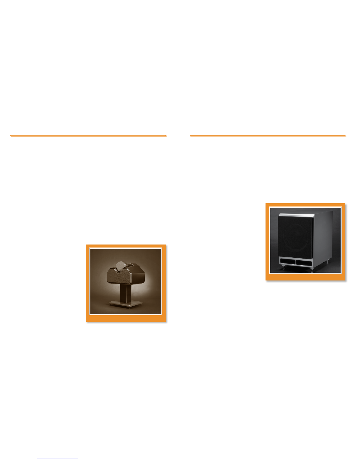
WATCH Dog Passive Subwoofer
The WATCH Dog passive subwoofer
is the culmination of over twenty years of
experience at Wilson Audio in building
high output, ultra-low distortion woofer
and subwoofer products. It was designed
to further extend and enhance the bottom
octave performance of music and theater
systems without compromising speed, tonal
accuracy, or phase coherency. The WATCH
Dog will seamlessly and coherently inte-
grate with any loudspeaker, whether you
are augmenting a two-channel system or
using the Dog as the LFE channel in a surround system.
WATCH Controller
Like other WATCH products, along with music system applications, the WATCH Dog
was designed to take advantage of today’s multi-channel formats. The unique tuneability
1312
Figure 1 - WATCH CenTer CHAnnel SerieS 2
Figure 2 - WATCH dOg PASSiVe SubWOOFer
W A T C H C enTer C HAnnel S erieS 2 O Wner’SM AnuAl
12
Wilson Audio Specialties
12
Wilson Audio Specialties
13
Wilson Audio Specialties
SeCTiOn 1 . 2 – W A T C H P ACkAge