Wilson Electronics weBoost DRIVE X FLEET User manual

ENGLISH
FRANÇAIS
Installation Guide
PROFESSIONAL VEHICLE CELL PHONE
SIGNAL BOOSTER KIT
DRIVE X FLEET
A WILSON ELECTRONICS BRAND
NEED HELP? weboost.ca 866.294.1660

______
Index
Package Contents 1
STEP 1-A: Drill Cable Entry Hole To Your Vehicle 2
STEP 1-B: Insert & Route Cable 4
STEP 1-C: Mount NMO Outside Antenna 5
STEP 2: Mount In-Vehicle Antenna 6
STEP 3: Wiring The Power Supply To Vehicle Battery 7
STEP 4: Connect Coax Cables To Booster 8
STEP 5: Connect Power Supply To Booster 9
Light Patterns 10
Troubleshooting 11
Safety Guidelines 12
Specifications 13
Warranty 14

DRIVE X FLEET PROFESSIONAL VEHICLE SIGNAL BOOSTER KIT 1
ENGLISH
________
Package
Contents
Drive X
Booster
& Bracket
Outside NMO
Antenna +
Connector
Mounting Cable
In-Vehicle
Antenna
Power
Supply
Optional Antenna
Extension Cable
Protective Tape
For Installation
O-Ring Lubricant
Packet

2PROFESSIONAL VEHICLE SIGNAL BOOSTER KIT DRIVE X FLEET
ENGLISH
______
Step 1-A: Drill Cable Entry
Hole To Your Vehicle
Identify a location for NMO Outside Antenna on the
top of your vehicle that is:
Near the center of the roof
At least 12 inches away from any other antennas
At least 6 inches away from any windows
(for best performance install on top of vehicle)
Do a ‘soft install’ before drilling the hole for the
cable entry.
Set up the system by routing the cable through
an open door or window, completing the setup
instructions, verifying the system works as desired,
and then drilling the hole.
6 in. away from windows
(including sunroofs)
Good NMO Outside
Antenna Placement

DRIVE X FLEET PROFESSIONAL VEHICLE SIGNAL BOOSTER KIT 3
ENGLISH
Place the protective tape on the
vehicle in the desired location.
Using a 3/4” hole saw, drill a
hole in the center of the
protective tape.
______
(STEP 1-A cont.)
After completing the ‘soft install’ and identifying NMO
Outside Antenna location:
protective tape
vehicle surface
protective tape
3/4” bit

4PROFESSIONAL VEHICLE SIGNAL BOOSTER KIT DRIVE X FLEET
ENGLISH
apply silicone grease
After hole has been drilled, insert NMO Mounting Cable
through (SMA connector end first) and remove collar.
Position threads of the cable mount above vehicle surface.
Apply included silicone grease to the o-ring on the collar
then screw the collar to the base mount. Ensure the mount is
centered in the hole and tighten with wrench.
screw collar
to base mount
For a professional installation, we recommend routing the cable
under the headliner and down through the side trim panel to
the desired booster location on the floor of the vehicle.
side trim panel
headliner
r
u
n
c
a
b
l
e
f
r
o
m
N
M
O
O
u
t
s
i
d
e
A
n
t
e
n
n
a
t
o
b
o
o
s
t
e
r
______
Step 1-B: Insert & Route Cable
remove
collar
insert through hole

DRIVE X FLEET PROFESSIONAL VEHICLE SIGNAL BOOSTER KIT 5
ENGLISH
Before attaching the antenna, apply a thin layer of silicone
grease to the threads, only, to the NMO mount and to the
o-ring on the antenna. Screw the antenna onto the NMO
mount and hand tighten into place.
hand tighten and make sure
gasket is touching vehicle
surface
screw on
NMO Antenna
______
Step 1-C: Mount NMO
Outside Antenna
apply silicone grease
NOTE: DO NOT apply silicone grease to the antenna pin contact surface.

6PROFESSIONAL VEHICLE SIGNAL BOOSTER KIT DRIVE X FLEET
ENGLISH
The location should be at least 18 inches but no more than
36 inches from where the cell phone device will be used.
Adhesive and Velcro® mounting options are included.
In-Vehicle Antenna
Identify a place to mount the In-Vehicle Antenna, either on
the side of the seat or on the dash and mount.
______
Step 2: Mount In-Vehicle
Antenna
clean surface of dash before attaching
adhesive strip
dash option
seat option
In-Vehicle
Antenna

DRIVE X FLEET PROFESSIONAL VEHICLE SIGNAL BOOSTER KIT 7
ENGLISH
Before connecting the power supply, disconnect the vehicle battery
leads to avoid any electrical shocks during installation.
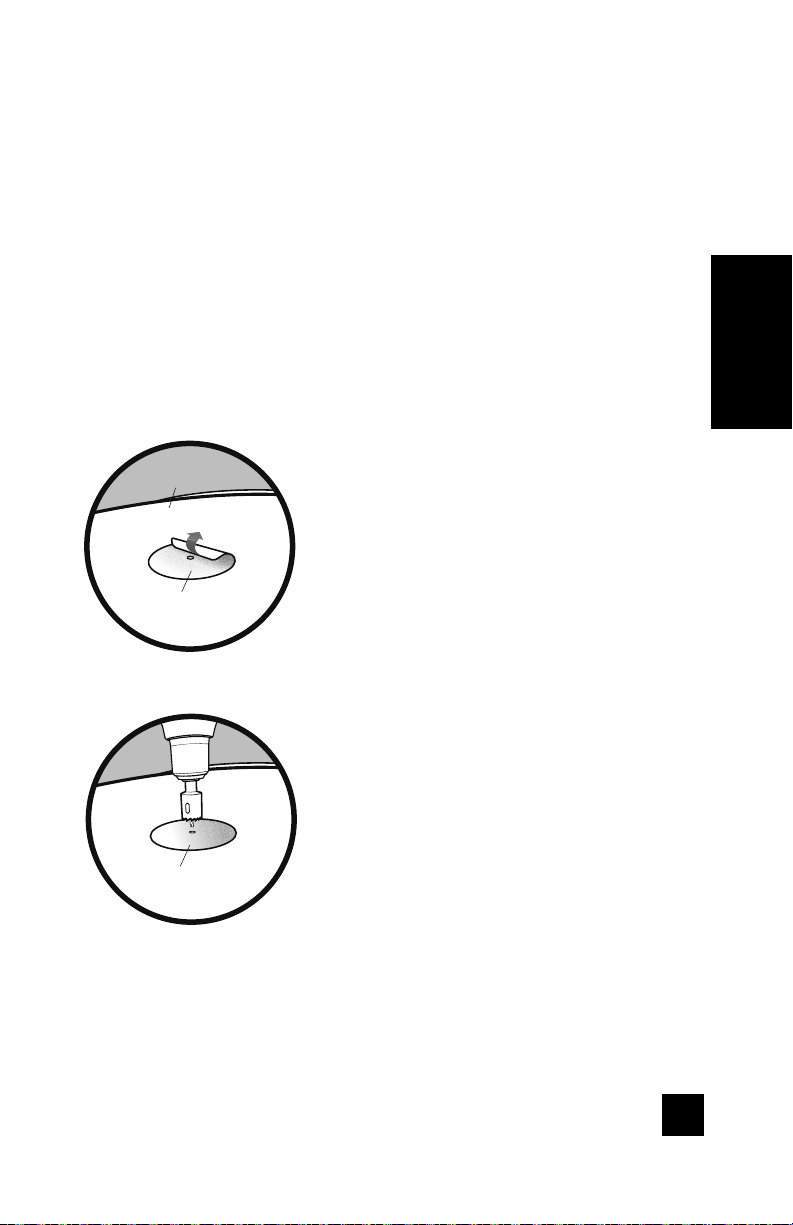
Locate a place where cables are already running through the firewall
(rear wall of engine bay) to the inside of the cabin.
Locate the same firewall hole from inside of the vehicle cabin.
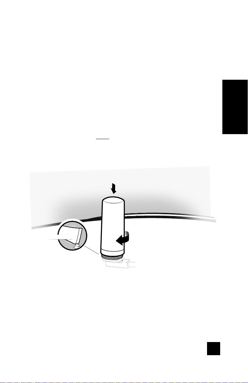
Route the power cables of the power supply from the inside of the
vehicle cabin out through firewall hole.
Note: The cables must be routed inside to outside since the power
supply brick won’t fit through the firewall holes. The power supply
brick should remain inside the vehicle cabin.
Connect the positive lead of the power supply (lead with red tape)
to the disconnected positive (+) lead of the battery (not the positive
terminal on the battery itself).
Connect the negative lead of the power supply (lead without tape)
to the disconnected negative (-) lead of the battery (not the negative
terminal on the battery itself).
Connect the positive (+) lead back to the vehicle battery.
Connect the negative (-) lead back to the vehicle battery.
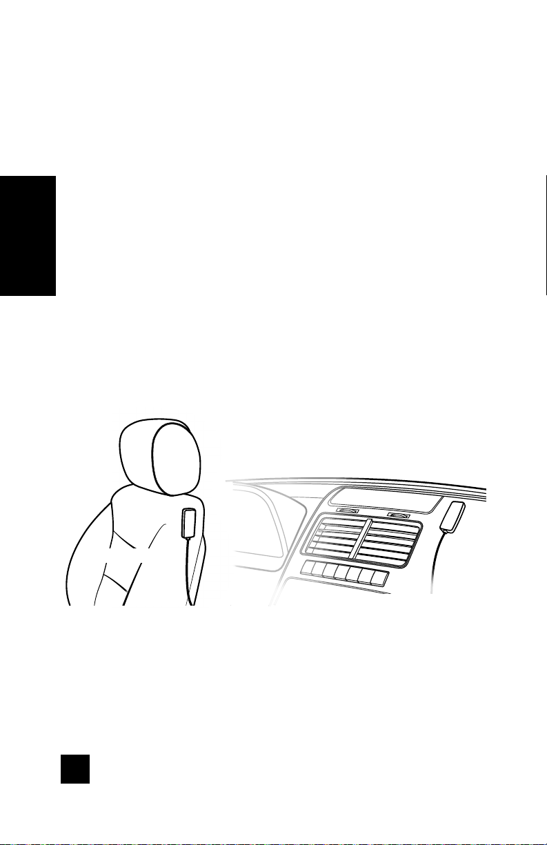
Use steps below as a draft/template of the general install of
the power supply.
______
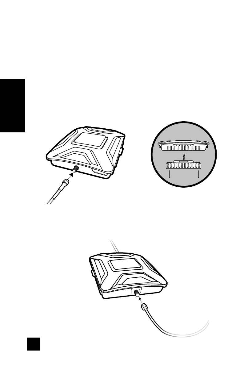
Step 3: Wiring The Power
Supply To Vehicle Battery
1
2
3
4
5
6
7
8
NOTE: Having the power supply directly connected to the battery may
drain the battery’s life. Please review the vehicle’s owner’s manual for more
information. Adding a “fuse tap” may be another solution. A “fuse tap” is an
electrical part that functions as a power splitter and is meant to be installed
in the car’s fuse box, making the amp shut o when the vehicle’s ignition
switch is turned o.

8PROFESSIONAL VEHICLE SIGNAL BOOSTER KIT DRIVE X FLEET
ENGLISH
______
Step 4: Connect Coax Cables
To Booster
Connect the cable from the NMO Outside Antenna to the port
labeled “Outside Antenna” on the Drive X booster.
Connect the cable from the In-Vehicle Antenna to the port
labeled “Inside Antenna” on the booster.
from NMO Outside Antenna
from Inside Antenna
NOTE: Bracket can be used to fasten booster in a specific location if desired.

DRIVE X FLEET PROFESSIONAL VEHICLE SIGNAL BOOSTER KIT 9
ENGLISH
______
Step 5: Connect Power
Supply To Booster
Connect the power supply cord to the end of the Drive X
labeled “Power.” Congratulations! Once your booster is running
please allow some time for your phone to adjust to your
new signal.
NOTE: Do NOT connect the power to the Signal Booster until you have
connected both the Inside and Outside Antennas.
Power Supply

10 PROFESSIONAL VEHICLE SIGNAL BOOSTER KIT DRIVE X FLEET
ENGLISH
______
Light Patterns
Solid Green
This indicates that your booster is functioning properly and there are no issues with
installation.
Blinking Red, Then Solid Green
This indicates that one or more of the booster bands has reduced power due
to a feedback loop condition called oscillation. This is a built in safety feature
to prevent harmful interference with a nearby cell tower. If you are already
experiencing the desired signal boost, then no further adjustments are necessary.
If you are not experiencing the desired boost in coverage then refer to the
Troubleshooting section below.
Solid Red
This is due to a feedback loop condition called oscillation. This is a built in safety
feature that causes a band to shut off to prevent harmful interference with a nearby
cell tower. Refer to Troubleshooting section below.
Light O
If the Drive X Signal Booster’s light is off, verify your power supply has power.
NOTE: The Signal Booster can be reset by disconnecting and reconnecting
the power supply.
After troubleshooting you must initiate a new power cycle by disconnecting and
then reconnecting power to the Booster.
NEED HELP? weboost.ca 866.294.1660

DRIVE X FLEET PROFESSIONAL VEHICLE SIGNAL BOOSTER KIT 11
ENGLISH
FREQUENTLY ASKED QUESTION
Why do I need to create distance between the booster and the antenna?
Antennas connected to a booster create spheres of signal. When these spheres
overlap, a condition called oscillation occurs. Oscillation can be thought of as noise,
which causes the booster to scale down it’s power or shut down to prevent damage.
The best way to keep these spheres of signal from overlapping is to maximize
separation between the inside and outside antennas.
______
Troubleshooting
FIXING BLINKING OR SOLID RED ISSUES
This section is only applicable if the booster is red or blinking red and you are not
experiencing the desired signal boost.
1
2
3
Unplug the Booster’s power supply.
Relocate the inside and outside antenna further from each other. The objective
is to increase the separation distance between them, so that they will not
create this feedback condition discussed before.
Plug power supply back in.
Monitor the indicator light on your booster. If, after a few seconds of ‘power
on’, a solid or blinking red light appears, repeat steps 1 through 3. Increase the
separation distance until the condition is corrected and/or desired coverage
area is achieved. Note: Horizontal separation of the two antennas typically
requires a shorter separation distance than perpendicular separation.
If you are having any diculties while testing or installing your booster, contact
our weBoost Customer Support team for assistance (866.294.1660).
4
5

12 PROFESSIONAL VEHICLE SIGNAL BOOSTER KIT DRIVE X FLEET
ENGLISH
______
Safety Guidelines
This is a CONSUMER device.
BEFORE USE, you MUST meet all requirements set out in CPC-2-1-05.
You MUST operate this device with approved antennas and cables as specified by the manufacturer.
Antennas MUST NOT be installed within 20 cm of any person.
You MUST cease operating this device immediately if requested by the ISED or a licensed wireless
service provider.
WARNING. E911 location information may not be provided or may be inaccurate for calls served by
using this device.
FOR MORE INFORMATION ON REQUIREMENTS SET OUT IN ISED CPC-2-1-05,
SEE BELOW:
http://www.ic.gc.ca/eic/site/smt-gst.nsf/eng/sf08942.html
Use only the power supply provided in this package. Use of a non-weBoost product
may damage your equipment.
All inside antennas must have at least 1.5’ separation distance from all active users.
RF Safety Warning: Any antenna used with this device must be located at least 8
inches from all persons.

DRIVE X FLEET PROFESSIONAL VEHICLE SIGNAL BOOSTER KIT 13
ENGLISH
Drive X
Product Number U460055
Model Number 460055
IC: 4726A-460055
Connectors SMA-Female
Antenna Impedance 50 Ohms
Frequency 699-716 MHz, 729-756 MHz, 777-786 MHz, 824-894 MHz, 1850-1995 MHz, 1710-1755 MHz/2110-2155 MHz
Maximum Power
Power output for single cell
phone (Uplink) dBm
700 MHz
Band 12/17
24.84
700 MHz
Band 13
24.35
800 MHz
Band 5
23.4
1700 MHz
Band 4
21.3
1900 MHz
Band 2
24.43
Power output for single cell
phone (Downlink) dBm
700 MHz
Band 12/17
2.87
700 MHz
Band 13
2.79
800 MHz
Band 5
2.8
2100 MHz
Band 4
2.0
1900 MHz
Band 2
1.92
Noise Figure 5 dB nominal
Isolation > 90 dB
Power Requirements 6 V 2 A
______
Specifications
NEED HELP? weboost.ca 866.294.1660
The term “IC” before the radio certification number only signifies that Industry Canada technical specifications were met.
This device contains licence-exempt transmitter(s)/receiver(s) that comply with Innovation, Science and Economic Development
Canada’s licence-exempt RSS(s). Operation is subject to the following two conditions: (1) This device may not cause interference,
and (2)) This device must accept any interference, including interference that may cause undesired operation of the device.
Changes or modifications not expressly approved by weBoost could void the authority to operate this equipment.

2 YEAR WARRANTY
weBoost Signal Boosters are warranted for two (2) years against defects in
workmanship and/or materials. Warranty cases may be resolved by returning the
product directly to the reseller with a dated proof of purchase.
Signal Boosters may also be returned directly to the manufacturer at the
consumer’s expense, with a dated proof of purchase and a Returned Material
Authorization (RMA) number supplied by weoost. weBoost shall, at its option,
either repair or replace the product.
This warranty does not apply to any Signal Boosters determined by weBoost
to have been subjected to misuse, abuse, neglect, or mishandling that alters or
damages physical or electronic properties.
Replacement products may include refurbished weBoost products that have been
recertified to conform with product specifications.
RMA numbers may be obtained by contacting Customer Support
DISCLAIMER: The information provided by weBoost is believed to be complete
and accurate. However, no responsibility is assumed by weBoost for any business
or personal losses arising from its use, or for any infringements of patents or other
rights of third parties that may result from its use.
3301 East Deseret Drive, St. George, UT
866.294.1660 www.weboost.ca
Copyright © 2017 weBoost. All rights reserved.
weBoost products covered by U.S. patent(s) and pending application(s)
For patents go to: weboost.com/us/patents
NOT AFFILIATED WITH WILSON ANTENNA

FRANÇAIS
DRIVE X FLEET
KIT D’AMPLIFICATION DU SIGNAL CELLULAIRE
POUR VÉHICULE PROFESSIONNEL
UNE MARQUE WILSON ELECTRONICS
Guide de l’Utilisateur
BESOIN D’AIDE? weboost.ca 866.294.1660

______
Table des Matières
Contenu de l’Emballage 1
ÉTAPE 1-A: Percez le Trou d’Entrée du Câble dans votre Véhicule 2
ÉTAPE 1-B: Insérez et Acheminez le Câble 4
ÉTAPE 1-C: Montez l’Antenne NMO Extérieure 5
ÉTAPE 2: Montez l’Antenne Intérieure pour Véhicule 6
ÉTAPE 3: Câblez le Bloc d’Alimentation à la batterie du Véhicule 7
ÉTAPE 4: Connectez les Câbles Coaxiaux à l’Amplificateur 8
ÉTAPE 5: Connectez le Bloc d’Alimentation à l’Amplificateur 9
Configuration des Voyants 10
Résolution des Problèmes 11
Consignes de Sécurité 12
Caractéristiques 13
Garantie 14

DRIVE X FLEET KIT D’AMPLIFICATION DU SIGNAL POUR VÉHICULE PROFESSIONNEL
1
FRANÇAIS
________
Contenu de
l’Emballage
Amplificateur
Drive X et
Support
Antenne NMO
Extérieure + Câble
de Montage avec
Connecteur
Antenne
Intérieure pour
Véhicule
Bloc
d’Alimentation
Câble d’Extension
pour Antenne
Optionnelle
Ruban Protecteur
pour l’Installation
Lubrifiant pour
Bague O

2
KIT D’AMPLIFICATION DU SIGNAL POUR VÉHICULE PROFESSIONNEL DRIVE X FLEET
FRANÇAIS
______
Étape 1-A: Percez le Trou
d’Entrée du Câble dans votre
Véhicule
Identifiez l’emplacement de votre antenne NMO
extérieure sur le toit de votre véhicule qui est:
Près du centre du toit
À au moins 30 cm (12 po) de toute autre antenne
À au moins 15 cm (6 po) de toute fenêtre
(pour optimiser les performances, eectuez
l’installation sur le toit du véhicule)
Testez l’installation avant de percer le trou
d’entrée du câble.
Installez le système en faisant passer le câble
à travers une porte ouverte ou une fenêtre,
terminez les instructions d’installation, vérifiez
que le système fonctionne correctement, avant
de percer le trou.
15 cm (6 po) des fenêtres
(toit ouvrant compris)
Bon emplacement de
l’antenne NMO extérieure
Table of contents
Languages:
Other Wilson Electronics Automobile Accessories manuals
Popular Automobile Accessories manuals by other brands

Camcar
Camcar 40088 Al quick start guide

Lift Tek
Lift Tek AA41 quick guide

Bestop
Bestop TrekStep Side-Mount installation instructions

Directed
Directed Directechs DB3 installation guide

Racelogic
Racelogic DSP05-M quick start guide

Andersen Hitches
Andersen Hitches Ultimate 5th Wheel Connection installation manual