© by WilTec Wildanger Technik GmbH Item 60280 Page 3
http://www.wiltec.de 10 2023-1
Introduction
Thank you for choosing to purchase this quality product. To minimise the risk of injury, we ask you to
always take some basic safety precautions when using this product. Please read this operating manual
carefully and make sure that you understand it.
Keep these operation instructions in a safe place.
Safety instructions
•Place the stand on a level surface.
•The maximum capacity of 30 kg must not be exceeded.
•Keep the main beam vertical to prevent the unit from wobbling.
•Before use, check that the screw connection is tight and correct.
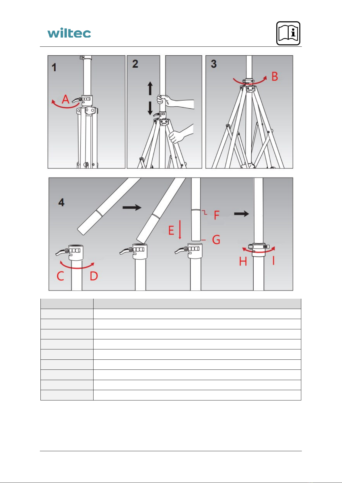
Assembly steps
1. Untighten the quick release of the main body.
2. Fold out the main body 90° towards the ground.
3. After fully opening the bottom of the frame, tighten the quick release by turning it clockwise.
Close the quick release when you feel a resistance.
4. Tighten the quick release on the top of the lower tube outwards and loosen the lower bolts.
Insert the upper telescopic tube into the recess/cap end of the lower tube first. If it is difficult to
insert, make sure that the quick release is fully untightened. When inserting the telescopic tube,
you can start with a slight angle to make it easier to open the clamp.
5. Tighten the screw under the quick release at the top of the lower tube. Turn the quick release
clockwise as far as it will go, then close it to make sure that the telescopic tube is locked.
6. Insert the nuts into the slot on the back of the tool tray on the lower tube. You may need to hold
the tray and nuts with your other hand while tightening the screws. The tool tray can be mounted
on the upper or lower tube accordingly.
7. Spread the quick release at the upper end of the telescopic tube upwards and untighten the
lower screws. Insert the upper cross tube into the plastic connection at the upper end of the
telescopic tube. Once the correct position of the cross tube and correct clamping angle have
been ensured, turn the quick release clockwise as far as it will go, then close it to ensure that
the cross tube is locked.
Attention! Do not extend beyond the recess of the max. length at the end of the cross tube.
8. Adjust the inner diameter and angle of the clamp and the length of the cross tube by tightening
the quick release and wing nut. Tighten the nut firmly and close the quick release before use.
Attention!
•Inner diameter range of clamp: 25–55 mm
•The cross tube can be rotated 360° in horizontal direction.
•The clamp can be rotated 360° in vertical direction.
9. Repeat step 8 to place the bicycle frame in the clamp.
10. and 11. Depending on the style and size of the bicycle, you can adjust the angle and position of
the clamp arm to ensure that the bicycle is balanced.
12. and 13. Adjust the length of the balance pole. Then attach two rubber straps to the handle-
bars/bicycle and to the vertical tubes.