Wilton 8020 User manual

Table of Contents
Cover Page . 1
GeneralSpecifications 4
OperatingPrecautions 5
OperatingInstructions 8
Maintenance 11
ElectricalSchematics 15
Troubleshooting. 16
ReplacementParts.. 17
3

GeneralSpecifications -----------
~.".,
~~
I11-:- 'I)
I,\);
;---1 \\ dI
I
I
.~
~/.. ~
The Wilton Model 8020 and 8120 Vertical Band Saws
are multi-purpose, metal cutting band saws that will
suit almost any metal working application. Typical
applications include contour sawing, beveling, slicing,
ripping, and stack cutting. The saws have a tilting
table and a useful speed and pitch selector. 'LJI~-\~~
Standard Model 8020 is equipped with a two-speed
gearbox. Higher speed Model 8120 is equipped with
a three-speed gearbox.
r--+---..--
~:i[~£i,~~="~~J
' , .---=:--,--- ~-
n~:.. 'I, ---
lono ~= .\:.L~
~' --==~r~
~ n ..~
~,s:;", Jr~
--~ '--~
~@J I
I~l
I~I~lic;..,
~ e:;:J \~. 1
I ~ ;--~ \'t?
~~,,~
.?' ~
]'? ~
<~ ~ ~-..J ~'" ~1
' [..c;)
~~j lvj.
.~;--~~
~
An optional blade welder, mounted on the saw,
provides a means to quickly weld and anneal new or
broken saw blades. The welder includes a blade
shear and weld grinder. (The welder is available in
220VAC or 440VAC power.)
Standard Model 8020 is connected for 220VAC
power unless otherwise specified. All models are
equipped with 3-phase, 220/440V, 115 V at switch
and magnetic starter.
Specifications
4
Vertical Band Saw 8020 8120
Cutting Capacity 10-5/8inches (1 mmto 270 mm) 10-5/8 inches (1 mm to 270 mm)
ThroatDepth 19-5/8inches (500 mm) 19-5/8 inches (500 mm)
TableSize 24-1/4 by 24-1/4 inches 24-1/4 by 24-1/4 inches
BladeWidth 1/8-inchto 3/4-inch (2-19 mm) 1/8-inchto 3/4-inch (2-19 mm)
Lengthof Saw Blade 155to 158inches 155to 158 inches
BeltSteplessVariableSpeed 82 to 1312feet per minute 79 to 5088feet per minute
(25-400 m/min) (25-1550 m/min)
MainMotor 2 hp 3hp
TableTilt
Right 45 degrees 45 degrees
Left 15degrees 15degrees
Front/Back 10degrees 10degrees
HeightofTable 40-3/4inches (1035 mm) 40-3/4inches (1035 mm)
Dimensions
Height 77-1/8 inches (1960mm) 77-1/8 inches (1960 mm)
Depth 47-1/4 inches (1200 mm) 47-1/4 inches (1200 mm)
Width 29-1/8 inches (740 mm) 29-1/8 inches (740 mm)
NetWeight 1102pounds 1102pounds
Optional Welder
Model 8002 8002
ElectricalRating 5kva 5kva
GrindingMotor 1/8 hp 1/8 hp

- Misuse of this machine can cause serious injury.
- For safety, machine must be set up, used and
serviced properly.
- Read, understand and follow instructions in the
Operating Instructions and Parts Manual which was
shipped with your machine.
When Setting up Machine:
- Always avoid using machinein dampor poorly
lightedworkareas.
- Always be sure the machine support is securely
anchored to the floor or the work bench.
When Using Machine:
- Always wear safety glasses withside shields (See
ANSIZ87.1)
- Neverwear loose clothingorjewelry.
- Never overreach - you may slip and fall.
When Servicing Machine:
- Always disconnect the machine from its electrical
supply while servicing.
- Always follow instructions in Operating Instructions
and Parts Manual when changing accessory tools
or parts.
- Never modify the machine without consulting
Wilton Corporation.
You - the Stationary Power Tool User -
Hold the Key to Safety.
Read and follow these simple rules for best results
and full benefits from your machine. Used properly,
Wilton's machinery is among the best in design and
safety. However, any machine used improperly can
be rendered inefficient and unsafe. It is absolutely
mandatory that those who use our products be
properly trained in how to use them correctly. They
should read and understand the Operating Instructions
and Parts Manual as well as all labels affixed to the
machine. Failure in following all of these warnings
can cause serious injuries.
Machinery General Safety Warnings
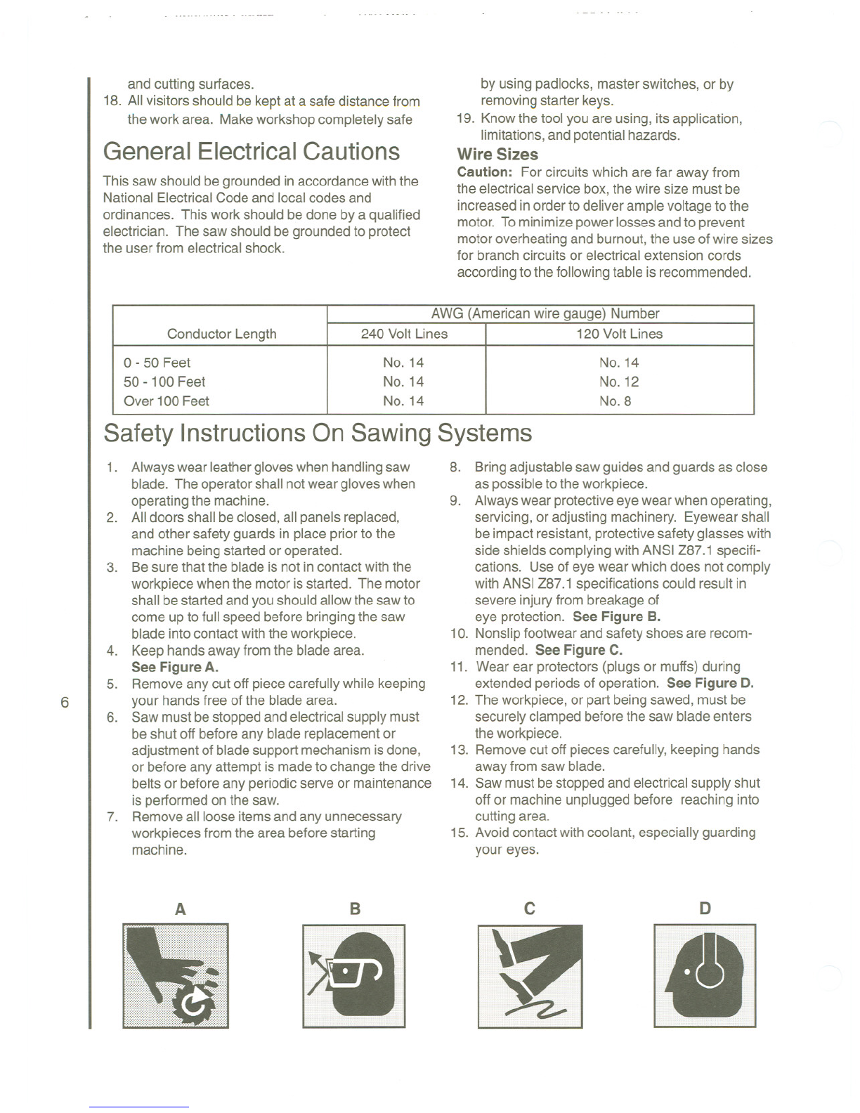
1. Alwayswear protectiveeyewear when operating 8.
machinery. Eye wear shall be impact resistant,
protectivesafety glasseswith sideshieldswhich
comply with ANSI Z87.1 specifications. Useof
eye wear which does not comply with ANSIZ87.1
specifications could result in severe injuryfrom
breakage of eye protection.
2. Wear proper apparel. No loose clothingor
jewelry which can getcaught inmoving parts.
Rubbersoledfootwear isrecommendedfor
bestfooting.
3. Do notoverreach. Failureto maintain proper
working position can cause you to fall intothe
machineor cause your clothingto get caught
pullingyou intothe machine.
4. Keep guards in place and in properworking
order. Do notoperatethe machinewith
guardsremoved.
5. Avoid dangerousworkingenvironments. Donot
use stationary machinetools inwet or damp
locations. Keepwork areas clean andwell lit.
6. Avoid accidental starts by beingsurethe start
switch is OFF before plugging inthe machine.
7. Never leavethe machinerunningwhile unat-
tended. Machineshallbeshutoffwheneverit
is not in operation.
Disconnectelectricalpower beforeservicing.
Whenever changing accessoriesor general
maintenanceis done onthe machine, electrical
powertothe machinemustbedisconnected
beforework is done.
9. Maintainall machinetoolswithcare. Followall
maintenanceinstructionsfor lubricatingandthe
changingof accessories. No attemptshall be
madeto modify or have makeshiftrepairsdone to
the machine. This notonlyvoids the warranty but
also rendersthe machineunsafe.
10. Machinery mustbe anchoredto the floor.
11. Securework. Use clampsor a vise to hold work,
when practical. It is safer than using your hands
and itfrees both handsto operate the machine.
12. Neverbrush away chipswhile the machine is in
operation.
13. Keepwork area clean. Cluttered areas invite
accidents.
14. Removeadjustingkeysandwrenchesbefore
turning machineon.
15. Usethe righttool. Don't force a tool or attach-
mentto do a job itwas not designedfor.
16. Useonly recommendedaccessoriesand follow
manufacturersinstructionspertainingtothem.
17. Keep hands in sight and clear of all moving parts
5

and cutting surfaces.
18. All visitors should be kept at a safe distance from
the work area. Make workshop completely safe
General Electrical Cautions
This sawshould begroundedinaccordancewiththe
National ElectricalCodeand localcodes and
ordinances. This work should bedone by a qualified
electrician. The saw should be groundedto protect
the user from electrical shock.
by using padlocks, master switches, or by
removing starter keys.
19. Know the tool you are using, its application,
limitations, and potential hazards.
Wire Sizes
Caution: For circuits which are far away from
the electricalservice box,the wire size mustbe
increasedinorderto deliverample voltageto the
motor. Tominimize powerlosses andto prevent
motoroverheatingand burnout,the use ofwire sizes
for branch circuits or electrical extension cords
accordingto the followingtable is recommended.
Safety InstructionsOnSawing Systems
6
1. Alwayswearleathergloveswhenhandlingsaw
blade. The operatorshallnotweargloveswhen
operatingthe machine.
2. Alldoors shall beclosed,all panelsreplaced,
and other safety guards in place priorto the
machine beingstartedor operated.
3. Besurethat the blade is not incontactwith the
workpiecewhenthe motorisstarted. The motor
shall bestarted andyou shouldallowthe sawto
come up to full speed beforebringing the saw
blade intocontactwiththeworkpiece.
4. Keephandsawayfrom the blade area.
See Figure A.
5. Remove any cut off piececarefully while keeping
your handsfree of the blade area.
6. Saw mustbestopped and electricalsupplymust
be shut off before any blade replacementor
adjustmentof bladesupportmechanismisdone,
or before any attempt ismade to changethe drive
belts or beforeany periodicserve or maintenance
is performedonthe saw.
7. Removeall loose itemsand any unnecessary
workpieces from the area beforestarting
machine.
AB
>8
8. Bringadjustablesaw guidesand guardsas close
as possibleto the workpiece.
9. Alwayswearprotectiveeyewearwhen operating,
servicing,or adjusting machinery. Eyewearshall
beimpact resistant,protectivesafety glasseswith
side shields complyingwith ANSI Z87.1 specifi-
cations. Use of eye wear which does not comply
with ANSI Z87.1 specificationscould resultin
severe injuryfrom breakageof
eye protection. See Figure B.
10. Nonslipfootwear and safety shoes are recom-
mended. See Figure C.
11. Wear ear protectors (plugs or muffs) during
extended periods of operation. See Figure D.
12. The workpiece, or partbeing sawed, must be
securelyclamped beforethesaw blade enters
theworkpiece.
13. Removecut off piecescarefully,keeping hands
awayfromsaw blade.
14. Sawmustbestoppedand electricalsupply shut
off or machine unplugged before reaching into
cutting area.
15. Avoidcontactwithcoolant,especiallyguarding
your eyes.
c D
.
AWG (Americanwire gauge) Number
Conductor Length 240 Volt Lines 120Volt Lines
0 - 50 Feet No. 14 No.14
50 -100 Feet No. 14 No.12
Over 100Feet No. 14 NO.8

Introduction
This manual includes the operating and maintenance instructions for the Wilton 20-inch Vertical Band Saws,
Models 8020 and 8120. This manual also includes parts listings and illustrations of replaceable parts. Typical
operations performed using the band saw are shown below.
RIPPING
SLOTTING
SPLITTING
STACK CUTTING
THREE-DIM.CUTTING
SLICING
SEGMENTING
ANGULAR CUT
EXTERNAL CONTOUR
SHAPING
BEVELING
SHAPING CUT
GRINDING RELIEF
7
INTERNAL CONTOUR
COMPOUNDANGLECUT

Saw Features
Referto Figure1forkeyfeaturesofthe
14-lnchVari-SpeedVerticalBandSaw.
Speed I,-,-; 1
'
i'-.
and Pitch iv'L1CJ~jl
Selector 'I',IGUideSu
Upper 0
,
.'~~':C'
I.~
I
.
H
'
andWh~~?rt
Wheel @J cI
Door' I Work Lamp
Location I
I
1
:e;)l
,
.,,
(r~ .
~7
for
:
\,-n s~
Optional' Ii /J
Welder 0If- .-. I H,~'
RM'"
In_~lT~- ,
1'
.
~'
,
,
Fl,exible
ear
I
I~-lJ .IS='" i\~ DO_'" Air Line
Blade 0 . .IC-., Blade'
Guard '.' I
I
\~I suppo~tUlde
ON/OFF [0, L- \~~J
SwitCh~j .I I Blade
YJJ ~J.I /L./ Tensi
o.
1
-~. ,, Hnlng
E-Stop V-~Cf--~' ~d
I- ,
T1l
1
-
.
--
.
'
.
/~-:-
...
~"'=-
.
-"/"/-//// -. Wheel
,i(\~~l'Jl:-=:-~/s~:jJ>c-- I///===:J
~.\, ); <. it T]l -n-""// ~J
",e-'.,'''>; ,1"1' ~r:'; - "---
Variable t~.
\~.
"
.
;I
.
-<l
l
/J
I
-UJ>t-~
.
/
.
-=-
.
--=--"
1
1 ~~~~
Speed
I
c::;~ "'- -:://J
Control ('c-.J
.
@rl [
,
.
.,
JC!?
.
1
0c
1
-C:.IJ
c ; C<::::
1
[<--J //J
0:') G~~?
Lower I- .~, c >i \(;::.:~
1
Wheel I C~ \f~ 1
Doord ~-- C../J ~'-j)
--~ --- ~- c::~ ~Gearbox
---~ :--~ tJ
-~ ~ Ishift lever
~~-
I
2;:? (/ I
Chi
pTr ~~ (/:.\-/<s>
(. ay ~f
Inside door~.:!/>
8Figure 1: Saw Features (Left Side
View)
Guide Support
Clamping Knob
Guide Support
Hand Wheel
Blade Tensioning Hand Wheel
Figure 2: Saw Features (Right Side View)
Setup
Installation
Theframe ofthe vertical bandsaw hasfour mounting
holes inthe base of the sawframe. The band saw may
be secured to thefloor using thefour mounting holes.
Electrical Connection
Referto the Wiring Diagramsection for wiring informa-
tion. Connectionto facility electrical power should be
made by a qualified electrician.
Operating Instructions
Operating Controls
The operating controls (refer to Figure 3) for the saw are
located on the left side of the machine. The controls
include the following:
ON/OFF
Switches
Turn Counter-
Clockwise To
Decrease Speed -Tum
Clockwise
To Increase
Speed
Variable
Speed Crank
(turn only when
saw is operating)
Figure 3: Operating Controls
1. A set of start/stop push buttons, located below the
optional welder, provide a means to start and stop
the saw drive motor.
2. A variable speed control (crank), which can only
be adjusted while the saw is running, is located
below the start/stop buttons.
3. A blade tensioning hand wheel is mounted on the
top of the saw enclosure.

4. Referto Optional Welder for a description of the
weldercontrols.
The Model8020 band saw is equippedwitha two-
speed gearbox. The shift leveris locatedonthefront
of the band saw. Shift positions are L (low)and H
(high).
The Model8120 band saw is equippedwith a three-
speed gearbox. The shift leveris locatedonthe front
of the band saw. The shift positions are L (low),M
(medium),and H (high).
Optional BladeWelder
An optional blade welder is available on the vertical
band saw. The welder has all the features required to
cut, weld, and anneal the saw blade.
Welder Features
(refer to Figure 4)
The welder is installed on the left side of the saw
enclosure. A blade cutter, provided with the welder, is
mounted on the saw enclosure near the welder panel.
0 0
'"''''''
"Tro,
Welding
Button
Annealing
Button
Clamp
Pressure
Selector
LOWE/::
~H'GHER
[
VOLT'-Y
2~ 4 MOTOR'-HP_~
\\'::Jf~ ~fLDELy_~w.1
I 0 5 5~~~'
IClA'.\P P"""LRE I
Clamp (2)
001, Clamp
Handle (2)
Light
Switc ON ON Grinder
Switch
OFF
LIGHT
Blade
Grinder
00
Figure 4: Welder Features
The welder has two clamps that hold the ends of the
saw blade during welding. The welder controls
include a clamp pressure selector, welding, and
annealing pushbutton switches, and switches for the
blade grinder and welder light.
Operating the Welder
(refer to Figure 5)
WARNING: BE SURE TO WEAR EYE PROTEC-
TION WHILE OPERATINGTHE WELDER TO
AVOID EYE INJURIES. USE CARE WHEN HAN-
DLINGTHE BLADEAFTERWELDING TO AVOID
BURNS.
1. Usingthe bladecutter,cut the bladeto the
required length (ViewA).
2. Usingthe bladegrinder,square-offthe blade
ends (View B). The bladeends needto be
perpendicularto the side ofthe blade. The
bladeends mustbesquaresothere is minimal
gapbetweenthe endswhenclampedforweld-
ing.
3. Insertone endof the bladeinthe leftclamp
(ViewC). Positionthe back edge of the blade
againstthe back of the leftclamp. Then position
the endofthe blade midwaybetweenthe left and
rightclamps. Tightenthe leftclamp.
4. Insertthe other end ofthe blade inthe right
clamp. Positionthe back edgeof the blade
againstthe back of the rightclamp. Then butt
the end ofthe bladeagainstthe other end of
blade (the bladeends needto be incontact with
each other). Tightenthe rightclamp.
5. Setthe clamp pressureselector switch (clock-
wise rotation)to thesetting requiredfor the width
ofthe blade beingwelded(seethetable below). 9
NOTE: There will be some resistance when turning
the switch.
6. Pressand holdthe weld pushbutton. When the
pushbuttonis pushed,the rightclamp movesto
the leftto apply pressureto the blade ends. At
the sametime, sparkswill comefromthe blade
ends asthey are beingwelded.
BladeWidth ClampPressure
(Inch) SelectorSetting
1/8"to 1/4" 1
5/16" to 3/8" 2
1/2" 3
5/8" 4
3/4" 5

({p
Figure 5: Operating the Welder
7. Release the weld push button and unclamp the left
and right clamps.
8. Rotate the clamp pressure switch (clockwise) to
the zero position.
9. Center the weld between the two clamps. Tighten
the clamps.
10. The weld is hard and brittle and must be annealed
before use. To anneal the weld, quickly depress
and release Gog)the anneal pushbutton. Repeat
the depress-and-release process until you see a
red glow (slightly red) from the weld area.
CAUTION: DONOT PRESSAND HOLDTHE
ANNEAL PUSHBUTTON. THEWELD WILLBE
OVERHEATEDANDTHE WELD WILL FAILDUE
TOTHEEXCESSIVEHEAT.
10
11. Release both blade clamps and remove the
blade.
12. Check the integrity of the weld. Bend the blade to
form a radius in the blade at the point of the weld.
The size of the radius should be approximately
the same as the radius of the saw drive wheel.
The weld must hold and not break or crack after
forming the radius. If the weld breaks, cut away
the welded area and repeat the welding/annealing
process.
CAUTION: CHECKTHE BLADETO MAKE
SURETHEWELDEDSECTIONISTHE SAME
THICKNESSAS THE RESTOF THE BLADE. IF
THE BLADE ISTHICKERATTHE WELD,THE
BLADEGUIDESMAYBEDAMAGED.
13. Check to make sure the welded section is the
same thickness as the rest of the blade. If not,
grind off excess weld material using the grinder
on the welder.
Setting Blade Speed
WARNING: NEVER OPERATE THE SAW WITHOUT
BLADE COVERS IN PLACE AND SECURED.
CAUTION: DONOTTURNSPEEDSETTING
CRANK UNLESSTHE SAWMOTOR ISOPERAT-
ING. THE SPEEDSETTINGMECHANISMCAN BE
DAMAGED.
1. Referto the Speedand Pitchselectoron the left
side ofthe saw enclosure. Select the speed
settingfor the materialto be cut.
2. Shiftthegearboxto the requiredspeed setting
(Model8020: highor low) (Model8120: high,
medium,or low).
3. Start the saw usingthe start pushbutton.
4. Turnthe speed setting crankto the required
speed. Turningthe crankto the right (clockwise)
increasesspeed. Turning the crank to the left
(counterclockwise)decreasesspeed.
Blade Selection
The vertical band saw is equipped with a Wilton part
number 910839 saw blade that is adequate for a
variety of common materials. The blade is a 10-tooth,
1/2-inch multi-purpose.
(Refer to the speed and pitch indicator on the left side
of the vertical saw to select the blade and speed
required for various materials.)

A coarse blade is generally usedfor a solid steel bar
but a finer tooth blade used on a thin-wall tube. In
general, the bladechoice is determined bythe
thickness ofthe material;thethinnerthe material,the
finer the tooth pitch.
Forvery high productionon cutting of special
materials, or to cut hard-to-cut materialssuch as
stainless steel,tool steel, ortitanium, contactyour
industrial distributor for more specific blade recom-
mendations. Also,the supplierwho providesthe work
piece material should be preparedto provide you with
very specific instructions regardingthe best blade for
the materialandshape supplied.
Setting Blade Guide Support
(refer to Figure 6)
Blade
Guide
Rod
~,;~ .
-\.
"r~\1
"" ~,
\~~~I
~
~
Ili~
:'rI<1 I 't. .\\
.}Adiust Up \\
or Down
\
11\ II. I I
I
as Required.
il\~ j)
'I
II
Blade
Guide
Rod
Hand Wheel II
II J
Blade
Guides
~
Figure 6: Setting Blade Guide Support
The blade guide support must be adjusted for the
thickness of the material to be cut. Adjust the
position of the support as follows:
1. Loosenthe bladeguidesupportbyturningthe
handwheel onthe leftsideofthe sawenclosure.
2. Placethe material to be cut adjacent to the blade
guide. Adjust the blade guide supportupor down
usingthe handwheelonthe front ofthe enclo-
sure. Adjust untilthere is clearance betweenthe
materialto be cut andthe blade guide.
3. Tightenthehandwheel.
Maintenance
Cleaning
WARNING: DISCONNECTELECTRICAL POWER
TOAVOIDPOTENTIALFORUNINTENDEDSTART-
UPDURINGMAINTENANCE.
1. Periodicallyemptythe chip pan(insidethe lower
dooronthe leftside ofthe machine).
2. Usea brush to loosenaccumulatedchips and
debris. Use vacuum cleaning to remove accu-
mulateddebris.
Lubrication
Bearings: The bearingsusedinvertical bandsaw
arepre-lubricated,sealedbearingsand requireno
additionallubrication.
Air Pump: Lubricatethe air pumpeverysix
months. Addoil throughthe oil fitting on the
frontofthe bandsaw.
Changing Saw Blades
(Refer to Figure 7)
II
Table
Insert Blade
Guards
Idler
Wheel rn II
Blade
Tension
I-ia"rlAteeI 111
~ II
Figure 7: Changing Saw Blades

II II II
LowerVari-Speed
¥~;" v
Adjustment Slots" ~ ~
, 'e" u ,
II' UpperVari-
IG.."'''Dri''BoIts ! I r~,~~~~~:~;y
y,~ Slots
0, ~ ~~
GearboxDrivePulley I~II II ~AIII, - '\\ JJ---,! I
Jressor ~,
,"/ ((QJ ff:'
II I\( 0: J!i/t I\\'~\ ##/
'" ,en 1\1 \ )\~ C(~ 'j yP/;T~c~ ,
\\\""
'
1/// LowerVari-speed
~~ ,~~, 0I\ I~ '~'-Y t;/ {~~ "'~ DnvePulley
'" "'\7v"7\. y .~
~~~
,
~/i~'
\~, ~7~~,~
~,/, ~/ ,\, ~
,
' ';f I,
111 111
,1/I vari-speed
~~~\j i/I~ ,
!II ,\\\.\/ /Ii
,
/\~DriveBelt
~~jZ .,,' ,~'" '"qyi "~
'
:\~r~ ~'::'>",,\ '.
~~~e
'~~\~ 'p~----
Ii( ~ ~ I ~ / ----
~ (
,Ii
""" iQ'~OIJ
,/~~---~ ~DriveMotor
~, \,', /~Pulley
\. ~ / DriveMotor Drive
~ompressor Hold-down Bolts Motor
Drive Belt
Figure 8: Changing Drive Belts
WARNING: DISCONNECT ELECTRICAL POWER
TO AVOIDPOTENTIAL FOR UNINTENDED
START-UPDURINGMAINTENANCE.
12
Followthe proceduresbelowto changethe saw
blade:
1. Open upperand lowerdoors onthe left sideof
the bandsaw.
2. Removethefront and rearbladeguards.
WARNING: ALWAYSWEAR LEATHERGLOVES
WHEN HANDLING SAW BLADETO AVOID
INJURY FROMTHE SAWTEETH.
2. Removethewornbladeand installthe newblade.
Installthe bladesotheteethfacingdownward
wherethe bladepassesthroughtheworktable.
3. Usingthe hand wheelon the undersideof the
upperenclosure,tightenthe blade.
4. Installthe front and rearbladeguards.
5. Closethe accessdoorsandstart the saw.
6. Observethe tracking of the blade. Referto
Adjusting BladeTracking ifthe bladedoesnot
track properly.
Changing Gearbox Drive
Belts
(refer to Figure8)
WARNING: DISCONNECTELECTRICAL POWER
TOAVOIDPOTENTIALFOR UNINTENDED
START-UPDURINGMAINTENANCE.
Followthe proceduresbelowto changethe saw
blade:
1. Removecover on rightside ofthe bandsaw.
2. Loosenboltsonthe uppervari-drive support.
3. Removewornbeltsandinstallnewbelts.
4. Slide uppervari-drive pulleysupportto apply
tensionon belts. Tighten boltson uppervari-drive
pulleysupport.
5. Installcover on right side of the bandsaw.
6. Checkoperation of the band saw.
Changing the Drive Motor/Air
Compressor Belts
(refer to Figure 8)
WARNING: DISCONNECT ELECTRICAL POWER
TO AVOID POTENTIAL FOR UNINTENDED START-
UP DURING MAINTENANCE.

Follow the procedures below to change the drive
motor and/or air compressor belts:
1. Removecover on rightside ofthe bandsaw.
2. Loosenboltsonthe uppervari-drive pulley
support. Slide uppervari-drive pulleysupportto
releasetension on belts. Donot removethe saw
wheeldrivebelts.
3. Loosenboltsonthe lowervari-drivepulley
support. Slide uppervari-drive pulley
support to releasetension on belts. Do not
removethegearboxdrivebelts.
4. Removewornbelts. Installnewbelts.
NOTE: It may be necessary to loosenthe drive
motorattachingscrews to haveenoughslackto
removethe aircompressordrivebelt.
5. Slide uppervari-drive pulleysupportto apply
tension on belts. Tighten boltson uppervari-
drive pulleysupport.
6. Installcover on right side of the bandsaw.
7. Check operation of the band saw.
Changing the Vari-Speed
Drive Belts
(refer to Figure 8)
WARNING: DISCONNECTELECTRICALPOWER
TOAVOIDPOTENTIALFORUNINTENDEDSTART-
UPDURINGMAINTENANCE.
Follow the procedures below to change vari-speed
drive belts:
1. Removegearboxanddrivemotorbelts(referto
Changing Gearbox Drive Belts and Changing
the Drive Motor/Air Compressor Belts).
2. Removelowerdrivepulley(ref.#45)fromlower
shaft(ref.#40).
3. Removeupperdrivepulley(ref.#46)fromupper
shaft(ref.#27)to removeand lowervari-speed
mechanisms.
4. Removewornvari-speeddrivebelt.
5. Installthevari-speedmechanismandupperand
lowerdrivewheelsupports(ref.#38 and#23).
6. Installupperdrivepulley(ref.#46)andlowerdrive
pulley(ref.#45).
7. Install drive motor and gearbox belts (refer to
Changing Gearbox Drive Belts and Changing
the Drive Motor/Air Compressor Belts).
8. Checkoperationofthe bandsaw.
Replacement of Blade
Guides
(refer to Figure 9)
Figure 9: Replacement of Blade Guides
When removingupperbladeguides, removeblade
guardfromguidesupport.
1. Whenremovingthelowerbladeguides,open
lower leftdoorto access bladesupport (the lower
bladeguardis attachedto the lowerdoor).
2. Removethe cap screwandwashersfrom both
bladeguides.
3. Removethe bladeguides.
4. Installnewblade guidessothey just touchthe
side ofthe saw blade. Adjust position of guide
seat so itjust touches the back edge ofthe blade.
13
Replacement of Chip Brush
(refer to Figure 10)
WARNING: DISCONNECTELECTRICALPOWER
TOAVOIDPOTENTIALFORUNINTENDEDSTART-
UPDURINGMAINTENANCE.
Follow these procedures to change vari-speed drive
belts:

1. Open dooron lowerleft ofthe band saw.
2. Removeattachingscrewandwasher.
3. Removebrush.
4. Installreplacementbrushand securewithscrew
andwasher.
<I
I,
I/,/
~~~
.1f
.~;;fr,~ .
Drive
\Iii (IIf II!
~~" :1~~~ I\~/'<~\I
"I(~~'2I~~?" I
lil",\,
."'1\ ~1@0~ '
>~~~~~~ )
.11
\\\\j/' // \ \~ "~j!i
\\\~;:/-\\ \1 ~. ///,
I'I\
'I\"
~
\\: I
I
\1)$
\
\1, I, 4
'I I, ~\<lII';\\j!
"
\
\~~----------
,/
[--------.---------------I
Figure 10: Replacement of Chip
Brush
Adjustments
Blade Tracking
14 Blade tracking can be corrected using the following
procedure:
1. Operatethe sawto determineifthe bladeis
tracking off center. Determine ifthe blade is
tracking to the rightor to the left.
2. Toadjusttracking,turnthe tracking adjustment
knob on the right side ofthe machine (refer to
Figure 2for location of blade tracking adjust-
ment knob).
3. Ifthe bladetracksto the right,the bottomofthe
bladedrivepulleyneedsto be movedoutward.
4. Ifthe blade tracks to the left,the bottomof the
bladedrive pulleyneedsto bemovedinward.
Work Table
The positionofthe work tablecan be adjustedto tilt
either left or right (approximately10 degrees ineither
direction).
The work table can also be adjusted to tilt approxi-
mately 45 degrees to the rear and 45 degrees to the
front.
Front/Back
(referto Figure11)
I
1- 1. Loosenhexnut.
2. Tilttabletothe desired position.
3. Tightenhexnut.
Table
~-/
~7----
\'0~\\\.~ -/------
..j -~ 0I" Table
~~!'Pi!\!f:! ,~s""
rI~r \I,
I\
~Angle
''I \\ Scale
1 ~~ ~~)L-J
!~~
.
~Ir- 'I /
\
"'
P
~L---~) -- / \
'" rJi', A
Oj \\'I "
~~~/ oI, i'
,,° I'TI", 'i I, ' ~
\..-!'-~".../I 1
Clamping Nut
Figure 11:Table Adjustment (Front!
Back)
1. Loosentwo screws.
2. Usingthe adjustmentscrew,tiltthetable tothe
desiredposition.
3. Tightentwoscrews.
.. ~-..
~3~~-S;::>- "
::: / ,_,:::F>-. 'S::
.
:.-~ 'II,-/,/_: .
--.
. '-, /, ,.1 ..//./1'
I.1/1 jrl ~- J
'~--~~":::::cc- :;
\
.
~ ,= - - I '-. '
., I.!/ Iii ",-- /."i ii'> ,
"!:/~1~~1..,/1 !l:~"
I
I
,
.
1I
I
.
-:{ /
;?(Clamping
1'Screw
I
I
'I~\
=:. t- I J, - - -r,;,iD>l
IrFi:I~UII :(L~~~\
Angle Scale
Adjustment Screw
Figure 12: Table Adjustment (Right!
Left)

ANNEALING PUSH BUTTON WELDING PUSH BUTTON
SWIT~ ~ITCH LIGHT
T
~TRANSFORMER
lhm
~
MOVABLE WELDING PAD
SWITCH
- - ---,
3'U
0-0 10--0 IV M
I -L I
T1-0-0 0--0 I W
I I
°- - - - - - - 1
LIGHT
~
~
-
::J
CC
0
-.
Q)
CC
~
Q)
3
I
~
CD
-
a.
CD
~
.....
CJ1
SWITCH
AC
110V
SWITCH
OFF ON
R
R S T
SOURCE
-Z
::r CD
en CD
I» a.
(') 0
(') 0
CD "'"
en "'"
en CD
0(')
"'" -
'<
-
"'"
0::!.
3j
cc
C
;:; ar
0cc
j"'"
I»
3
-
0
"'"

Troubleshooting
16
Fault Probable Cause Suggested Remedy
Excessivebladebreakage 1. Incorrectspeed or feed. 1. Check Machinist'sHandbookfor
"speed/feedappropriatefor the
materialto becut.
2. Teethtoo coarsefor 2. Check Machinist's handbookfor
material. recommendedbladetype.
3. Incorrectbladetension. 3. Adjustbladetensionto the point
wherethe bladejust does notslip
onthewheel.
Prematurebladedulling 1. Bladeteethtoo coarse. 1. Use a finer tooth blade.
2. Bladespeedtoo high. 2. Try a lower blade speed.
3. Insufficientbladetension. 3. Increasetension to proper level.
Bad cuts (crooked) 1. Feedpressuretoo fast. 1. Decreasepressure.
2. Guidebearingsnot 2. Adjust guide bearing clearanceto
adjustedproperly. 0.001 inch (0.002inch maximum).
3. Inadequatebladetension. 3. Graduallyincreasebladetension.
4. Spanbetweenthetwo 4. Move bladeguide barcloser to
bladeguidestoowide. work.
5. Dullblade. 5. Replaceblade.
6. Incorrectbladespeed. 6. Checkbladespeed
(see Figure 3).
7. Bladeguideassembly 7. Tightenbladeguideassembly.
loose.
8. Bladeguidebearing 8. Tightenbladeguidebearing
assemblyloose. assembly
9. Guide bearingworn. 9. Replaceworn bearing.
Unusualwearon side/backof 1. Bladeguidesworn. 1. Replacebladeguides.
blade 2. Bladeguidebearingsnot 2. Adjustbladeguide bearings.
adjusted.
Teethmissing/rippedfrom blade 1. Bladetooth pitchtoo 1. Use bladewith finer tooth pitch.
coarse for work piece.
2. Gulletsloadingupwith 2a. Use bladewith a coarsetooth
chips. pitch-reduce feed pressure.
2b. Brushblade to removechips.
Excessivespeed reducer 1. V-belt istootight. 1. ResetV-belttension.
noise/vibration

Replacement Parts
This section provides exploded view illustrations that show the replacement parts for the Models 8020 and 8120
Vertical Band Saw. Also provided are parts listings that provide part number and description. The item num-
bers shown on the illustration relate the item number in the facing parts listing.
Order replacement partsfrom:
Wilton Corporation
300 South Hicks Road
Palatine, IL 60067
TEL: 1-888-594-5866
FAX: 1-800-626-9676
Identifythe replacementpart bythe part numbershown inthe parts listing. Besureto includethe model
number andserial number ofyour machinewhen ordering replacementpartsto assurethat you will receivethe
correct part.
17

Exploded View - Enclosure
0(er,
47
40
41
~l 4
4:J
51
.. ,.,--- €
Iro,r 1
.s
10
18
A8 -46

Parts List - Enclosure
19
Ref. Part
No. Number Description Qty.
1Box, Electrical 1
5683741 220V
5516262 440 V
2 5680091 Work Lamp 1
3 5516269 Screw, Cap 2
4 5680081 Block, Mtg., Lamp 1
5 5515283 LED Readout,SFPM 1
6 5516271 Bolt, Hex 10
7 5516272 Washer, Flat 10
9.5680101 Cover,Rear 1
10 5516273 Label,GearboxSpeed 1
11 5680031 Bracket, Door 2
12 5516274 Washer, Flat 6
13 5516275 Bolt, Hex 6
14 5680111 Guard,Blade 1
15 5516276 Washer, Flat 3
16 5516277 Bolt, Hex 3
17 5516278 Bolt, Stop 1
18 5516279 Nut,Jam 1
19 5516280 Washer Flat 1
20 5516281 Bolt, Hex 1
21 5516282 Washer, Flat 1
22 5516283 Support,Threaded 1
23 5516284 Support,Stop 1
27 5516285 Screw,Cap 2
28 5516286 Washer, Flat 4
30 5516287 Screw, Cap 2
31 5681411 Plate,Mtg. 1
34 5516288 Screw, Cap 1
35 5516289 Guide/Rest 1
36 5516290 Screw,Cap 2
37 5681401 Blade,Lower 1
39 5516291 Nut,Hex 2
40 5516292 Box, Switch 1
41 5516293 Switch, ON/OFF 1
42 5516294 Switch, E-Stop 1
43 5516295 Label,VariableSpeed 1
44 5516296 Enclosure,Bandsaw 1
45 5680051 Pan, Chip 1
46 5516297 Pin,Hinge 4
47 5683751 Door,Upper 1
48 5683771 Door,Lower 1
49 5516298 Knob, Door 2
50 5681392 Assy., Cutter Edge 1
51 5518151 Switch, Jog 1

Exploded View -Saw Table
'~~ rn-,
,;~r! ~~
1:)9.
/
II
I~-
".~
~:
Ij\i;I i
::~ ;.r
"-K
20
,~ 2a
I
~"'~
f~
, 10
<~
-16
17
116
I
..
JJ
J'8 J1

Parts List - Saw Table
21
Ref. Part
No. Number Description Qty.
15681221 Support,UpperGuide 1
25681271 Guard,BladeUpper 1
3 5516300 Screw,Cap 2
45516301 Screw,Cap 1
5 5516310 Washer, Flat 1
6 5681311 Rod,LowerGuide 1
7 5681291 Support,BladeGuide 1
85681121 Guide,Tungsten 2
95516311 Washer, Flat 4
10 5516302 Screw,Cap 4
11 5681051 Table 1
12 5681061 Plate,Table 1
13 5681071 Washer, Flat 2
14 5516315 Washer, Lock 2
15 5681081 Screw,Plate 2
16 5516309 Screw,Drive 8
17 5681191 Pointer 2
18 5681091 Seat,Table 1
19 5681171 Screw,TiltAdj. 1
20 5681101 Seat,Tilting (UR) 1
21 5516303 Screw,Cap 4
22 5681181 Dial Indicator(UR) 1
24 5516304 Screw,Cap 2
25 5516312 Washer, Flat 2
28 5681131 Screw,Adjustment 1
29 5516305 Screw,Cap 2
30 5681111 Bracket,Adj. Screw 1
31 5516313 Washer, Flat 1
32 5516299 Nut,Jam 1
33 5681201 Seat,Tilting (FIR) 1
35 5516314 Washer, Flat 4
36 5516306 Screw,Cap 4
37 5681141 Support,LowerGuide 1
38 5516307 Screw,Cap 1
39 5516308 Screw,Cap 2
40 5681161 Support,BladeGuide 1
41 5681211 Dial Indicator (FIR) 1
42 5681811 Gauge,Miter 1

Exploded View-Blade Tensioning Mechanism
55'
~
t=-~
36JS~
1I-.
J.',1\ I
~a39I I\1
II I
64 ~--t6
Z9 --,.- n
3~ ~e
$& ',f'--,-
"-~- '-
. ,'.;-,..
~--1 l -
I
22 "hi~
69 "
~~ 82
65
This manual suits for next models
1
Table of contents
Other Wilton Saw manuals

Wilton
Wilton 7060 Instructions for use

Wilton
Wilton 99174 Use and care manual

Wilton
Wilton Miter Band Saw User manual

Wilton
Wilton 8201 Instructions for use

Wilton
Wilton 99192 Use and care manual

Wilton
Wilton 7020/7040 Instructions for use

Wilton
Wilton 8014FW Service manual

Wilton
Wilton 7015 User manual

Wilton
Wilton 3400 Instructions for use

Wilton
Wilton -SX User manual