manuals.online logo
Brands
  1. Home
  2. •
  3. Brands
  4. •
  5. Wimberley
  6. •
  7. Camera Accessories
  8. •
  9. Wimberley F-9 User manual

Wimberley F-9 User manual

The F-9 Wimberley Head Version II Flash Bracket™ is one
of several flash bracket combinations that can be assembled
with the components of the Wimberley Modular Flash Bracket
System. The Wimberley Modular Flash Bracket System brings
a new level of versatility and portability to the world of flash
brackets.
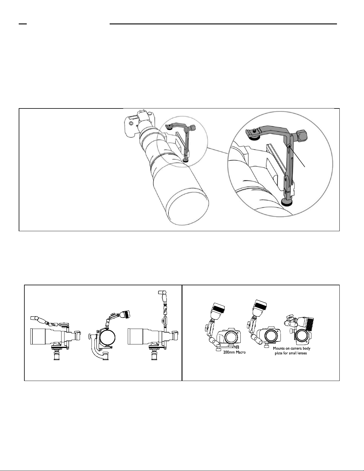
The F-9 is a telephoto bracket that allows you to use an
off-camera flash unit attached to the Wimberley Head Version II
swing arm. This bracket requires the use of an off-camera shoe
cord or wireless adapter recommended by your camera man-
ufacturer (not available through Wimberley).
It is important to read these instructions and to spend some
time getting familiar with the modular parts and how they fit
together. Once you become familiar with the Modules in the
Flash Bracket System, you may well find new and unique
configurations and applications for them.
The standard F-9 Wimberley Head Version II Bracket consists
of two modules: the Tilt Arm (M-3) and the Wimberley Head
Version II Module (M-9). The Modular Flash Bracket System
design allows you to easily disassemble brackets for convenient
storage.
Instructions
F-9
Wimberley Head Version II &
Sidemount Wimberley Flash Bracket
Wimberley, Inc. Phone: 1-434-529-8385
1750 Broadway St Toll Free: 1-888-665-2746 (USA & Canada)
Charlottesville, VA
22902 USA www.tripodhead.com info@tripodhead.com
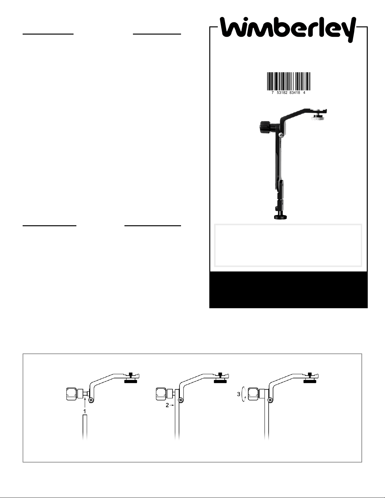
Connecting Flash Bracket Modules:
(The figure below shows the connection between M-9 and M-3;
the same principle applies for other connections.)
1. Unscrew the 5-lobe knob on the M-3 Module until it
reaches the end of its range (exposing about 3/8” of the
threaded stud on which the knob rides). Do not force the knob
past the point of resistance. This knob is captive and should
not come off.
2. Slip the forked end of the M-9 Module over the exposed
threads.
3. Seat the M-9 Module by slipping one of the enlarged
areas in the slot over the cylindrical nub at the base of the
exposed threads on the M-1.
4. Tighten the 5-lobe knob securely.
About the F-9
Dimensions (Overall L x W x H): 5.5” x 1.0” x 8.5”
Weight: 6.5 oz.
Materials: Anodized 6061 Aluminum, stainless steel fasteners
Instructions continued >>
Package Contents:
 M-3 Module: Tilt Arm (Qty 1)
 M-9 Module: Wimberley Head V2 Upright and Quick-
release (Qty 1)
Wimberley, Inc. Phone: 1-434-529-8385
1750 Broadway St Toll Free: 1-888-665-2746 (USA & Canada)
Charlottesville, VA
22902 USA www.tripodhead.com info@tripodhead.com
5 Year Warranty – See www.tripodhead.com/warranty.cfm for complete details
Attaching the F-9 Bracket to the Wimberley Head Version II:
The F-9 bracket is designed to attach to the swing arm of the Wimberley Head Version II™
(WH-200). It is a beneficial telephoto bracket to use with the WH-200 because mounting it
will not affect the balance point of your lens, If you were using the F-1 Telephoto bracket,
you would need to rebalance the lens once the bracket was attached to the lens plate. The
F-9 bracket also stays on the Head when swapping out lenses, which can be very handy in
the field.
NOTE: The F-9 will not fit the swing arm of the vintage Wimberley Heads (WH-100/101)
because the swing arm of the original Wimberley Head is not narrow enough to fit within
the clamping jaw of the M-9 Module (the WH-100 and 101 Head swing arms do not have
machined, Arca-Swiss style grooves to which the bracket can be connected).
The M-9 module has an innovative pivoting, low-profile quick-release clamp, which
eliminates loose screws and the need for tools (Fig. 1). The pivoting jaw allows for
flexibility in positioning of the bracket on the Head.
Instructions (Continued)
The swing arm of the WH-200 has an Arca-Swiss
style, double dovetail along each side of it’s length,
and it is to this that the F-9 bracket attaches.
TIP: It makes it easier to mount the bracket if the
swing arm of the Head is tightened down first.
1. Using the bottom knob on the M-9 quick-release,
open the M-9 module jaws until you meet some
resistance. The knob is captive and should not
come off.
2. Pivot the moving jaw with the knob to either side,
perpendicular to the upright portion of the M-9
module (Fig. 2).
3. Place the bracket above the swing arm. Choose
the configuration that feels best to you
and allows you to comfortably access
the focusing ring on your lens
(Fig. 2, Option 1 & 2).
4. Adjust the width of the clamp jaws so that they
are a just bit wider than the width of the swing
arm grooves. Make sure that the bracket jaws
are completely parallel with the dovetail groove
on the swing arm.
5. Slide the bracket down the swing arm from the
top. Position it above the lens mounting
platform.
6. Once the bracket is in a good position, turn the
M-9 screw knob to tighten the clamp jaws and
secure the bracket on the swing arm.
7. Adjust the bracket height as desired by
loosening the M-9 knob slightly. Re-tighten after
any up or down adjustment is made.
Bottom
Knob
Instructions continued >>
Attaching your Flash Unit:
Wimberley Flash brackets are designed to screw into the 1/4” threaded hole found on the bottom of an off-camera shoe adapter
(usually on one end of a flash cord cable) that connects the camera to the flash. To attach your flash unit, you will need a flash cord
or wireless flash adapter (Fig. 3). The flash cord (or wireless adapter) connects the electrical signal from the hot shoe on your
camera body to the flash unit allowing it to fire properly. We recommend purchasing an adapter that is recommended by your cam-
era manufacturer so it will be compatible with both your flash unit and your camera body. Wimberley does not sell flash cords. We
recommend that you contact your local camera shop for in-depth guidance.
The flash cord has one end that slides into the camera’s flash hot shoe, and another end that slides onto the bottom of the flash
unit. Attach the flash cord to the top of the flash bracket using the silver, captive knurled fastener on the M-3 Tilt Arm. To remove
the flash, be sure to lift up lightly on the flash unit while unscrewing the knurled knob. This will prevent the fastener from
unscrewing from the flash bracket and possibly jamming.
Instructions (Continued)
Figure 4
Flash Cord Compatibility Notes: Nikon Users: the Nikon SC-29 cord requires the use our FA-11 Flash Cord Adapter
(Fig. 4) to attach the cord snugly to the bracket. Canon users: some older Canon off-camera flash cords have a mounting
foot that is slightly too wide to fit properly in the slot on the flash arm. The off-camera adapter has a square footprint. If one of
the sides of the flash adapter square has a lump on it, remove material from the side of the square opposite this lump with a file
until it fits into the groove on the M-3. We apologize for this dimensional incompatibility. We made this design sacrifice so that
the bracket would fit newer Canon cords snuggly.
Figure 3
Canon Off-camera Shoe Cord 3
For wireless set up: the Nikon AS-20 flash unit
stand can be used to mount the Nikon unit to
the Macro Bracket’s round mounting platform.
Nikon SC-29 Off-Camera Shoe
Cord (this cord requires an FA-11
adapter when used with the
following modular brackets: F-1,
F-4, F-6, F-9)
For wireless set up: the Canon
flash unit stand can be used to
mount the Speedlight unit to the
Macro Bracket’s round mounting
platform.
Instructions (Continued)
Other Uses & Add-ons:
1. Add the Wimberley M-4 Macro Arm Module™ by attaching it to, or substituting it for, the M-3 Tilt Arm. This allows you to add
more flash positioning versatility to your telephoto photography (Fig. 6).
2. You can also make a Macro Bracket by removing the M-3 Tilt Arm and adding the M-4 Macro Arm to the M-9 quick-release
module (Fig. 7). Note: the quick-release knob on the M-9 is larger than that of the M-1; this may cause clearance issues in certain configurations.
3. The Wimberley M-6 Extension Post Module™ is a simple post that allows you to extend the height of your flash. The M-
6 Module attaches to the vertical arm of your flash bracket using the same captive fastener system found on several other mod-
ules in the system. The M-6 gives you up to 5” of extension to help you reduce red eye or “steel eye” in your subjects. It can also
help you elevate and extend a flash unit outside a window or blind. If you desire more extension, you can stack extension posts
to get the height you need, and pairs fit together for compact storage.
Positioning your Flash:
The Modular Flash Bracket System design allows you to easily disassemble brackets for convenient storage. It also allows you to
adjust the size of the bracket to fit different sized lenses. The M-3 Tilt Arm module can be adjusted in the keyed slots of the M-9
Module to increase or decrease the height of the flash unit. Adjust the vertical position of the Tilt Arm on the M-9 for telephoto
lenses of different sizes. Flip the Tilt Arm upside down to lower the flash even further (if you do this, you must remove the silver
thumbscrew that holds the flash in place and reinstall it from the opposite side).
You can also attach the Tilt Arm so that it positions the flash off-center. The Tilt Arm is fitted with two stop screws that keep the
flash from tilting forward or backward (Fig. 5). If you wish to tilt the flash forward, simply unscrew the appropriate screw enough to
give you the desired amount of forward rotation. If you are using a collared macro lens, flip the Tilt Arm upside-down. In this
orientation, the stop screws do not engage, and the arm is completely free to tilt forward and backward.
Thank you for your interest in Wimberley products. If you have any questions or comments please feel free to con-
tact us (our contact information is located in the black box on the first page).
Side-mount Configuration:
The F-9 bracket can also be
used on side-mount heads such
as the Wimberley Sidekick.
Swivel the quick-release arm on
the bottom of the bracket to the
straight position and attach the
bracket to the dovetail on your
lens plate.
Figure 5
Stop screw
Figure 7 (M-1 shown, M-9 will work too) Figure 6
Wimberley, Inc. ©2015, All Rights Reserved Rev. 111213

Other Wimberley Camera Accessories manuals

Wimberley P-40 User manual

Wimberley

Wimberley P-40 User manual

Wimberley F-3 User manual

Wimberley

Wimberley F-3 User manual

Wimberley PP-211 User manual

Wimberley

Wimberley PP-211 User manual

Wimberley M-8 User manual

Wimberley

Wimberley M-8 User manual

Wimberley WH-200-S User manual

Wimberley

Wimberley WH-200-S User manual

Wimberley MH-100 User manual

Wimberley

Wimberley MH-100 User manual

Wimberley P-30 User manual

Wimberley

Wimberley P-30 User manual

Popular Camera Accessories manuals by other brands

Really Right Stuff TMC-43C user manual

Really Right Stuff

Really Right Stuff TMC-43C user manual

Darfon B09ULF installation manual

Darfon

Darfon B09ULF installation manual

patura MaxiBox P350 user manual

patura

patura MaxiBox P350 user manual

Ikelite ST1K quick start guide

Ikelite

Ikelite ST1K quick start guide

Leica R9 brochure

Leica

Leica R9 brochure

Induro AKB ADVENTURE operating instructions

Induro

Induro AKB ADVENTURE operating instructions

Meade 884 Deluxe operating instructions

Meade

Meade 884 Deluxe operating instructions

Gitzo Classic Inter Pro Studex Mk2  G1341 G1341 parts list

Gitzo

Gitzo Classic Inter Pro Studex Mk2 G1341 G1341 parts list

Glidecam XR-1000 manual

Glidecam

Glidecam XR-1000 manual

Vello BG-N23 user manual

Vello

Vello BG-N23 user manual

Sanyo UF103450P Specifications

Sanyo

Sanyo UF103450P Specifications

Zhiyun CRANE 2 user guide

Zhiyun

Zhiyun CRANE 2 user guide

PROAIM VI-2AXS-01 Assembly manual

PROAIM

PROAIM VI-2AXS-01 Assembly manual

visual engineering IQS user manual

visual engineering

visual engineering IQS user manual

edelkrone HEADONE user manual

edelkrone

edelkrone HEADONE user manual

Seacam SEAFLASH 150digital user manual

Seacam

Seacam SEAFLASH 150digital user manual

Visceral Psyche Films Leeming LUT Pro Setup guide

Visceral Psyche Films

Visceral Psyche Films Leeming LUT Pro Setup guide

eufy Security SmartTrack Card user manual

eufy Security

eufy Security SmartTrack Card user manual

manuals.online logo
manuals.online logoBrands
  • About & Mission
  • Contact us
  • Privacy Policy
  • Terms and Conditions

Copyright 2025 Manuals.Online. All Rights Reserved.