manuals.online logo
Brands
  1. Home
  2. •
  3. Brands
  4. •
  5. Wimberley
  6. •
  7. Camera Accessories
  8. •
  9. Wimberley F-3 User manual

Wimberley F-3 User manual

Instructions (Continued)
Positioning your Flash:
The Modular Flash Bracket System design allows you to easily disassemble brackets for convenient storage. It also allows you to
adjust the size of the bracket to fit different sized lenses. The M-3 Tilt Arm module can be adjusted in the slots of the M-2 Upright
to increase or decrease the height of the flash unit (Fig. 6). Adjust the vertical position of the Tilt Arm on the Upright for different
telephoto lenses. Flip the Tilt Arm upside down to lower the flash even further (if you do this, you must remove the side
thumbscrew that holds the flash in place and reinstall it from the opposite side).
You can also attach the Tilt Arm so that it positions the flash off-center. The Tilt Arm is fitted with two stop screws that keep the
flash from tilting forward or backward. If you wish to tilt the flash forward simply unscrew the appropriate screw enough to give you
the desired amount of forward rotation. If you are using a collared macro lens, flip the Tilt Arm upside-down (Fig. 6). In this
orientation, the stop screws do not engage and the arm is completely free to tilt forward and backward.
Note: The F-1 bracket offers about 3/4” less height than the largest brackets on the market. This is because it does not need the extra height to
clear the top of the lens barrel (because of the low-profile Tilt Arm). If you find that the F-1 Flash Bracket is not compatible with any of your lenses
in any way, please let us know.
Figure 6 (shown without off-camera flash cord)
Thank you for your interest in Wimberley products. If you have any questions or comments please feel free
to contact us (our contact information is located in the black box on the first page).
Figure 7 Figure 8 Figure 9
Other Uses & Add-ons:
1. If you take out the Upright and attach the Tilt Arm (M-3) directly to the Quick-release Arm (M-1), you have made the F-6 Sidekick
Flash Bracket™, a compact bracket that works with the Wimberley Sidekick and other side-mount tripod heads (Fig. 7).
2. Adding the Macro Arm (M-4) module by either attaching it to, or substituting it for, the M-3 Tilt Arm allows you to add more flash
positioning versatility to your telephoto photography (Fig. 8).
3. If you add the M-4 Macro Arm, and remove both the M-3 and the M-2 Upright, you can make the F-2 Macro Flash Bracket™ (Fig. 9).
4. The Wimberley M-6 Extension Post Module™ is a simple post that allows you to extend the height of your flash. The M-6 module
attaches to the vertical arm of your flash bracket using the same captive fastener system found on several other modules in the system.
The M-6 gives you up to 5” of extension to help you reduce red eye or “steel eye” in your subjects. If you desire more extension, you
can stack extension posts to get the height you need, and pairs fit together for compact storage. See our website or product catalog for
more information on this useful add-on flash module.
Wimberley, Inc. ©2015, All Rights Reserved Rev. 111213
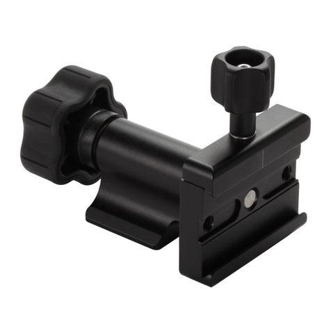
The F-3 Telephoto/Macro Kit™ is a combination of our most
popular flash components of the Wimberley Modular Flash
Bracket System™. The Wimberley Modular Flash Bracket
System brings a new level of versatility and portability to the
world of flash brackets. Included in this kit is the standard F-1
Telephoto Bracket (assembled) and the M-4 Macro Arm
Module.
Wimberley flash brackets attach to most Arca-Swiss style lens
plates and allow you to use an off-camera flash unit. This
bracket requires the use of an off-camera shoe cord or
wireless adapter recommended by your camera manufac-
turer (not available through Wimberley).
It is important to read these instructions and to spend some
time getting familiar with the modular parts and how they fit
together. Once you become familiar with the modules in the
Flash Bracket System, you may well find new and unique
configurations and applications for them.
The F-3 Kit allows you to make the following brackets: the F-1
Telephoto Bracket, the F-6 Sidekick Bracket and F-2 Macro
Bracket. The Modular Flash Bracket System design allows
you to easily change flash height and position, as well as
disassemble bracket components for convenient storage.
Instructions
Wimberley, Inc. Phone: 1-434-529-8385
1750 Broadway St Toll Free: 1-888-665-2746 (USA & Canada)
Charlottesville, VA
22902 USA www.tripodhead.com info@tripodhead.com
Connecting Flash Bracket Modules:
1. Unscrew the 5-lobe knob on one of the components until it
reaches the end of its range, exposing about 3/8” of the
threaded stud on which the knob rides. Do not try to back the
captive knob all the way off. Slip the forked end of the
companion module over the exposed threads (Fig. 1).
2. Seat the companion module by slipping one of the
enlarged areas in its slot over the cylindrical nub at the base of
the exposed threads.
3. Tighten the 5-lobe knob securely.
(The figure below shows the connection between M-2 and M-3;
the same principle applies for other connections.)
About the F-3
Package Contents:
 M-1 Module: Quick-release Arm (Qty 1)
 M-2 Module: Upright (Qty 1)
 M-3 Module: Tilt Arm (Qty 1)
 M-4 Module: Macro Arm (Qty 1)
Dimensions (Overall L x W x H): 5.63 x 1.0 x 9.13 in
Weight: 9.4 oz
Materials: Anodized 6061 Aluminum, stainless steel fasteners
Instructions continued >>
F-3
Telephoto & Macro Flash Bracket Kit
Made in USA
5-lobe knob
cylindrical nub
M-2 companion
module (side view)
M-3 Module
Figure 1
Wimberley, Inc. Phone: 1-434-529-8385
1750 Broadway St Toll Free: 1-888-665-2746 (USA & Canada)
Charlottesville, VA
22902 USA www.tripodhead.com info@tripodhead.com
5 Year Warranty – See www.tripodhead.com/warranty.cfm for complete details
Attaching the Bracket to a Lens:
The F-1 bracket attaches to your lens (or camera) plate using a special narrow, low-profile quick-release clamp, which eliminates
loose screws and the need for tools. The clamp on the bottom (M-1) module can be attached to the bottom of an Arca-Swiss
style plate, or the M-1 can be flipped to attach to the top of the plate if needed (Fig. 2).
Instructions (Continued)
You can attach the F-1 Telephoto bracket to any lens that has an Arca-Swiss style plate mounted to the lens foot. If your current
lens plate is not long enough to accept the flash bracket, Wimberley has a line of quick-release plates that have dovetails milled on
both the upper and lower halves of the plate for increased positioning versatility (Fig. 3).
If you plan to attach the bracket to a lens plate while the lens is attached to a tripod head quick-release clamp, you will need to
make sure you have enough plate length outside the quick-release clamp to accommodate the bracket. The quick-release plates
we recommend for specific lenses in our catalog and on our website provide enough length to allow you to attach a flash bracket to
the plate without sacrificing balance on a gimbal head, or lens safety when the plate is held within a quick-release clamp.
We also make a small, inexpensive adapter plate, the AP-11, which will convert most older, single dovetail plates made by
Really Right Stuff and Kirk to the double dovetail configuration for greater flexibility in bracket attachment. Please see our catalog
or
website for details.
Figure 3
Figure 2
M-3 Module
Tilt Arm
M-2 Module
Upright
M-1 Module
Quick-release Arm
Instructions continued >>
How to work the M-4 Macro Arm: To adjust a ball and clamshell segment, loosen the wing knob of the segment just enough to
allow the ball ends contained in the clamshell to move easily. Do not try to adjust the ball segments before loosening the
clamshell. Also, do not try to back the wing knob all the way off the screw—it is a captive knob. The balls are meant to stay
contained within the clamshell at all times.
Attach your flash to the M-4 module platform end by using an off-camera flash cord adapter recommended by your camera manufacturer.
Most off-camera flash hot shoe adapters will screw onto the 1/4 inch threaded stud on the platform end of the module.
Position the segments as necessary and tighten the wing knobs to hold the segments in place. The screws inside the wing knobs are
stationary and stay stationary as the knob is tightened, therefore a small amount of the screw head will be exposed on the top of the knob
when tightened. When the clamshells are tight, the balls should not slip when the flash unit is mounted on the module.
NOTE: Excessive torque is not required to tighten the clamshells and may cause damage to the module.
Loosen the clamshells after using the module for storage. This will allow the rubber on the balls to expand out to its normal shape and
extend the life of your module.
Instructions (Continued)
You can attach the M-4 macro bracket to the M-1 module of the Wimberley Modular Flash Bracket System to form a
versatile macro flash bracket that works for both collared and non-collared lenses as seen below in Fig. 4.
You can also attach the M-1 Module to the M-3 tilt arm and then attach the M-4 to the tilt arm. This creates another
macro bracket with a little more reach as seen below in Fig. 5. These brackets can be used with the camera in the
vertical or horizontal position and are also good for other applications where you need separation of the flash from
the lens.
Figure 4
Figure 5
Metal
clamshell
Flash / flash cord adapter mounting
platform (1/4-20” stud)
Wing knob on square block (companion
module attachment point)
Aluminum
stem
Hard rubber
“Ram” ball
Aluminum
stem
Wing knob on clamshell segment (captive)

Other Wimberley Camera Accessories manuals

Wimberley M-8 User manual

Wimberley

Wimberley M-8 User manual

Wimberley WH-200-S User manual

Wimberley

Wimberley WH-200-S User manual

Wimberley MH-100 User manual

Wimberley

Wimberley MH-100 User manual

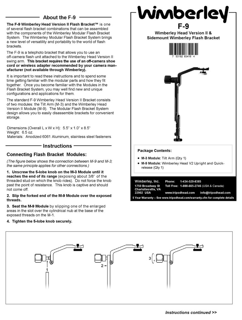
Wimberley F-9 User manual

Wimberley

Wimberley F-9 User manual

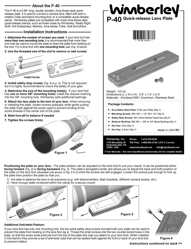
Wimberley P-40 User manual

Wimberley

Wimberley P-40 User manual

Wimberley P-30 User manual

Wimberley

Wimberley P-30 User manual

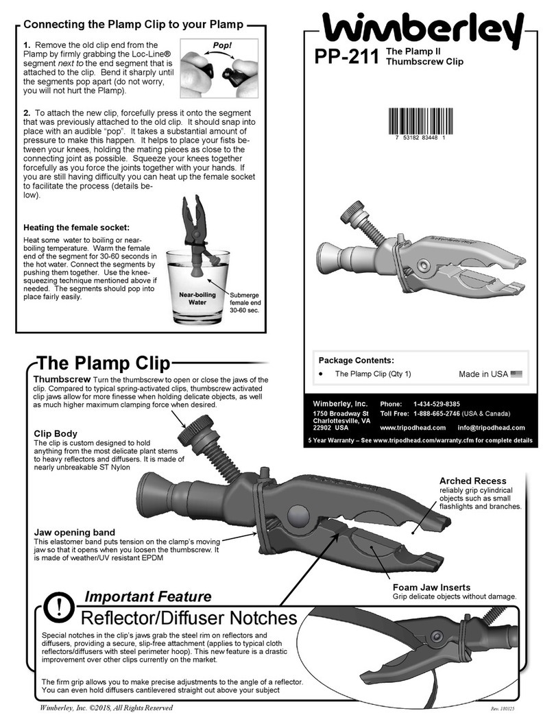
Wimberley PP-211 User manual

Wimberley

Wimberley PP-211 User manual

Popular Camera Accessories manuals by other brands

Intova Sport HD manual

Intova

Intova Sport HD manual

Iconasys 360 Ring Photography Mount Kit Setup guide

Iconasys

Iconasys 360 Ring Photography Mount Kit Setup guide

PROAIM Pro CINEMA Series Assembly manual

PROAIM

PROAIM Pro CINEMA Series Assembly manual

Zeiss T* ZM-Mount Lenses instruction manual

Zeiss

Zeiss T* ZM-Mount Lenses instruction manual

SUNBOUNCE.COM MICRO-MINI operating instructions

SUNBOUNCE.COM

SUNBOUNCE.COM MICRO-MINI operating instructions

Velux KLB 100 instructions

Velux

Velux KLB 100 instructions

PROAIM CINEMA Series Assembly manual

PROAIM

PROAIM CINEMA Series Assembly manual

Panasonic Lumix DMW-MCTZ30 operating instructions

Panasonic

Panasonic Lumix DMW-MCTZ30 operating instructions

Rollei 200 Mark II user guide

Rollei

Rollei 200 Mark II user guide

Davis & Sanford Magnum X3T Specification sheet

Davis & Sanford

Davis & Sanford Magnum X3T Specification sheet

Pylon Technologies RV12100 user manual

Pylon Technologies

Pylon Technologies RV12100 user manual

PROAIM DL-FLDB-01 Assembly manual

PROAIM

PROAIM DL-FLDB-01 Assembly manual

Griots Garage BGB12 user manual

Griots Garage

Griots Garage BGB12 user manual

Axis 25205 manual

Axis

Axis 25205 manual

Sony SPK-TRV1 Service manual

Sony

Sony SPK-TRV1 Service manual

Energizer 371 Product data sheet

Energizer

Energizer 371 Product data sheet

FujiFilm PictureCradle CP-FXA10 operating instructions

FujiFilm

FujiFilm PictureCradle CP-FXA10 operating instructions

Sony PEG-TJ25 CLIE Handbook  (primary manual) installation instructions

Sony

Sony PEG-TJ25 CLIE Handbook (primary manual) installation instructions

manuals.online logo
manuals.online logoBrands
  • About & Mission
  • Contact us
  • Privacy Policy
  • Terms and Conditions

Copyright 2025 Manuals.Online. All Rights Reserved.