WiMo Ultra Beam YAGI 2 User manual

1
MANUAL “STANDARD”
YAGI 2-3-4-6 ELEMENTS 6-20m
Rev. 1.10

2
INTRODUCTION
Ult aBeam p oduced its fi st antenna in 2008.
Since then the e was a p og essive and continuous imp ovement in design and manufactu ing of
antennas, below the main innovations a e listed:
- 2008 dual-d ive ci cuit y to optimize spacing (necessa y on some models)
- 2009 VRS System to imp ove eliability compa ed to sp ing-belt et action systems
- 2010 Engine mounts with di ect connection to the elements fo a complete mechanical seal
- 2016 RCU-06 digital cont olle with colo touch display
Some innovations have become an inte national efe ence, app eciated and used today
successfully even f om othe b ands.
The assembly (p ocessing only pe fo med by the client) is ce tainly one of the most impo tant
aspects of an antenna. The efo e, pa ticula attention has been paid to the technical and
mounting p ocedu es in o de to make the assembly simple, intuitive and fast, even fo
people not much expe ienced in manual labo techniques.
Last but not least, the ealization of elect ical Plug and Play wi ing, as made by Ult aBeam, makes
it ext emely simple to connect the elect ic components p ope ly. Othe wise this pa t would be
sometimes difficult to unde stand and/o often sou ce of post installation p oblems.
The main steps of assembling an Ult aBeam antenna a e in fact common to many models.
Simply by eading this quick guide you will acqui e and memo ize the necessa y p ocedu es in a
few minutes. This makes the assembly of you antenna simple and clea , and, above all, f ee of
any doubts.
The only eal diffe ence between the diffe ent models is the length of the boom and the numbe of
moto units installed on it, but as mentioned above, the p ocedu es and assemble techniques
emains unchanged. The e a e only five steps to successfully install an Ult aBeam antenna and
once the majo p ocedu es a e acqui ed, it will be easy to apply them to you model.
Step Description
1 Boom assembly
2 Mounting b ackets and moto unit on the boom
3 P epa ation of telescope elements
4 Elements Installation on moto unit
5 Elect ic Wi ing
In cont a y to what you might think, this guide will show the simplicity with which you can
achieve both the mechanical and elect ical assembly of an Ult aBeam

3
1) BOOM ASSEMBLY
Ult aBeam uses a squa e boom of section 60 x 60 x 3 mm fo most models of
antennas. Only the heavie models a e equipped with sections of 80 x 80 x 3 mm o 4
mm.
The boom may have 1 to 4 junctions depending on the model.
Only the „2 elements Yagis“ does not have junctions, since they a e const ucted
as a single element. In the following photo sequence, the single juncions a e
shown f om figu e 1 to 5.
Fig.1 Fig.2
Fig.3 Fig.4
Fig.5 Fig.6
NOTE: Befo e tightening the sc ews, make su e that both sides of the L a e in contact with the boom.

4
2) MOUNTING BRACKETS / MOTOR UNIT
The mounting of the engine mounts consists of 3 simple steps
Place the aluminum suppo t on the boom and fix the it by means of the 4 M6 bolts and lowe plates
block (fig.1)
Befo e tightening the bolts, check with a set squa e that the moto suppo t is at 90 ° with espect to
the boom, this will ensu e a pe fect pa allelism between the elements.
Note: In o de to position the moto unit on the boom co ectly you should have a look at the antenna
diag am on page 8. Depending on you model, you need to know that the two exte nal moto units of the
antenna (any model) will always have to be placed at the boom ends, with the cable facing towa ds the
cente of the boom (as shown in the pictu es), so no measu ements needs to be ve ified.
Fig.1 Fig.2 Fig.3
Place the lowe ABS colla s in co espondence of the oute holes of the
suppo t (fig.2)
Inse t the ubbe sleeves on the moto unit and tighten the inte nal clamp
(fig. 3)
Place the moto unit onto the suppo t (Figu e 4) and place the uppe ABS
colla s (fig.5)
Inse t the M6 x 110mm bolts and tighten them.
Figu e A shows the co ect position of the moto unit with espect to the
boom.
Fig.A
Fig.4 Fig.5 Fig.6
Note: To tighten the sc ews, apply to the list below

5
BOLTS TIGHTENING
Passo Description Tightening Nm
M6 Sc ew b acket moto unit
(1)
10
Endless
sc ew
Sc ew ubbe cap clamp (3) 6
M6 Bolt colla s ABS (2) 8
M6 Boom junction sc ew 8
3) PREPARATION OF TELESCOPIC ELEMENT
The glass fibe elements a e fo med by 4 telescopic sections. Its possible to extend eve y single
conical junction to each a total length of about 5.4m maximum extension.
The length can change depending on the model.
The maximum length of each individual section can be diffe ent f om the othe s in o de of
installation. No mally, the inte nal section must emain inside the element that hosts it fo a length
between 8-15 cm (fig.E). Fo this eason the maximum length depends on the set-up and may
diffe in some cm, but this is not a fault and does not matte .
Fig.1 Fig.2 Fig.3
The th ee joints of the element a e sealed by means of the mo-tightening with inte nal adhesive
of app op iate diamete (Figu e 1)
Place the sleeve exactly in the cente of the junction (Figu e 2)
Heat the sleeve with a heat gun until the same has not adhe ed completely to the element, the
leakage of the adhesive to fo m a ing all a ound the edge will indicate that it has eached the
co ect tempe atu e.
NOTE: excessive heat can damage the element

Nota: Specify in the o de if you need optional diamete s. 6
4) INSTALLATION OF ELEMENTS ON MOTOR UNIT
Loosen the outside of the ubbe sleeve so that the element can slide up to whe e it can move, it
will ente 10 cm. (Fig.1)
Tighten the ubbe sleeve clamp (Figu e 2) *
Repeat on opposite side.
Fig.1 Fig.2 Fig.3
MAST/BOOM plate
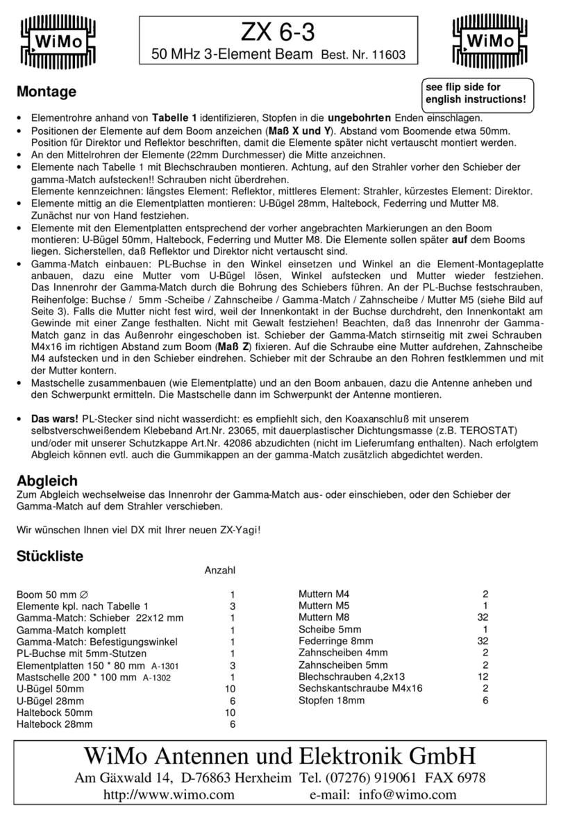
All models a e supplied with aluminium o s/s mast / boom plate.
Mast colla s, boom b ackets and bolts a e made of stainless steel.
Each antenna model will have the app op iate numbe and diamete of colla s to
match the weight of the model.
On all antenna models with th ee moto units, the plates will always be fixed to the
cente boom. Howeve , in cases whe e you need to inc ease the distance between
the cent al element and the mast, simply move the plate away f om the moto
(Fig.3) to achieve the necessa y space fo you set-up. This will be necessa y only
when you install the antenna on a la ge co oos-section wheeled towe .
On antenna models with 4 o mo e elements the position of the plate will be
indicated di ectly on the boom.
In both cases you a e f ee to move f om the specified location and, if necessa y, you can balance the antenna (only fo
epositioning mo e than 10 cm) by placing a small inne weight at the lighte boom end.
Diamete of mast clamps supplied with antennas
U-Bolt Diamete mast mm.
50 60 65
2 elements 6-20 / 6-40 / UB20MX V / /
3 elements 6-20 / UB50 / 4 el. DX V optional /
UB640-VL1.3 / VL2.3 V optional /
4 elements 6-20 V optional optional
3 elements 6-40 / 4 elements 6-40 optional V optional
UB640-VL3.4 / UB40MX optional V optional

7
BOOM Guying
Most Ult aBeam models don‘t need any tie ope, the squa e section boom on models
with a boom length within 6 mete s offe a ve y high stiffness and emain pe fectly
st aight. Only models with boom lengths ove 9 mete s include a guying kit fo the boom.
Models that have boom guying:
UB640-VL3.4
4 ELEMENTS 6-20
4 ELEMENTS 6-40
6 ELEMENTS 6-20 DX
Fig.1
Fig.2
The models shown a e p ovided with a complete kit of excellent Mast Ant opes with suitable diamete fo
the model.
All st ings and joints thimbles a e made of stainless steel.
On the two oute sections of the boom holes a e d illed on which you simply inse t and tighten the th ough
bolt with eyelet head (fig.1) which will be inse ted in the app op iately closed ope with double stainless
junction (fig.2)
The opes a e supplied with p ope length and allow you to make you pe sonal set-up "A"
The ve tical measu ement "A" between boom and mast to which the st ings will be attached to, should
be between 1.5 -2.5 m. The heavie the antenna, the g eate will be the distance f om the antenna
boom. Fo example on a 4 o 6-40 elements it should not be lowe than 2 m.
In any case and ega dless of the model you should neve fix in the cable at distances "A" less than one
mete . This would b ing an excessive load on the opes and poo alignment of the boom.
With the opes kit you get a junction fo mast colla s to tie the opes, of cou se you can use
you own fixtu e if al eady p esent on you mast.
Mast Ant
Redance
Giunzioni co de
A

8
5) ELECTRICAL WIRING
The elect ical wi ing, built and assembled by Ult aBeam, is the best solution fo elect ic connection
between the antenna and the elect onic cont olle .
In these cases, the antenna moto units will be equipped with multi-pole female connecto s.
Simply plug in the connecto s to the moto unit and the DB25 to the cont olle . This avoids any
chance of ope ating e o s and gua antees high eliability ove time.
Fu the mo e, the assembled wi ing does not contain any junction points along the oute, which is often a
cause of bad elect ical contacts especially fo exte nal systems. Each wi e uns f om the cont olle to the
moto . Fo mo e details, see ‘wi ing’ manual on download page of www.ult abeam.de
The multi-wi e cables used in the const uction of the wi ing a e build specifically
acco ding to Ult aBeam specifications.
Wate esistance and p otection against UV ays make the wi ing pa ticula ly suitable
fo outdoo use and offe inc eased eliability compa ed to common comme cial cables.
The connecto s used a e IP68 compliant with gold contacts by Switchc aft Inc.

9
ANTENNA MODEL SCHEME
SCHEMA -Yagi 2 elements 6-20
162 cm
Boom 1 x 162 cm
Sqa e 60 x 60
Boom 3 x 162 cm
Squa e 60 x 60
219 cm

10
D ive 1
D ive 2

11
CONCLUSIONS
A manual of a few pages may seem deceptively simplistic ... actually the use of only 8 pages to desc ibe
the assembly of 2-3-4 elements yagi 6-20 a e p oof of quality design and how ext emely simple as well
as intuitive the assembly of a Ult aBeam antenna eally is.
Texts, images and g aphics have been p epa ed to offe the use maximum ease of self
lea ning and memo izing.
In cont ast to a manual consisting of many pages, which can only confuse an OM having neve
installed an antenna of this type, could p ovide too much info mation and too many new
p ocedu es to him.
Reading new manuals while waiting to eceive you new antenna will allow you to
pe fo m a quick installation, safe and f ee of e o s.
The efo e, a ca eful eading is ecommended in o de to acqui e the assembly methods which, as
you may have seen, a e eally ve y intuitive.
Do wo k when you mind al eady knows what to do and p ovides a bette end esult in fewe
time than a set-up in which you should consult the manual step by step fo each individual
ope ation.
Finally, and not least ...
Pe fo m the antenna set-up exclusively as desc ibed in the manuals.
Avoid any va iable and / o customization.
If you plan to do something that is not desc ibed in the manual, it means you should bette not do it.
D ive
D ive
Position of the cent al
mast plate is indicated.
WiMo Antennen und Elekt onik GmbH
Am Gäxwald 14, D-76863 He xheim Tel. (07276) 96680 FAX 9668-11
http://www.wimo.com e-mail: info@wimo.com
This manual suits for next models
3
Table of contents
Other WiMo Antenna manuals

WiMo
WiMo EAntenna 144XLFA16 User manual

WiMo
WiMo ZX 6-3 User manual

WiMo
WiMo W3DZZ+5 User manual

WiMo
WiMo Kelemen Series User manual
WiMo
WiMo ACOM2000SW User manual

WiMo
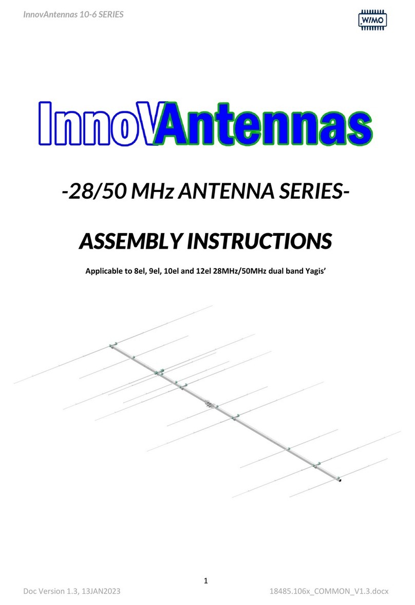
WiMo InnovAntennas 10-6 Series User manual

WiMo
WiMo 18009 User manual

WiMo
WiMo 18007 User manual

WiMo
WiMo CK-868LIN User manual
WiMo
WiMo ULTRABEAM User manual