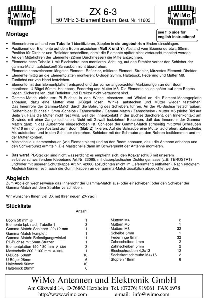
WiMo InnovAntennas 10-6 Series User manual

InnovAntennas 10-6 SERIES
1
Doc Version 1.3, 13JAN2023
18485.106x_COMMON_V1.3.docx
-28/50 MHz ANTENNA SERIES-
ASSEMBLY INSTRUCTIONS
Applicable to 8el, 9el, 10el and 12el 28MHz/50MHz dual band Yagis’

InnovAntennas 10-6 SERIES
2
Doc Version 1.3, 13JAN2023
18485.106x_COMMON_V1.3.docx
CONTENTS
INTRODUCTION ................................................................................................................................................. 3
SPECIFICATIONS................................................................................................................................................. 4
BOOM ASSEMBLY.............................................................................................................................................. 5
ELEMENT ASSEMBLY.......................................................................................................................................... 6
MAST MOUNT ................................................................................................................................................. 13
PACKING LIST................................................................................................................................................... 14
RECOMMENDED ACCESSORIES ....................................................................................................................... 17

InnovAntennas 10-6 SERIES
3
Doc Version 1.3, 13JAN2023
18485.106x_COMMON_V1.3.docx
INTRODUCTION
Thank you for choosing InnovAntennas.
Many dual or multiband Yagis suffer compromising effects as a result of negative interaction between
elements in use and others on the same boom. However, 6m and 10m are two bands where the impact is
small. If sufficient time and attention is taken during the optimisation process, excellent performance in
terms of gain, Front to Back (F/B) and bandwidth too.
Additionally, our 6m/10m range has been optimised for use with a single feedline. This reduces the
requirement for additional coax and connections on the station amplifier or transceiver and ensures
transfer of common mode currents along a secondary feedline back into the shack does NOT occur.
Additionally, both bands can be watched at once on the same radio upon individual VFOs. They single feed
line is therefore ideal for SDR and contest grade radios.
Our Yagis are designed and optimised by computer mechanically as well as electromagnetically and the
same taper scheduling per band (elements) is used throughout our range. Thanks for this superior
mechanical optimisation goes to K7NV (sk) and his exceptional ‘Yagi Stress’ calculator software.
We hope you enjoy the use of your InnovAntennas dual bander for many years to come. It has been
designed to provide many years of trouble-free service.

InnovAntennas 10-6 SERIES
4
Doc Version 1.3, 13JAN2023
18485.106x_COMMON_V1.3.docx
SPECIFICATIONS

InnovAntennas 10-6 SERIES
5
Doc Version 1.3, 13JAN2023
18485.106x_COMMON_V1.3.docx
BOOM ASSEMBLY
Frontally match the boom sections with the same letters (AA, BB, CC, …).
The boom parts with the same cross-sectional sizes are joined by one or multiple boom insert(s) as shown
below:
Boom insert
8 x screw DIN 7380 per joint
16 x washer DIN 9021, M6
1.
2.
8 x Nut selflock DIN 985, M6
Antenna
model
DIN 7380
screw length
10-6 3plus3
50 mm
10-6 4plus4
50 mm
10-6 4plus5
60 mm
10-6 5plus6
60 mm
10-6 6plus7
60 mm

InnovAntennas 10-6 SERIES
6
Doc Version 1.3, 13JAN2023
18485.106x_COMMON_V1.3.docx
ELEMENT ASSEMBLY
The 28MHz and 50MHz elements are mounted to the boom differently from one another. The 28MHz
elements are held in place with plate which support 2 insulator holders for each element (one either side of
the boom) whilst the 50MHz element are held in place by a single insulator bolted directly to the boom.
For the 28MHz mounting plates, there is a single hole in the boom to be married with the central hole in
each element plate. The counter-sunk bolt secures the plate followed by a secondary (smaller) plate on the
reverse side of the boom. The boom is sandwiched between the top plates by means of 4 x M6 bolts.
For the 50MHz elements, just 2 x M6 bolts secure the single element holder in place per boom position.
These bolts pass through the insulator (two halves) that have the 50MHz element centre between them
and are bolted into a pair of threaded boom inserts pre-set in the boom itself.
10 m / 28 MHz ELEMENTS (Reflector REF + Director(s) D1, D2, …)
The element plates (EA01025…) are fixed to their according boom position with a screw DIN7991 M6 x 30
mm through the plate’s central borehole. These element plates will hold the 28 MHz elements
The central parts of the elements are secured on the element plates by the green isolator plastic blocks
EAHYP020 and the according socket head screws, spring washers and self-locking nuts.
The central parts of the elements are easily recognizable due to their slits on both ends, while the extensions only
have slits on one end, the element tips do not have any slits at all.
Screw DIN 7991, M6 x 30

InnovAntennas 10-6 SERIES
7
Doc Version 1.3, 13JAN2023
18485.106x_COMMON_V1.3.docx
Socket head screw DIN 912, M6 x 45
Plastic block Ø 20 mm (EAHYP020)
Screw DIN 7991, M6
Spring washer DIN 127, M6
Nut selflock DIN 985, M6
Element plate
Counter plate EA010085 (models with 50mm boom)
Counter plate EA010083 (models with 40mm boom)
Central 10m element part
Boom size
(cross section)
DIN 7991
screw length
40x40 mm
60 mm
50x50 mm
70 mm
Nut selflock DIN 985, M6
1.
2.

InnovAntennas 10-6 SERIES
8
Doc Version 1.3, 13JAN2023
18485.106x_COMMON_V1.3.docx
10 m / 28 MHz ELEMENTS (driven element DE with feed point)
The active element has central screw terminals and a center insulator. It is secured fourfold to the
element holder as shown below. Otherwise, the mounting material is the same as shown on the
previous page.
6 m / 50 MHz ELEMENTS
These elements consist of a central part (diameter 16 mm) and one extension (diameter 13 mm) on each
side. Use the green plastic blocks (EHAYP016) and screws DIN 912m M6 x 40, to mount the elements to
the boom.
Socket head screw DIN 912, M6 x 40
Plastic block Plastic block Ø 16 mm
(EAHYP016)
Central 6m element part
Screw terminals
Central part of
10m driven element
Element plate
1.
2.

InnovAntennas 10-6 SERIES
9
Doc Version 1.3, 13JAN2023
18485.106x_COMMON_V1.3.docx
Element extensions
All elements are assembled and fixed in length by hose clamps:
Hose Clamp 12 –22 mm
Hose Clamp 10 –16 mm
Hose Clamp 8 –12 mm
Model 10-6 3plus 3
6-Element
Element Diameters
10 m / 28 MHz
Central part: 20 mm
Extension 1: 16 mm
Extension 2: 13 mm
Extension 3: 10 mm
6 m / 50 MHz
Central part: 16 mm
Extension 1: 13 mm
Drawing not to scale
Extension 3
Extension 2
Extension 1
Polycarbonate element spacer + cable ties
to stabilize 10m + 6m driven elements
2x
The drawings on the following pages show the elements
with their extension(s) telescopically mounted for your
antenna model.

InnovAntennas 10-6 SERIES
10
Doc Version 1.3, 13JAN2023
18485.106x_COMMON_V1.3.docx
Model 10-6 4plus4
8-Element
Element Diameters
10 m / 28 MHz
Central part: 20 mm
Extension 1: 16 mm
Extension 2: 13 mm
Extension 3: 10 mm
6 m / 50 MHz
Central part: 16 mm
Extension 1: 13 mm
Drawing not to scale
Extension 3
Extension 2
Extension 1
Polycarbonate element spacer + cable ties
to stabilize 10m + 6m driven elements
2x

InnovAntennas 10-6 SERIES
11
Doc Version 1.3, 13JAN2023
18485.106x_COMMON_V1.3.docx
Model 10-6 4plus5
9-Element
Element Diameters
10 m / 28 MHz
Central part: 20 mm
Extension 1: 16 mm
Extension 2: 13 mm
6 m / 50 MHz
Central part: 16 mm
Extension 1: 13 mm
Drawing not to scale
Extension 2
Extension 1
2x

InnovAntennas 10-6 SERIES
12
Doc Version 1.3, 13JAN2023
18485.106x_COMMON_V1.3.docx
Model 10-6 5plus6
11-Element
Element Diameters
10 m / 28 MHz
Central part: 20 mm
Extension 1: 16 mm
Extension 2: 13 mm
Extension 3: 10 mm
6 m / 50 MHz
Central part: 16 mm
Extension 1: 13 mm
Drawing not to scale
Extension 3
Extension 2
Extension 1
Polycarbonate element spacer + cable ties
to stabilize 10m + 6m driven elements
2x

InnovAntennas 10-6 SERIES
13
Doc Version 1.3, 13JAN2023
18485.106x_COMMON_V1.3.docx
MAST MOUNT
Position of the mast/boom plate on the assembled boom
(measured from the rear end of boom section “A” towards the front)
10-6 3PLUS3
1300 mm
10-6 4PLUS4
1650 mm
10-6 4PLUS5
n/a
10-6 5PLUS6
3000 mm
U-bolt M8
A-0163
Socket head screw DIN 912, M6 x 60 (models with 40x40 mm boom)
Socket head screw DIN 912, M6 x 80 (models with 50x50 mm boom)
Metal bracket 50 mm
23035.50
Mast/boom plate
4 x Washer DIN 127, M8
S127-98
4 x Nut DIN 934, M8
S934-98
Counter plate
EA010085
Washer DIN 127, M6
S127-96
Nut DIN 912, M6
S985-906
1.
2.
The antenna is mounted „upside down”,
meaning that the elements are
BELOW
the boom!
!

InnovAntennas 10-6 SERIES
14
Doc Version 1.3, 13JAN2023
18485.106x_COMMON_V1.3.docx
PACKING LIST

InnovAntennas 10-6 SERIES
15
Doc Version 1.3, 13JAN2023
18485.106x_COMMON_V1.3.docx

InnovAntennas 10-6 SERIES
16
Doc Version 1.3, 13JAN2023
18485.106x_COMMON_V1.3.docx

InnovAntennas 10-6 SERIES
17
Doc Version 1.3, 13JAN2023
18485.106x_COMMON_V1.3.docx
RECOMMENDED ACCESSORIES
InnovAntennas Current Balun (Choke) 1-80 MHz,
3kW
Article No. 18484.0503
InnovAntennas Rubbaseal
Contact Sealant
Article No. 18484.0521
ConductaSeal Aluminium Paste
Article No. 18484.0520
This manual suits for next models
8
Table of contents
Other WiMo Antenna manuals

WiMo
WiMo 18009 User manual

WiMo
WiMo Kelemen Series User manual

WiMo
WiMo EAntenna 144XLFA16 User manual

WiMo
WiMo Ultra Beam YAGI 2 User manual

WiMo
WiMo ACOM2000SW User manual

WiMo
WiMo Bridgepoynt User manual

WiMo
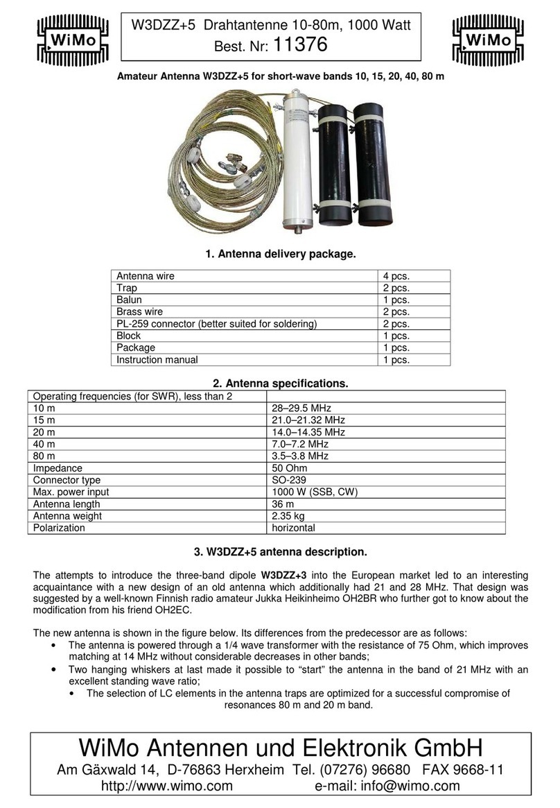
WiMo W3DZZ+5 User manual

WiMo
WiMo ZX 6-3 User manual
WiMo
WiMo CK-868LIN User manual

WiMo
WiMo ULTRABEAM User manual
Popular Antenna manuals by other brands

Renkforce
Renkforce 1391007 operating instructions

Sirius XM RAdio
Sirius XM RAdio NGVA1 installation guide

Rohde & Schwarz
Rohde & Schwarz TSMS-OMN70 installation instructions

Labgear
Labgear LAB480W quick start guide

Plantec
Plantec REEL K60CXW Mounting instructions

DX Engineering
DX Engineering 4-BTV installation instructions