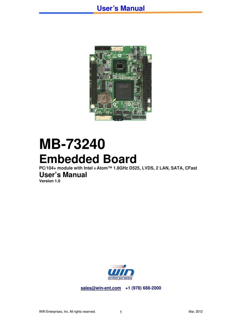
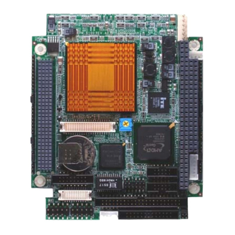
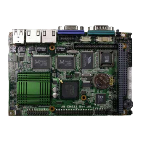
WIN Enterprises MB-73200 User manual

User Manual
Version 1.0B
MB-73200
Intel®Atom™Z5xx Series w/ US15W SCH PC/104+
Module

2
Table of Contents
Chapter 1.General Information………………………………………3
1.1 Introduction……………………………………………………… 3
1.2 Specifications……………………………………………………. 4
1.3 Precautions………………………………………………………. 5
1.4 Board Layout……………………………………………………. 6
1.5 Board Dimensions……………………………………………….. 7
Chapter 2.Connector/Jumper Configuration ……………………….8
2.1 Location of Connectors…………………………………………. 8
2.2 Connector Pin Assignment and Jumper Settings……………. 9
2.3 Location of Jumpers…………………………………………….16
Chapter 3.BIOS Setup………………………………………………18
3.1 Entering the CMOS Setup Program…………………………..18
3.2 Menu Options………………………………………………….. 20
3.3 Advanced Menu…………………………………………………21
3.4 PCIPnP Menu……………………………………………………36
3.5 Boot Menu……………………………………………………….38
3.6 Security Menu……………………………………………………48
3.7 Chipset Menu…………………………………………………….51
3.8 Exit……………………………………………………………… 54
Appendix A: Programming the Watchdog Timer………………… 47
Appendix B: System Resource……………………………………..50
Appendix C: Cable List………………………………………………53

3
Chapter 1. General Information
1.1 Introduction
WIN Enterprises, Inc.,a world-leading technology solution provider in the Industrial PC
(IPC) market and a member of the Intel®Embedded and Communications Alliance,
announces the launch of MB-73200, an ultra low power and compact PC/104+
module product. MB-73200 is built on a highly integrated two-chip solution, the Intel
Atom processor Z5xx series and Intel®System Controller Hub US15W, with total TDP
less than 5 watts.
MB-73200 supports SO-DIMM memory slot for DDR2 SDRAM up to 2GB, and comes
with 2 x SATAconnectors on module. Other I/O functions like 2 COM ports, four USB
2.0 ports, one Parallel port, one Compact Flash socket, 8-bit GPIO, 24bits LVDS and
two 10/100 Ethernet(Intel 82551QM)interface. Besides, MB-73200 supports both
PCI and ISA signals. With only 96 mm x 116 mm board size, PM-7100 is the best
solution for compact, fan-less industrial embedded applications devices.
For more product information, please visit our website www.win-ent.com or contact

4
1.2 Specifications
■
■System
CPU Intel® Atom™ processor Z5xx series Onboard
Z530 SC 1.6GHz FSB 533MHz
Z510 SC 1.1GHz FSB 400MHz
BIOS AMI® 1MB SPI BIOS
System Chipset Intel® System Controller Hub US15W
System Memory 1 x 200-pin socket supports DDR2 533/400* MHz max. up to 2GB
w/o ECC registered
* DDR2 533MHz for Z530 CPU, DDR2 400MHz for Z510 CPU
SSD 50-pin CompactFlash™ type I/II
Watchdog Timer 255 levels timer interval, (1 ~ 255 seconds), setup by software.
Jumper set up for system reset or IRQ
Expansion
Interface PC/104+ for both PCI & ISA signal*
* LPC DMA not supported
Battery Lithium 3V/200mAH
■
■I/O
I/O Chipset Winbond® 83627EHG
I/O Interface 2 x SATA, 1 x CF,
1 x PS/2 KB/Mouse,
1 x RS-232, 1 x RS-232/422/485,
1 x LPT, 1 x IrDA
USB 4 x USB ports, USB 2.0 compliant
Audio (optional) High definition audio interface
(Optional IP-90340 daughter board)
GPIO 8-bit general purpose input/output
■
■Ethernet
Chipset Intel® 82551QM
Speed 10/100Mbps
Interface 2 x RJ-45
Standard IEEE 802.3u (100Base-T) protocol compatible
■
■
Display
Chipset Intel® System Controller Hub US15W
Memory Size Max. up to 256MB sharing system memory
Resolution CRT display mode:
2048 x 1536 x 32bpp (60 Hz);
1920 x 1440 x 32bpp (85Hz);
1600 x 1200 x 32bpp (100Hz)
LCD display mode:
1024 x 768@16bpp (60Hz)
LCD/ LVDS
Interface 18/24-bitTFT LCD
Dual Simultaneous
Display VGA + LCD

5
■
■Mechanical and Environment
Dimensions ( L x W ) 96mm (L) x 116mm (W)
(3.8” L x 4.6” W)
PC/104+ Form Factor
Operating
Temperature 0°C ~ 60°C ( 32°F ~ 140°F )
Operating Humidity 10% ~ 85% relative humidity, non-condensing
Storage
Temperature -20°C ~ 85°C ( -4°F ~ 185°F )
Storage Humidity 5% ~ 95% relative humidity, non-condensing
■
■Power
Power Supply
Voltage AT or ATX power, +5V ±5%, +12V ±5%
Power Consumption 8~12W
■
■
Packing List
z1 x MB-73200
z1 x CD
z1 x Dual RJ45 connectors adaptor card (p/n: IP-90380)
z1 x LAN cable (p/n: CB-ILAN04-00)
z1 x ATX power cable (p/n: CB-IPOW37-00)
z1 x CB- ICOM01-00 (RS-232 cable)
z1 x CB-IVGA04-00 (VGA cable)
z1 x CB-IUSB01-00 (USB cable)
z1 x CB-IPS266-00 (KB/MS cable)
1.3 Precautions
Please make sure you properly ground yourself before handling the MB-73200 board
or other system components. Electrostatic discharge can be easily damage the
MB-73200 board.
Do not remove the anti-static packing until you are ready to install the MB-73200
board.
Ground yourself before removing any system component from it protective anti-static
packaging. To ground yourself, grasp the expansion slot covers or other unpainted
parts of the computer chassis.
Handle the MB-73200 board by its edges and avoid touching its components.

6
1.4 Board Layout
1-5 Board Dimension

7
1.5 Board Dimensions
Component Side, m/m

8
Chapter 2. Connector/Jumper Configuration
Connector Define Connector Define
CN1 VGA connector CN16 USB port 1/2
CN2 LVDS connector CN17 USB port 3/4
CN3 ATX power connector CN18 COM1 RS232
CN4 PS_ON Pin header CN19 COM2 RS422/RS485
CN5 CPLD Pin header (reserved) CN20 Dual SATA connector
CN6 PCI/104 CN21 Power connector
CN7 Power/HDD LED & Speaker CN22 SO-DIMM
CN8 GPI/GPO Pin header CN23 CF socket
CN9 KB/Mouse connector CN24 Battery connector (reserved)
CN10 -5V/-12V power pin header PC/104 PC/104 connector
CN11 LPT connector VR1 LCD VR
CN12 Dual LAN connector
CN13 LCD Inverter connector

9
CN14 COM2 RS232
CN15 HDA connector
2.2 Connector Pin Assignment and Jumper Settings
CN21: Power Connector Pin Assignment
1 +5V
2 +5V
3 Ground
4 Ground
5 +12V
CN3: ATX Power Connector
Pin Assignment
1 5V Standby
2 Ground
3 PS_On
CN4: ATX Power Button
Pin Assignment
1 Power Button +
2 Power Button -

10
CN2: LVDS CONNECTOR
CN9: Keyboard/Mouse Connector Pin Assignment
1 KBCLK#
2 KBDATA#
3 MSCLK#
4 Ground
5 +5V
6 MSDATA#
CN18/CN14: COM1/COM2 RS232 Box Header
Pin Assignment Pin Assignment
1 DCD 2 DSR
3 RXD 4 RTS
5 TXD 6 CTS
7 DTR 8 RI
9 Ground 10 NC
Pin Define Pin Define
1 LVDS0_D0+ 2 LVDS0_D0-
3 GND 4 GND
5 LVDS0_D1+ 6 LVDS0_D1-
7 GND 8 PANEL POWER
9 LVDS0_D2+ 10 LVDS0_D2-
11 LVDS0_CLK+ 12 LVDS0_CLK-
13 GND 14 GND
15 LVDS0_D3+ 16 LVDS0_D3-
17 NC 18 PANEL POWER
19 LCD_SDA 20 LCD_SCL

11
CN1: VGA Connector (Box Header)
Pin Signal Pin Signal
1 RED 2 GREEN
3 BLUE 4 +5V
5 Ground 6 Ground
7 Ground 8 Ground
9 +5V 10 Ground
11 +5V 12 DDC Data
13 H-SYNC 14 V-SYNC
15 DDC Clock 16 NC
CN13: Flat Panel Inverter Connector Pin Assignment
1 +12V
2 Ground
3 FPBKLEN
4 VR
5 +5V
CN12: Dual LAN Connector Pin Signal Pin Signal
1 Lan1-Speed 2 Lan2-Speed
3 Lan1-Act 4 Lan2-Act
5 Lan1-Link 6 Lan2-Link
7 +3.3V 8 Ground
9 Lan-Ground 10 Lan-Ground
11 Lan1-TX+ 12 Lan1-RX+
13 Lan1-TX- 14 Lan1-RX-
15 Ground 16 Ground
17 Lan2-TX+ 18 Lan2-RX+
19 Lan2-TX- 20 Lan2-RX-
CN16/CN17: USB1&2/USB3&4 Connector (Pin Header)
Pin Assignment Pin Assignment
1 +5V 2 +5V
3 Data0- 4 Data1-
5 Data0+ 6 Data1+
7 Ground 8 Ground
9 Key Pin 10 Ground

12
CN11: Parallel Port Connector Pin Assignment Pin Assignment
1 STRPBE 14 AUTOFD
2 PD0 15 ERR
3 PD1 16 INIT
4 PD2 17 SLCTIN
5 PD3 18 Ground
6 PD4 19 Ground
7 PD5 20 Ground
8 PD6 21 Ground
9 PD7 22 Ground
10 ACK# 23 Ground
11 BUSY 24 Ground
12 PE 25 Ground
13 SLCT 26 Ground
CN19: COM2 –RS422/RS485 Connector(Pin Header) Pin Assignment
1 485RXD-
2 485RXD+
3 485TXD+
4 485TXD-

13
CN6: PC/104 Plus Connector
Signal Pin Signal Pin Signal Pin Signal Pin
Ground A1 NC B1 +5V C1 AD00 D1
VIO A2 AD02 B2 AD01 C2 +5V D2
AD05 A3 Ground B3 AD04 C3 AD03 D3
C/BE0# A4 AD07 B4 Ground C4 AD06 D4
Ground A5 AD09 B5 AD08 C5 Ground D5
AD11 A6 VIO B6 AD10 C6 M66EN D6
AD14 A7 AD13 B7 Ground C7 AD12 D7
+3.3V A8 C/BE1# B8 AD15 C8 +3.3V D8
SERR# A9 Ground B9 SBO# C9 PAR D9
Ground A10 PERR# B10 +3.3V C10 SDONE D10
STOP# A11 +3.3V B11 LOCK# C11 Ground D11
+3.3V A12 TRDY# B12 Ground C12 DEVSEL# D12
FRAME# A13 Ground B13 IRDY# C13 +3.3V D13
Ground A14 AD16 B14 +3.3V C14 C/BE2# D14
AD18 A15 +3.3V B15 AD17 C15 Ground D15
AD21 A16 AD20 B16 Ground C16 AD19 D16
+3.3V A17 AD23 B17 AD22 C17 +3.3V D17
IDSEL0 A18 Ground B18 IDSEL1 C18 IDSEL2 D18
AD24 A19 C/BE3# B19 VIO C19 IDSEL3 D19
Ground A20 AD26 B20 AD25 C20 Ground D20
AD29 A21 +5V B21 AD28 C21 AD27 D21
+5V A22 AD30 B22 Ground C22 AD31 D22
REQ0# A23 Ground B23 REQ1# C23 VIO D23
Ground A24 REQ2# B24 +5V C24 GNT0# D24
GNT1# A25 VIO B25 GNT2# C25 Ground D25
+5V A26 CLK0 B26 Ground C26 CLK1 D26
CLK2 A27 +5V B27 CLK3 C27 Ground D27
Ground A28 INTD# B28 +5V C28 RST# D28
+12V A29 INTA# B29 INTB# C29 INTC# D29
-12V A30 NC B30 NC C30 Ground D30

14
PC/104 Connector:
It is a standard PC/104 bus connector, and it is fully occupied with the signals of the
“ISA” (PC/AT) bus. It offers full architecture, hardware and software compatibility
with the ISA bus and can accept ultra-compact (3.6” x 3.8”) stackable modules.
Signal Pin Signal Pin Signal Pin Signal Pin
Ground C0 Ground D0 IOCHCHK A1 Ground B1
SBHE* C1 MEMCS16* D1 SD7 A2 RESET B2
LA23 C2 IOSC16* D2 SD6 A3 +5V B3
LA22 C3 IRQ10 D3 SD5 A4 IRQ9 B4
LA21 C4 IRQ11 D4 SD4 A5 -5V B5
LA20 C5 IRQ12 D5 SD3 A6 NC B6
LA19 C6 IRQ15 D6 SD2 A7 -12V B7
LA18 C7 IRQ14 D7 SD1 A8 0 wait state B8
LA17 C8 NC D8 SD0 A9 +12V B9
MEMR* C9 NC D9 IOCHRDY A10 NC B10
MEMW* C10 NC D10 AEN A11 SMEMW# B11
SD8 C11 NC D11 SA19 A12 SMEMR* B12
SD9 C12 NC D12 SA18 A13 IOW* B13
SD10 C13 NC D13 SA17 A14 IOR* B14
SD11 C14 NC D14 SA16 A15 NC B15
SD12 C15 NC D15 SA15 A16 NC B16
SD13 C16 +5V D16 SA14 A17 NC B17
SD14 C17 MASTER* D17 SA13 A18 NC B18
SD15 C18 Ground D18 SA12 A19 REFRESH* B19
NC C19 Ground D19 SA11 A20 SYSCLK B20
SA10 A21 IRQ7 B21
SA9 A22 IRQ6 B22
SA8 A23 IRQ5 B23
SA7 A24 IRQ4 B24
SA6 A25 IRQ3 B25
SA5 A26 NC B26
SA4 A27 TC B27
SA3 A28 BALE B28
SA2 A29 +5V B29
SA1 A30 OSC B30
SA0 A31 Ground B31
Ground A32 Ground B32

15
CF Socket:
CompactFlash™ is a very small removable mass storage device; it provides complete
PCMCIA-ATA functionality and compatibility pluse TrueIDE functionality compatible
with ATA/ATAPI-4.
CompactFlash storage products are solid state, meaning they contain no moving parts,
and provide users with much greater protection of their data than conventional
magnetic disk device.
Pin Assignment Pin Assignment Pin Assignment Pin Assignment Pin Assignment
1 Ground 11 Ground 21 D00 31 D15 41 RESET
2 D03 12 Ground 22 D01 32 CS 42 ORDY
3 D04 13 VCC 23 D02 33 NC 43 NC
4 D05 14 Ground 24 WP 34 IOR 44 REG
5 D06 15 Ground 25 NC 35 IOW 45 LED
6 D07 16 Ground 26 NC 36 WE 46 BVD
7 CS 17 Ground 27 D11 37 RDY/BSY 47 D08
8 Ground 18 A02 28 D12 38 VCC 48 D09
9 Ground 19 A01 29 D13 39 SCSE; 49 D10
10 Ground 20 A00 30 D14 40 NC 50 Ground

16
2.3 Location of Jumpers
Connector Define
JP1 LVDS VCC Select
JP3 CMOS Clear
JP4 WatchDog Timer Mode Select
JP5 CF Master/Slave Mode Select
JP6 PCI VIO Select
JP7 COM2 RS232/422/485 Select
JP8 COM1 RI/Voltage Select

17
JP1: LVDS VCC Select.
1-2 : +3.3V (Default)
2-3 : +5V
JP3: CMOS Clear
1-2 : Hold CMOS(Default)
2-3 : Clear CMOS
JP4: WatchDog Timer Mode Select
1-2 : IRQ11
2-3 : Reset(Default)
JP5: CF Master/Slave Mode Select
1-2 : Master(Default)
Open: Slave
JP6: PCI VIO Select
1-2 : +3.3V(Default)
2-3 : +5V
JP7: COM2 RS232/422/485 Select
1-2 : RS232(Default)
3-4 : RS422
5-6 : RS485
JP8: COM1 RI/Voltage Select
1-2 : Ring(Default)
2-3 : +5V
3-4 : +5V
4-5 : +12V
JP9: COM2 RI/Voltage Select
1-2 : Ring(Default)
2-3 : +5V
3-4 : +5V
4-5 : +12V

18
Chapter 3. BIOS Setup
3.1 Entering the CMOS Setup Program
Use the CMOS Setup program to modify the system parameters to reflect the options
installed in your system and to customize your system. For example, you should run
the Setup program after you:
1. Received an error code at startup
2. Install another disk drive
3. Use your system after not having used it for a long time
4. Find the original setup missing
5. Replace the battery
6. Change to a different type of CPU
7. Run the Flash program to update the system BIOS
Run the CMOS Setup program after you turn on the system. On-screen
instructions explain how to use the program.
Enter the CMOS Setup program’s main menu as follows:
1. Turn on or reboot the system.After the BIOS performs a series of diagnostic
checks, the following message appears:
“Press DEL to enter SETUP”
2. Press the <DEL> key to enter CMOS Setup program. The main menu
appears:

19
3. Choose a setup option with the arrow keys and press <Enter>. See the
following sections for a brief description of each setup option.
AMIBIOS: Displays the auto-detected BIOS information.
Processor: Displays the auto-detected CPU specification.
System Memory: Displays the auto-detected system memory.
SystemTime: [hour:min:sec]
This item allows you to set the system time.
System Date: [Day mm/dd/yyyy]
This item allows you to set the system date.
In the main menu, press F10 (“Save Changes and Exit”) to save your changes
and reboot the system. Choosing “Discard Changes and Exit” ignores your
changes and exits the program. Pressing <ESC> anywhere in the program
returns you to the main menu.

20
3.2 Menu Options
The main menu options of the CMOS Setup program are described in the following
and the following sections of this chapter.
Main: For changing the basic system configurations.
Advanced: For changing the advanced system settings.
PCIPnP: For changing the advanced PCI/PnP Settings.
Boot: For changing the system boot configurations.
Security: Use this menu to set User and Supervisor Passwords.
Chipset: For changing the chipset settings.
Exit: For selecting the exit options and loading default settings.
Table of contents
Other WIN Enterprises Control Unit manuals
Popular Control Unit manuals by other brands

Yoshitake
Yoshitake AF-10EN product manual

Hewlett Packard Enterprise
Hewlett Packard Enterprise FM 3180 installation guide

Emerson
Emerson KEYSTONE OPTISEAL F16 Installation and maintenance instructions

Wurth Elektronik
Wurth Elektronik Telesto-II user manual

BWS
BWS PROFESSIONAL II Series Operation manual

Gude
Gude GAA 1000 Translation of the original instructions